

Page 1
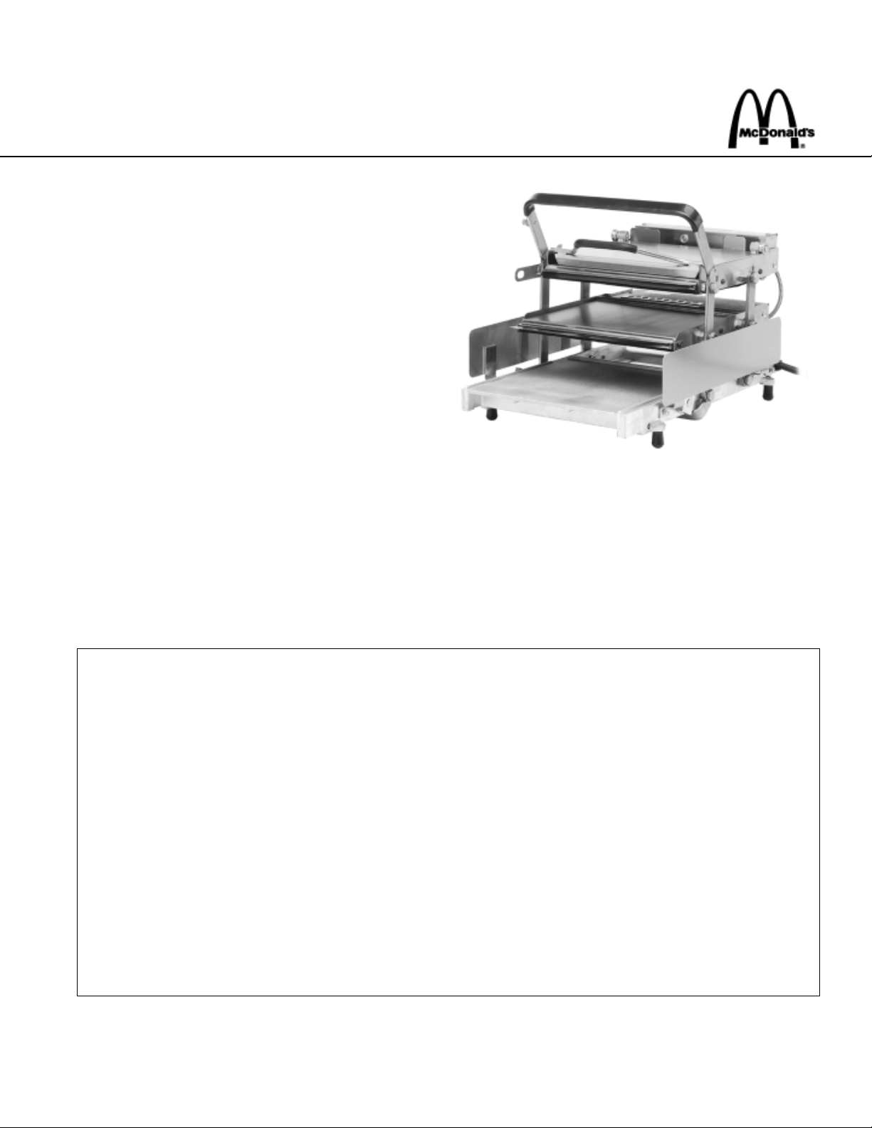
SOLID STATE DIGITAL ENERGY SAVING TOASTER
PRINCE CASTLE MODEL NO. 411-D SERIES
This equipment chapter is to be placed in the
toasters section of your Equipment Manual.
MANUFACTURED FOR
MCDONALD’S®
BY
PRINCE CASTLE INC.
355 KEHOE BLVD.
CAROL STREAM, IL. 60188 USA
PHONE 1-630-462-8800
TOLL FREE NUMBER
1-800-323-2930
FAX:1-630-462-1460
WARRANTY ................................................................................................................................................................................................ Page 1
SIDE VIEW .................................................................................................................................................................................................. Page 2
FRONT VIEW .............................................................................................................................................................................................. Page 3
REAR VIEW................................................................................................................................................................................................. Page 3
INTERNAL VIEW ........................................................................................................................................................................................ Page 4
EQUIPMENT SET-UP ................................................................................................................................................................................ Page 5
PROGRAMMING ........................................................................................................................................................................................ Page 6
CLEANING .................................................................................................................................................................................................. Page 8
TROUBLESHOOTING ................................................................................................................................................................................ Page 8
DI AGNOSTIC TROUBLESHOOTING .......................................................................................................................................................... Page 9-10
TRANSLATIONS (FRENCH, GERMAN, SPANISH, ITALIAN) ........................................................................................................... Page 11-34
WIRING DIAGRAM .................................................................................................................................................................................... Page 35
LIMITED WARRANTY
This product is warranted to be free from defects in material and/or workmanship for a period of (2) years
from date of original installation not to exceed 30 months from date of shipment from our factory. Printed
circuit boards and platen are warranted for a period of (3) years from date of original installation not to
exceed 42 months from date of shipment from our factory. Any part or component which proves to be
faulty in material and/or workmanship within the warranty period will be replaced or repaired without cost to
the customer for parts or labor. (At the option of Prince Castle, Inc.)
This warranty is subject to the following exceptions/conditions:
Any use of Non-genuine Prince Castle spare parts voids this warranty, and all work must be performed
by an authorized Prince Castle Service Agent.
All labor should be performed during regular working hours. Overtime premium will not be covered.
Travel charges are limited to 100 miles (200 km) round trip, 2 hours travel time, one trip per repair.
Damage caused by carelessness, neglect, and/or abuse (e.g., using wrong current, dropping , tamper-
ing with or altering electrical components, or improper cleaning) is not covered.
Equipment damaged in shipment, by fire, flood or an act of God.
This manual is for the exclusive use of licensees and employees of McDonald’s Systems, Inc.
Printed in October
Part No. 411-545
2000 McDonald’s Corparation Printed in the
All Rights Reserved United States of America
Page 2
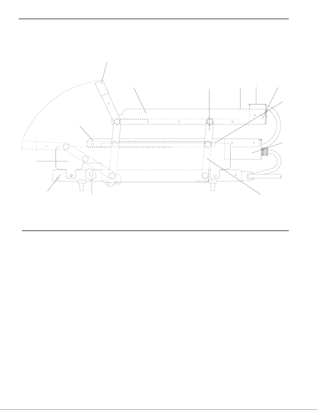
SIDE VIEW
1
12
11
13
10
2
3456
7
8
9
PARTS LIST
ITEM PART NUMBER DESCRIPTION
1 411-149S Handle and Lever Assy.
2 411-441 Right Hand Upper Bun Fence
411-440 Left Hand Upper Bun Fence
3 411-461S Upper Rear Lever Assy.
4 411-378 Upper Rear Bun Fence
5 411-31 Upper Cover
6 411-283 Upper Chassis
7 411-381 Lower Rear Bun Fence
8 411-741 Lower Chassis
9 411-459S Lower Rear Lever Assy.
10 411-137 Right Hand Stop Block
411-138 Left Hand Stop Block
11 411-2S Base
12 411-444 Side Panel, Right Hand
411-445 Side Panel, Left Hand
13 411-379 Right Hand Lower Bun Fence
411-380 Left Hand Lower Bun Fence
Not Shown 411-114 Safety Latch
Not Shown 411-744 Bun Board
2
Page 3
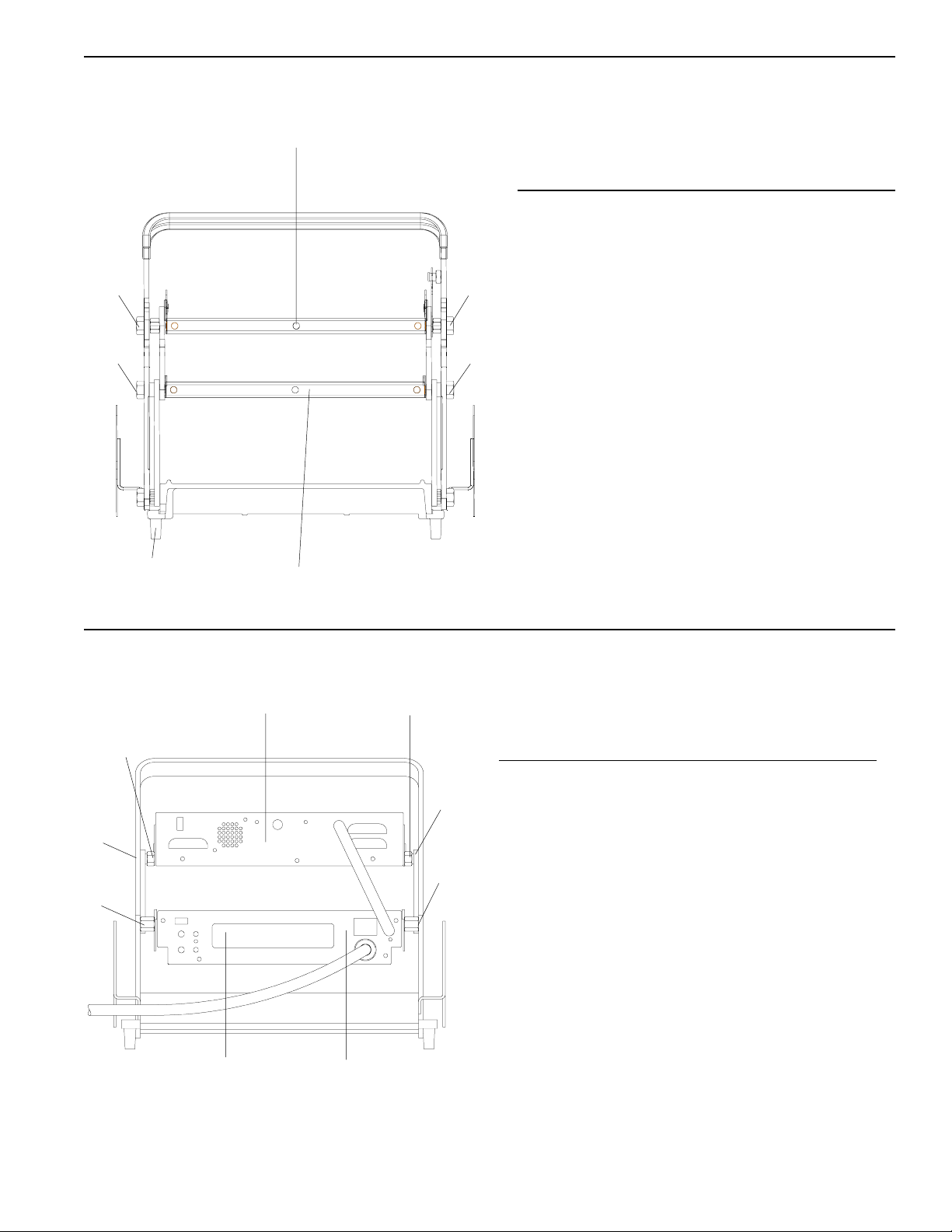
FRONT VIEW
1
PARTS LIST
2
3
5
REAR VIEW
2
3
4
1
2
ITEM PART NUMBER DESCRIPTION
1 411-483S Upper Platen 230V
411-6S Upper Platen 120V
2 411-60 Front Upper
Platen Stud
3 411-60 Front Lower
Platen Stud
4 411-486S Lower Platen 230V
411-8S Lower Platem 120V
5 89-959S Foot (Pkg. of 4)
2
PARTS LIST
3
3
4
4
6
5
ITEM PART NUMBER DESCRIPTION
1 411-712 Upper Faceplate
2 411-57 Platen Spacer
3 411-147 Rear Upper
Platen Stud
4 411-61 Rear Lower
Platen Stud
5 411-705 Lower Faceplate
6 411-707 Overlay
3
Page 4
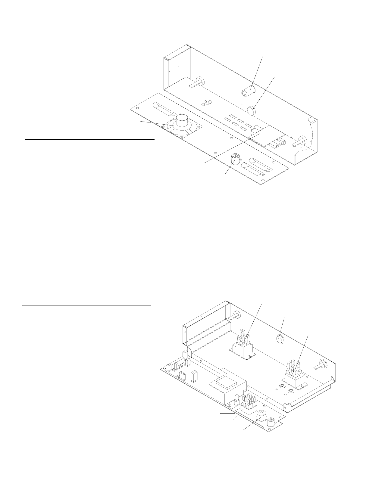
INTERNAL VIEW UPPER CONTROL BOX
5
PARTS LIST
1
2
ITEM PART NUMBER DESCRIPTION
1 213-257S Bun Done Light
2 411-700S Upper Probe
3 411-740 Interconnect Cable
4 411-14S Interconnect Board
5 213-229S Speaker
INTERNAL VIEW LOWER CONTROL BOX
PARTS LIST
ITEM PART NUMBER DESCRIPTION
4
3
1
2
1
1 65-053-04S Relay, Lower & Upper
2 411-700S Probe
3 72-301S Power Cord 220-230V
72-274 Power Cord 120V
4 78-166S Rocker Switch
5 411-427-05S Control PCB 220-230V
411-601S Control PCB 120V
5
4
3
4
Page 5

SYMBOLS & TERMS
C - - A Toaster is set on Celsius.
F - - A Toaster is set on Fahrenheit.
A L - Alarm Level setting 1-4.
for Celsius, and the “A” will begin to count down 9
seconds. During this countdown, you can change
the temperature display from Celsius to Farenheit
readings. To change temperature display, press
and hold the temperature button for six seconds.
See figure 1.
Sound Button: Used with timer button
and temperature button to set alarm level.
Timer Button: Used to view time in run
mode. Used to set time in program
mode.
Temperature Button: Used to view set
point temperature in run mode, and used
to set the set point temperature in program mode.
Up Arrow: Used to set time, sound and
temperature in program mode.
Down Arrow: Used to set time, sound,
and temperature in program mode.
ENERGY SAVING MODE
To conserve energy during non-toasting periods, pull
the toaster handle down, so that the timing cycle
activates. When the audio alarm goes off, indicating
that the toasting time is complete, DO NOT pull the
handle up. Allow the audio alarm to sound until the
alarm shuts off, the display will alternatly flash
“Stand” and “By”,indicating the toaster is in the
energy savings mode. The toaster platens will
continue to maintain the programmed operating
temperature, raising the toaster handle will put the
toaster back into the operation mode.
figure 1
F - -
3. During the pre-heat cycle, the display will read L O -. When the platen temperature reaches
149° C (300° F), the display will begin to show
the actual platen temperatures throughout the
toasting cycles. See figure 2
figure 2
- L O -
1 4 9
FACTORY PRE-SET
Prince Castle’s Solid State Digital Display toasters are
pre-set at the factory.
If your toaster model is set for a 35 second toast time,
then the temperature is pre-set and calibrated to 215°C.
If your toaster model is set for a 55 second toast time,
then the temperature is pre-set and calibrated to 204°C.
SET-UP
1. Refer to the nameplate on the control box for the
proper operating voltage. Connect the toaster to a
grounded receptacle that matches the nameplate
voltage information. Press the power switch to the
on position, allow the unit 30 minutes to reach
operating temperature.
2. The toaster is factory-set to display temperatures
reading in Celsius. When the toaster is turned on,
the digital display on the controll box will read C--A
5
Sound Level Adjustment
The audio alarm has four sound levels.
1.Press and hold the time button and temperature
buttons simultaneously. The display will show the
current sound level. The toasters are factory set at
level 4, and the display will read, A L 4 for Alarm
Level 4. See figure 3.
figure 3
A L 4
Page 6

2. While holding the time and temperature buttons,
press the up or down arrow buttons to adjust the
sound level. A continuous tone will sound.
Release all buttons when the desired sound level
is reached. The display will show the current
sound level. See figure 4.
figure 4
A L 2
figure 6
SET TIME
2 0
PROGRAMMING
The programming modes are used for setting individual
set point temperature, and setting toast times.
Programming the Set Point Temperature
VIEW SET POINT TEMPERATURE
1. Press and release the temperature button. (Do not
hold for more than 6 seconds.) A beep will sound,
the temperature indicator will turn on, and the
display will show the set point temperature for three
seconds. The display will then change to show the
actual temperature. See figure 5.
figure 5
SET POINT TEMPERATURE
2 1 5
ACTUAL TEMPERATURE
1. Press and hold the temperature button for six
seconds. A beep will sound, the temperature
indicator light will blink, and the display will show
the current set point temperature. See figure 7.
figure 7
215
2. To change the set point temperature, use the up
or down arrow. Once the desired temperature is
displayed, press the temperature button to store
the new setting. See figure 8.
figure 8
ADJUST SET POINT TEMPERATURE
2 1 6
VIEW TIMER SETTING
1. Press and release the time button. (Do not
press the time button for more than 6 seconds.)
The set time will be displayed for three seconds.
If the timer is activated and is in a countdown
sequence, the time remaining will be displayed,
and will continue to countdown to zero. After
three seconds, the display will change to show
actual platen temperature. See figure 6.
2 0 4
STORE SET POINT TEMPERATURE
2 0 4
6
Page 7

3. To cancel the set point programming mode at any
time, press and release the time button. The
display will change to show the actual platen
temperature. See figure 9.
figure 9
3. To cancel the time set function at any time, press and
release the temperature button. The time indicator
light will turn off, and the display will change to show
the actual platen temperature. See figure 12.
figure 12
2 1 5
Programming Toast Times
1. Press and hold the time button for 6 seconds. A
beep will sound, and the time indicator light will
blink. Release the time button to show the
current toast time. See figure 10.
figure 10
5 5
2. Use the up and down arrow buttons to set your
desired toast time. The range is from 20 seconds
to 1 minute, 30 seconds. When desired time is
reached, press and release the time button to
store the new time. See figure 11.
figure 11
2 1 5
SETTING STOP BLOCKS
Stop blocks allow for proper crush when toasting
buns. The toaster leaves the factory with the stop
blocks set on R/Q.
Dual stop blocks allow you to switch back and forth
from Reg/Qtr. bun and Big Mac Bun toasting, or Rib
bun or Rye bun toating.
1. Ensure the stop blocks are on the correct setting.
There are (6) combination Stop Block Settings:
1. R/Q / MAC 4. RIB / RYE
2. R/Q+ / MAC + 5. RIB+ / RYE +
3. R/Q- / MAC - 6. RIB- / RYE -
THE (+) SETTING IS FOR BUNS THAT ARE CUT
TOO THICK. THE (-) SETTING IS FOR BUNS CUT
TOO THIN. FOR NORMAL SIZE BUNS DO NOT USE
(+) or (-) SETTINGS.
[R/Q = REG/QTR]
SETTING THE NEW TIME
3 5
STORING THE NEW TIME
3 5
2. Rotate stop blocks by hand to the desired
combination bun setting listed above.
3. View the stop block setting selected through the
index window bracket, which is located over the
left stop block. See figure 13.
figure 13
SIDE PANEL
INDEX WINDOW BRACKET
STOP BLOCK
BUN SETTING
(REGULAR BUNS)
7
Page 8

4. To switch between the two types of buns per
your stop block setting, locate the selector lever
on the front of the toaster frame. Move the lever
left or right to switch back and forth between the
combination setting. See figure 14.
figure 14
FRONT OF
FRAME
figure 15
CLEANING
SELECTOR
LEVER
BUN BOARD ADJUSTMENTS
1. Push or pull the bun board handle to desired
notched setting as indicated by graphics
stamped on top of bun board. See figure 15.
2. Bun board graphics are:
FRONT = REG, RYE, QTR HEELS
REAR = BIG MAC, (CROWNS) AND RIB HEELS
1. Press the power switch to the off position.
2. Unplug toaster.
3. Allow toaster and platens to cool down.
4. Wipe entire platen with clean, damp grill cloth.
Full toaster cleaning must be done in the morning when toaster is cold. See your Planned
Maintenance Card for proper cleaning procedures.
IMPORTANT: Do not drape cord over hot toaster bun
board or platen. This will cause cord to burn.
TROUBLESHOOTING GUIDE
PROBLEM CAUSE SOLUTION
Platen loose. Platen bolts loose. Tighten platen bolts.
Buns being crushed. Stop blocks not adjusted Adjust stop blocks.
properly.
Warped bun trays. Straighten or replace bun
trays.
Buns cut improperly. Contact bakery.
No Display. Fuse Defective. Check fuse with ohmmeter,
reading should be 1-2 ohms.
DIAGNOSTIC SIGNALS
This toaster comes with self-diagnostic signals. When the P.C. Board senses a component
failure, the display will change from showing the actual temperature to one of the signals listed on
the following two pages, an audio alarm will sound when an error code message is displayed.
There are two different error code alarms. During a “LO” temp signal, the alarm will alternately
beep 5 times then pause for 5 seconds until the platen heats back up to the toasting temperature.
All other error code messages will be accompanied by an alarm that alternately sounds for 6
seconds then goes silent for 2 minutes.
8
Page 9

Diagnostics Problem Solution
Stand
Lo
EO1
E1O
EO2
E2O
EO3
E3O
Display alternately flashes “Stand” and
“bY” Toaster in Energy Saving Mode
Raise handle to begin toasting. If
display doesn’t change, replace
timer switch.
Platen temperature dropped 54°F
(12°C) below set point temperature.
Stop toasting for 5-10 minutes to
allow toaster to reach set point
temperature
1. Lower Relay Contacts Shorted. Replace Lower Relay.
Lower Platen Overheating.
1. Upper Relay Contacts Shorted. Replace Upper Relay.
Upper Platen Overheating.
2. Lower Probe Open. Replace Lower Probe.
2. Upper Probe Open Replace Upper Probe.
3. Lower Failures E01 And E02 Replace Lower Relay & Probe
3. Upper Failures E10 And E20 or Replace Upper Relay & Probe or
Interconnect board failure. Replace Interconnect Board
EO4
4. Lower Platen Underheating. Replace Lower Relay.
Check Lower Platen Resistance.
E4O
4. Upper Platen Underheating. Replace Upper Relay
Check Upper Platen Resistance.
E44
4. Both Platens Underheating. Replace Both Relays.
Check resistance on platens.
NOTE: E04, E40 and E44 codes indicate the platen temperatures have dropped 90° F or 30°C below the set
point temperature and can be caused by the following: 1. Cool air blowing on the platens
2. Low voltage applied to toaster.
3. Continued toasting during “LO” temp periods.
4. Defective P.C. Board.
EO5
E5O
EO6
5. Lower Failures E01 And E04 Replace Lower Relay
5. Upper Failures E10 And E40 Replace Upper Relay
6. Lower Failures E02 And E04 Replace Lower Relay & Probe
E6O
6. Upper Failures E20 And E40 Replace Upper Relay & Probe
9
Page 10

EO7
7. Lower Failures E01, E02 And E04 Replace Lower Relay & Probe
E7O
EO8
E8O
EO9
E9O
EOA
EAO
7. Upper Failures E10, E20 And E40 Replace Upper Relay & Probe
8. Lower Probe Circuit Failure. Replace P. C. Board.
8. Upper Probe Circuit Failure. Replace P. C. Board.
9. Lower Failures E01 And E08 Replace Lower Relay & PC Board
9. Upper Failures E10 And E80 Replace Upper Relay & PC Board
10.Lower Failures E02 And E08 Replace Lower Probe & PC Board
10.Upper Failures E20 And E80 Replace Upper Probe & PC Board
EOB
EBO
EOC
ECO
EOd
EdO
EOE
EEO
11.Lower Failures E01, E02 And E08 Replace Lower Relay, Probe &
PC Board
11.Upper Failures E10, E20 And E80 Replace Upper Relay, Probe &
PC Board.
12.Lower Failures E04 And E08 Replace Lower Relay & PC Board
12.Upper Failures E40 And E80 Replace Upper Relay & PC Board
13.Lower Failures E01, E04 And E08 Replace Lower Relay & PC Board
13.Upper Failures E10, E40 And E80 Replace Upper Relay & PC Board
14.Lower Failures E02, E04 And E08 Replace Lower Probe, Relay &
PC Board
14.Upper Failures E20, E40 And E80 Replace Upper Probe, Relay &
PC Board.
10
Page 11

WIRING DIAGRAM
35
 Loading...