

Page 1
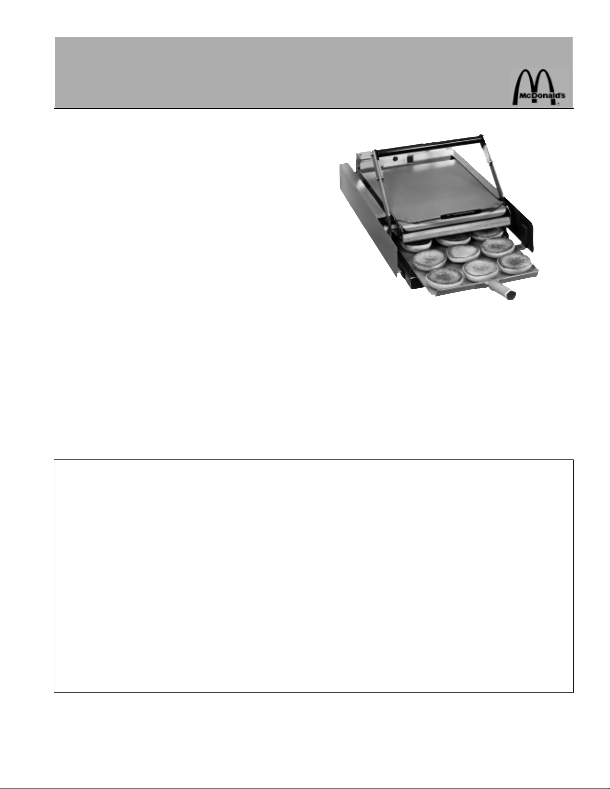
SOLID STATE DIGITAL TOASTER
PRINCE CASTLE MODEL NO. 213-NDB AND 213-NPDB SERIES
This equipment chapter is to be placed in the
toasters section of your Equipment Manual
MANUFACTURED FOR
MCDONALD’S
®
BY
PRINCE CASTLE INC.
355 KEHOE BLVD
CAROL STREAM, IL. 60188 USA
PHONE 1-630-462-8800
TOLL FREE NUMBER
1-800-323-2930
FAX:1-630-462-1460
WARRANTY ..................................................................................................................................................................................................... Page 1
SIDE VIEW ...................................................................................................................................................................................................... Page 2
FRONT VIEW .................................................................................................................................................................................................. Page 3
REAR VIEW ..................................................................................................................................................................................................... Page 3
INTERNAL VIEW ............................................................................................................................................................................................ Page 4
EQUIPMENT SETUP ..................................................................................................................................................................................... Page 5
PROGRAMMING ............................................................................................................................................................................................ Page 6
OPERATION AND CLEANING ...................................................................................................................................................................... Page 8
DIAGNOSTIC TROUBLESHOOTING ........................................................................................................................................................... Page 9
TROUBLESHOOTING ..................................................................................................................................................................................... Page 9
WIRING DIAGRAM ......................................................................................................................................................................................... Page 11
LIMITED WARRANTY
This product is warranted to be free from defects in material and/or workmanship for a period of (1)
year from date of original installation not to exceed 18 months from date of shipment from our factory.
Any part or component which proves to be faulty in material and/or workmanship within the warranty
period will be replaced or repaired without cost to the customer for parts or labor. (At the option of
Prince Castle, Inc.)
This warranty is subject to the following exceptions/conditions:
Any use of Non-genuine Prince Castle spare parts voids this warranty.
All labor should be performed during regular working hours. Overtime premium will not be covered.
The equipment is portable. Charges for on location service (e.g. trip charges, milage) are not in-
cluded in the provisions of this warranty.
Damage caused by carelessness, neglect, and/or abuse (e.g., using wrong current, dropping , tam-
pering with or altering electrical components, or improper cleaning) is not covered.
Equipment damaged in shipment, by fire, flood or an act of God.
This Manual is for the Exclusive use of Licensees and Employees of McDonald’s Systems, Inc.
1997 McDonald’s Corparation Printed in the
All Rights Reserved United States of America
Printed in October 1997
Part No. 213-544
Page 2
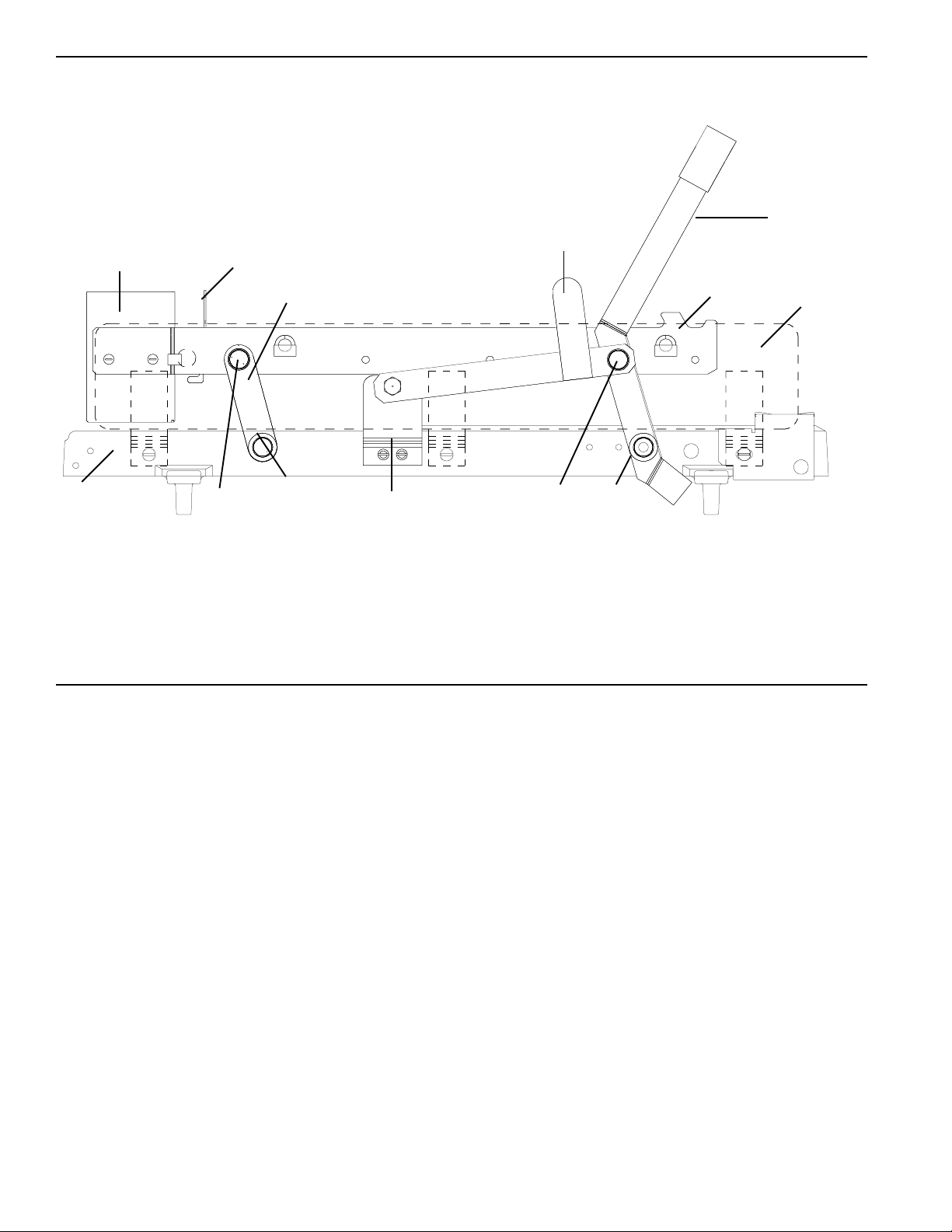
SIDE VIEW
7
1
2
6
8
PARTS LIST
10
5
11
3
9
10
11
4
ITEM PART NUMBER DESCRIPTION
1 213-124 Handle and Lever Assembly (With Bearings)
2 213-303 Safety Latch
3 213-616 Left Handed Bun Fence
213-615 Right Handed Bun Fence (Not Shown)
4 213-610 Side Panel (Both Sides)
5 212-303 Rear Lever Assembly (With Bearings)
6 416-763 Rear Bun Fence
7 213-704 Chassis
8 213-413S Base With Feet
9 213-305 Safety Latch Bracket
10 62-005 Upper Flange Bearing (Included With Lever Assy)
11 62-021 Lower Flange Bearing (Included With Lever Assy)
2
Page 3
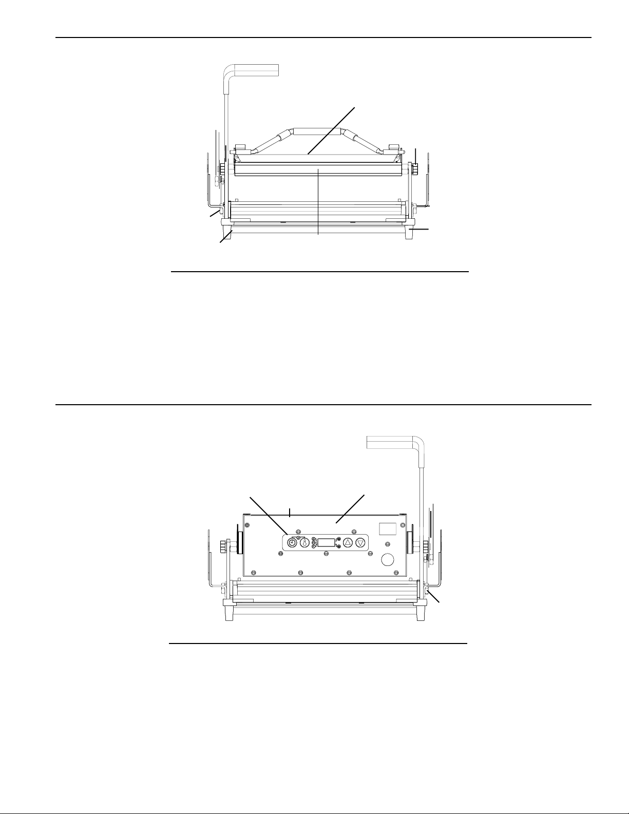
FRONT VIEW
1
2
2
3
3
4
4
5
PARTS LIST
ITEM PART NUMBER DESCRIPTION
1 213-492 "9/16" "Bun Board"
2 212-285 Platen Stud
3 212-284 Base Stud
4 89-959S Black Rubber Foot (Pkg of 4)
5 213-83 Platen
REAR VIEW
1
3
2
PARTS LIST
ITEM PART NUMBER DESCRIPTION
1 411-707 Overlay
2 213-704 Chassis
3 213-703 Face Plate
4 213-301 Pivot Bolt
5 213-306 L.H. Stop Block
213-307 R.H. Stop Block (Not Shown)
4
5
3
Page 4
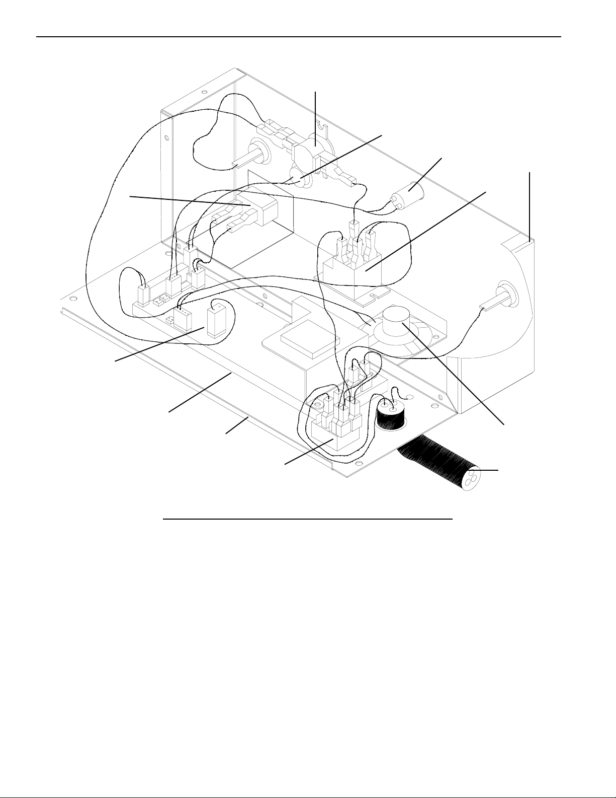
INTERNAL VIEW
8
11
12
4
3
9
2
1
7
5
6
PART LIST
ITEM PART NUMBER DESCRIPTION
1 & 2 411-426S Power Module
(Includes Power Board
and Display Board)
3 78-146S Timer Activating Switch
4 213-704 Chassis
5 213-703 Faceplate
6 78-166S Rocker Switch
7 88-430 Speaker Assy.
8 213-698 High Limit Thermostat
9 65-039S Relay
10 72-210S Power Cord Plug
72-212S Power Cord Plug (Overhead)
11 213-700S Temperature Probe
12 213-257S Bun Done Light
10
4
Page 5
SYMBOLS & TERMS
F - - A Toaster is set on Fahrenheit.
figure 2
C - - A Toaster is set on Celsius.
A L - Alarm Level setting 1-4.
Sound Button, used in conjunction with
timer button and temperature button to
set alarm level.
Timer Button, used to view time when in
the run mode and used to set time in the
program mode.
Temperature Button, used to view set
point temperature when in the run mode
and used to set the set point temperature
in the program mode.
Up Arrow, used when setting time, sound
and temperature when in the program
mode.
Down Arrow, used when setting time,
sound, and temperature when in the
program mode.
- L O
3 0 0
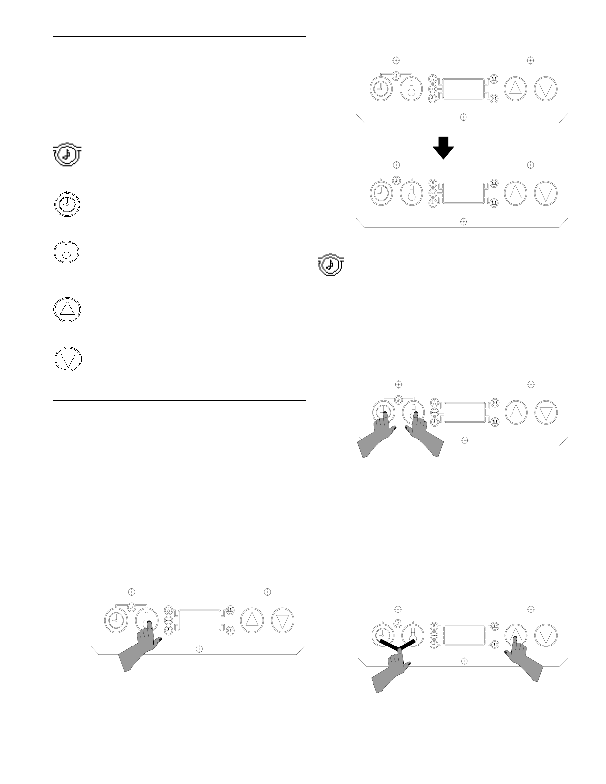
Sound Level Adjustment
The audio alarm has four sound levels. The
symbol for sound is the musical note.
1. Press and hold the time button while holding the
temperature button. The display will show the
current sound level. For example, A L 2 for Alarm
Level 2. See figure 3.
figure 3
SET-UP
1. Plug the toaster into a 110-120 volt grounded
receptacle. Turn on power switch and allow 30
minutes for warm-up.
2. During the initial power-up of the toaster the
display will read either F - - A for Fahrenheit or C
- - A for Celsius. Immediately the (A) will start to
count down from 9 to 0. During this nine second
period, holding the temperature button for six
seconds will change the display from F to C or C
to F as desired. See figure 1.
figure 1
F - -
3. After nine seconds, if no buttons are touched the
display will read - L O - until the platen temperature reaches 300° F (149° C). Then the display
show the actual platen temperature between 300°
and 500° F (149° & 260° C). See figure 2.
A L 2
2. While holding the time and temperature buttons,
press the up or down arrow buttons to adjust the
sound level. A continuous tone will sound.
Release all buttons when the desired sound level
has been reached. The display will show the
current temperature. See figure 4.
figure 4
A L 4
5
Page 6

VIEW SET POINT TEMPERATURE
1. Press and release the temperature button. The
press must be less than 6 seconds. A beep will
sound, the temperature indicator will turn on and
the display will show the set point temperature for 3
seconds. The display will then change to show the
actual temperature. See figure 5.
PROGRAMMING
The programming modes are used for setting an
individual set point temperature, calibrating the
toaster, and setting toast times.
Programming the Set Point Temperature
figure 5
SET POINT TEMPERATURE
4 5 0
ACTUAL TEMPERATURE
4 4 5
VIEW TIMER SETTING
1. Press and release the time button, but do not
hold for longer than 6 seconds. If the toaster is
not in a countdown sequence the set time will be
displayed for 3 seconds. If the toaster is in a
countdown sequence the time remaining will be
displayed, and will countdown to zero. After 3
seconds have passed it will return to showing the
temperature. See figure 6.
1. Press and hold the temperature button for six
seconds. A beep will sound, the indicator next to
the temperature symbol will blink, and the display
will show the current set point temperature.
See figure 7.
figure 7
4 5 0
2. To change the set point temperature use the up
or down arrows. Once the desired temperature is
showing in the display, press the temperature
button to store the new setting.
See figure 8.
figure 8
ADJUST SET POINT TEMPERATURE
4 4 0
figure 6
SET TIME
2 0
COUNTDOWN SEQUENCE
1 5
STORE SET POINT TEMPERATURE
4 4 0
3. To cancel out of the set point programming at any
time press and release the time button. The display
will change to show the actual temperature.
See figure 9.
6
Page 7

figure 9
4 4 5
3. To exit the time set function at any time press
and release the temperature button. The time
indicator will turn off and the display will change
to show the current temperature. See figure 12.
figure 12
Programming The Toast Times
1. Press and hold the time button for 6 seconds. A
beep will sound, and the indicator next to the
time symbol will blink. Release the time button
and the display will show the current toast time.
See figure 10.
figure 10
3 5
2. Use the up or down arrow buttons to set your
selected toast time. The range is from 20 seconds to 1 minute, 30 seconds. Once desired time
is reached press and release the time button to
store the new time. See figure 11.
4 4 0
SETTING STOP BLOCKS
The 213-NDB toaster leaves the factory with the stop
blocks set on number 3. The stop blocks are located
in the front of the toaster on the base on the right
and left side of the base. Stop blocks allow for
proper crush when toasting buns. To increase the
crush, set the stop blocks to number two setting. To
decrease the crush, set the stop block to the number
four setting. See figure 13.
figure 13
STOP
BLOCK
SETTING
figure 11
SETTING THE NEW TIME
2 0
STORING THE NEW TIME
2 0
IMPORTANT: The correct setting is when the lever is
touches the top of the number. The example above
shows a stop block setting of 1.
1. To change the setting on the stop block, disengage locking pin by depressing the right stop
block. Turn in either direction to correct setting.
7
Page 8

OPERATION
4. Lower the bun board onto the spatula. Make
sure the front lip of the bun board falls inbetween
rows which separate heels and crowns.
1. Once desired time and temperature are set, unit
is ready for toasting.
2. Place a total of six buns (Quarter or Regulars) on
the spatula. Make sure crowns are facing up ane
positioned in front of the notched markings on
the spatula. Position heels face down at farthest
end of spatula. See figure 14.
figure 14
HEELS
CROWNS
NOTCH
5. While holding onto the handle of the bun board,
slide spatula out of toaster. The bun board will
grab onto the heels and properly positions them
on the platen.
6. With the crowns still remaining on spatula, place
spatula on lower platform, making sure the
spatula is pushed all the way in.
7. Pull toaster handle forward to begin the toasting
cycle.
8. When timer sounds the toasting cycle is complete. Lift toaster handle all the way and remove
spatula with toasted crowns. While removing
spatula, lift bun board and pull it forward, sweeping heels onto spatula.
9. Stack the second row of heels on top of the first
row to retain heat.
10. Depending upon operational procedures, either
dress buns immediately, or stage them in a
heated cabinet.
3. Lift the bun board using the insulated handle.
Insert spatula between bun board and platen so
only heels are covered by the bun board.
See figure 15.
figure 15
CLEANING
1. Place the power switch in off position.
2. Unplug toaster.
3. Allow toaster platen to cool down.
4. Wipe entire platen clean with clean, damp grill
cloth. Full toaster cleaning must be done in the
morning when the toaster is cold. See your
Planned Maintenance Card for proper cleaning
procedures.
IMPORTANT: Do not drape cord over hot toaster bun
board or platen. This will cause cord to burn.
8
Page 9

DIAGNOSTIC TROUBLESHOOTING
If the toaster malfunctions, the display will flash an error code ( E 0 ) and a number between 1-9, or a letter
between A-F. Below are different error codes and there solutions.
1. Relay contacts are shorted: Check if relay is Shorted.
E 0 1
E 0 2
E 0 3
E 0 4
Platen over heating Check relay circuit
on power board.
2. Probe open or shorted: Replace probe.
Check probe connection.
3. Failures 1and 2 combined.
4. Platen not heating: Check for open relay.
Replace power/display board.
\
E 0 5
E 0 6
E 0 7
E 0 8
5. Failures 1and 4 combined.
6. Failures 2 and 4 combined.
7. Failures 1, 2, and 4 combined.
8. Probe amplifier circuit failure: Replace power/display.
9
Page 10

E 0 9
E 0 A
E 0 b
E 0 C
Failures 1 and 8 combined.
Failures 2 and 8 combined.
Failures 1, 2, and 8 combined.
Failures 4 and 8 combined.
E 0 d
E 0 E
Failures 1, 4, and 8 combined.
Failures 2, 4, and 8 combined.
10
Page 11

TROUBLESHOOTING GUIDE
PROBLEM CAUSE SOLUTION
Platen loose. Platen bolts loose. Tighten platen bolts.
Speaker sounds, but no Done light burned out. Replace done light.
bun done light comes on.
No speaker sounds Defective timer switch. Replace timer switch.
and bun done light. Timer connection shorted Replace power board.
does not come on. on power board.
Timer switch not activating. Check actuating bracket to
make sure it pushes
timer switch all the way in.
Buns being crushed. Stop blocks not adjusted Adjust stop blocks.
properly.
Warped bun trays. Straighten or replace bun
trays.
Buns cut improperly. Contact bakery.
Platen does not heat. No power. Check power source.
Power switch defective. Replace power switch.
Shorted power board. Replace power board.
Platen burned out or shorted. Check platen with ohmmeter
for 11 ohms, if reading is less
than 7 ohms or more than 14
ohms, replace platen.
WIRING DIAGRAM
11
Page 12

CARD NO.
Toasters
16
Planned Maintenance System
Maintenance Requirement Card (MRC)
Equipment: Bun Toasters: Solid State Digital
Precaution: During some checks, live electrical circuits will be exposed, and hot toasting
surfaces will be uncovered.
Hazard Communication Standard (HCS) - The procedures on this card include
the use of chemical products. These chemical products will be highlithed with
bold face letters followed by the abbreviation (HCS) in the tools portion of the
procedure. See the Hazard Communication Standard (HCS) Manual for the
appropriate Material Safety Data Sheet(s) (MSDS).
Weekly Applying Bun Toaster Release Agent
Tools: McD Bun Toaster Release Agent (HCS), customer paper napkins or paper
towels protective gloves, 257 cleaning tool.
IMPORTANT: Use only McD Toaster Release Agent on bun toasters. Other products
may damage bun toasters.
1. Dust all loose crumbs from toaster surfaces.
2. Toaster platens must be well rinsed and dry. McD Bun Toaster Release
Agentmay be applied to hot toaster platens. Before applying to hot platens, put
on protective gloves.
3. To coat top platen surface, thoroughly wet a clean, folded customer napkin or
paper towel, with Release Agent.
16
Monthly Check Calibration of Temperature
Tools: Digital thermometer with surface probe.
4. Rub a generous amount of Release Agent over entire surface of platen until
wellcoated,using protective gloves and No. 257 cleaning tool
5. Repeat steps 2 and 3 for other platens, including undersides.
IMPORTANT: Platen undersides and difficult to reach areas can be coated by
placing a folded customer napkin or paper towel with Release Agent on No. 257
cleaning tool to apply Release Agent to platen surface.
IMPORTANT: Do not wipe toaster with a damp cloth after Release Agent is ap-
plied. This removes Release Agent and causes sticking.
6. If sticking occurs between weekly applications, reapply Release Agent using
steps 1-4.
IMPORTANT: Apply Release Agent as directed above.
IMPORTANT: Toaster does NOT need to be recleaned or cooled down before
applying Release Agent.
IMPORTANT: Reapply Release Agent weekly, while toaster is cold, between
monthly cleaning, to all platen surfaces.
IMPORTANT: Do not calibrate until the toaster has been on for at least 45 minutes
and has stabilized.
1. Moniter the temperature of the platen being calibrated with a surface probe.
2. Enter the calibration mode by holding the TEMPERATURE, UP and DOWN
buttons for 6 seconds. A beep will sound and the indicator light next to the
CALIBRATION symbol will turn on. Release all buttons.
IMPORTANT: On two platen units (416 and 411) press and release the UP button to
calibrate the upper platen or use the DOWN button for the lower platen.
3. Allow the display 10 seconds to settle, and it will show the measured platen
temperature value with no offset. Use the UP and DOWN to adjust the display to
match the temperature reading on the digital thermometer surface probe.
4. Press the TEMPERATURE button to store the new calibrated temperature and to
exit the calibration mode. The indicator next to the calibration symbol
will turn off, after 10 seconds the new calibrated temperature will be displayed.
<>
<>
Card 16
Page 13

Monthly Clean Nickel Platen
Tools: McD Hi-Temp Grill Cleaner (HCS), McD Bun Toaster Release Agent (HCS), McD
No-Scratch Pad, base of Big Breakfast container, No. 257 cleaning tool, clean grill
cloths (qty. 6-8), customer paper napkins or paper towels, protective gloves.
PREPARING BUN TOASTER
1. If toaster is cool, heat to operating temperature.
IMPORTANT: Bun toaster must be at operating temperature for cleaning.
2. Turn toaster power switch to OFF position and unplug power cord.
CAUTION: Failure to unplug power cord before cleaning
may cause electrical shock.
3. Remove all buns, bun trays, and bun tray liners from the bun toaster stand.
4. Turn on the grill exhaust fan.
5. Move toaster stand in front of grill.
HOW TO CLEAN
1. Firmly attach McD No-Scratch Pad to cleaning tool. Use only nonabrasive blue
No-Scratch pad used for grill cleaning. Do not use a green pad. It will damage
platen surface.
2. Pour one packet of McD Hi-Temp Grill Cleaner into a breakfast container base.
3. Put on protective gloves.
4. Turn bun board upside down and lay on upper platen or plate.
5. Dip No-Scratch Pad into Hi-Temp Grill Cleaner.
6. Spread cleaner over bun board and lightly scrub until clean. Apply additional
cleaner as needed. Place bun board in the back sink area for cooling and
rinsing.
7. Repeat Step 6 for both sides of aluminum plate if toaster is equipped with one.
8. Dip No-Scratch Pad into cleaner and lightly spread a coasting of cleaner onto
top surface of platen.
IMPORTANT: Do not pour cleaner on surface. Apply only with No-Scratch Pad
and Cleaning Tool. Do not scrub while applying cleaner.
9. Repeat Step 8 for all platen surfaces, including undersides.
10. After applying cleaner, lightly scrub all platen surfaces (including undersides)
with No-Scratch Pad until all soil liquefies. Apply additional cleaner to cleaning
pad as needed.
11. Remove No-Scratch Pad from cleaning tool. Fold a clean, damp grill cloth
lengthwise and lay over end of cleaning tool. Thoroughly rinse platens, including
undersides, by wiping with a damp grill cloth. Each time before wiping platens,
rinse grill cloth in clear water and wring out until no soil is seen.
IMPORTANT: Thorough rinsing of platen is required to ensure proper release
agent performance. Rinse platens with clean grill cloths until no soil is seen on
the cloth.
CAUTION: Do not pour water on platens
or use dripping wet grill cloths.
12. Repeat the rinsing procedure in Step 11 with a fresh, clean, damp grill cloth to
ensure all cleaner and soil are removed from platens.
13. Wipe remaining parts of toaster with a clean damp cloth.
14. Take bun tray platform, bun board, and aluminum plate to back sink. Scrub with
a pot brush or No-Scratch Pad in a solution of McD All Purpose Concentrate.
Do not use abrasive pads. Rinse parts under running water and let air dry.
Card 16
Page 14

Monthly Tighten Platen and Leg Bolts
Tools: Adjustable wrench, flatblade screwdriver
TIGHTEN PLATEN BOLTS
1. Turn the power switch to the OFF Position.
2. Unplug the power cord.
3. Allow the toaster to cool before proceeding.
4. Using an adjustable wrench, tighten the platen bolts which hold handle in upright
position.
TIGHTEN LEG BOLTS
5. Carefully turn the toaster upside down for access to the legs.
6. Adjust and tighten leg bolts to obtain a level setting for toasting.
7. Set toaster right side up and check for a level setting.
8. Adjust leg bolts as necessary until toaster sits level.
9. Plug the power cord into the appropriate electrical receptacle.
10. If the toaster is about to be used, turn the power switch to the ON position.
Monthly Check Bun Tray Platforms, Bun Board, Bun Trays and Spatulas
Tools: Pliers, hammer, file
IMPORTANT: This check procedure should be conducted while the platforms, trays and
spatulas are cold. It should be done for all spatulas, trays and platforms.
BUN SPATULA
1. Lay the spatula on a flat work table top.
2. Make sure the entire surface is flat, including the front edge. The front end of
the bun spatula must be free from necks and burrs.
3. Sharpen front edge of spatula so all nicks and burrs are removed.
IMPORTANT: Straightening can be accomplished with a pliers or a hammer.
BUN TRAY
4. Lay the tray on a flat work tabletop and inspect for flatness.
5. Inspect the tray for uniform height.
6. Straighten curled corners with pliers and hammer middle part of tray flat.
BUN TRAY PLATFORM
7. Remove the platform from the lower part of the toaster.
8. Lay the platform on a flat work tabletop and inspect the entire surface to make
sure it is flat.
9. Using pliers or a hammer, straighten as needed.
10. Reinstall the platform into toaster.
BUN BOARD
11. Remove the bun board from toaster.
12. Lay the bun board on a flat work tabletop and inspect for flatness.
13. Measure the distance between the tabletop and the bottom side of the bun
board in the front, center, and rear. It should be approximately 1/2” (13 mm) for
all toasters except Big Mac 412 and 416 series, and approximately 3/4” (19 cm)
for Big Mac Toasters.
14. Bend as needed to maintain flatness.
Card 16
Page 15

CARD NO.
Toasters
17
Planned Maintenance System
Maintenance Requirement Card (MRC)
Equipment: Bun Toasters: All
Precaution: Ensure electrical plug is removed before working inside the unit.
PICTURES AND ADDITIONAL INFORMATION: Corresponding chapter of Equipment Manual
Quarterly Clean Electrical Box and Check for Tightness of Connections
Tools: Flatblade screwdriver
1. Turn the power switch to the OFF position and unplug the power cord. Allow toaster
to cool.
2. Loosen and remove the screws along the rear panel and on the cover of the electrical box.
3. Gently pull the rear panel away from the toaster (until restrained by the wires) and lift
cover off electrical box.
4. Remove all loose crumbs and debris from the electrical box and visually inspect for
frayed wires or loose connections.
IMPORTANT: The terminals and connectors will appear burned or darkened due to
arcing if they are loose.
5. Connect and tighten all wires. Put electrical panel and cover back in place and
tighten screws.
6. Plug toaster in and turn power switch ON.
17
1 of 1
1997 McDonald’s Corporation
All Rights Reserved
Printed in September
Card 17
 Loading...