

Page 1
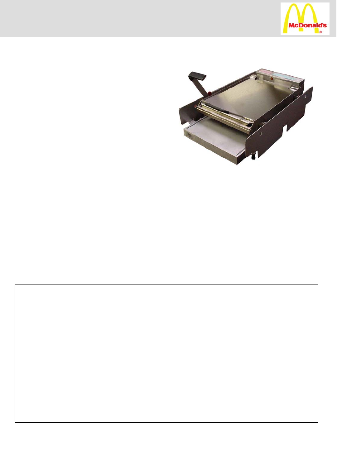
REGULAR BUN TOASTER
PRINCE CASTLE MODEL 213-LFMCEC SERIES
213-LFKC SERIES AND 213-LFALC (AUSTRALIA)
This equipment chapter is to be placed in the
Toasters section of your Equipment Manual.
MANUFACTURED
EXCLUSIVELY FOR
McDONALD’S®
BY
PRINCE CASTLE, INC.
355 E. KEHOE BLVD.
CAROL STREAM, IL 60188 U.S.A
PHONE: 1 (630) 462-8800
TOLL FREE NUMBER:
1 (800) 323-2930
FAX: 1 (630) 462-1460
TABLE OF CONTENTS
WARRANTY. . . . . . . . . . . . . . . . . . . . . . . . . . . . . . . . . . . . . . . . . . . . . . . . . . . . . . . . . Page 1
INTRODUCTION. . . . . . . . . . . . . . . . . . . . . . . . . . . . . . . . . . . . . . . . . . . . . . . . . . . . . Page 2
PARTS IDENTIFICATION AND FUNCTION. . . . . . . . . . . . . . . . . . . . . . . . . . . . . Page 2
EXPLODED VIEW. . . . . . . . . . . . . . . . . . . . . . . . . . . . . . . . . . . . . . . . . . . . . . . . . . . . Page 5
EQUIPMENT SET-UP AND CLOSE PROCEDURES. . . . . . . . . . . . . . . . . . . . . . . Page 6
TROUBLESHOOTING GUIDE. . . . . . . . . . . . . . . . . . . . . . . . . . . . . . . . . . . . . . . . . .Page 7
ORDERING PARTS/SERVICE. . . . . . . . . . . . . . . . . . . . . . . . . . . . . . . . . . . . . . . . . . Page 8
NON-SCHEDULED MAINTENANCE. . . . . . . . . . . . . . . . . . . . . . . . . . . . . . . . . . . . Page 9
WIRING INFORMATION. . . . . . . . . . . . . . . . . . . . . . . . . . . . . . . . . . . . . . . . . . . . . . Page 28
WARRANTY
This product is warranted to be free from defects in materials and/or workmanship for a period
of 12 months from date of purchase.
Any part or component which proves to be faulty in material or workmanship within 12 months
from date of purchase will be replaced or repaired (at the option of Prince Castle, Inc.) without
cost to the customer for parts and labor.
This warranty is subject to the following exceptions/conditions:
1) This equipment is portable; charges for on-location service (e.g. trip charges, mileage)
are only included in the provisions of this warranty for a failure which occurs within 30
days of installation.
2) Damage caused by carelessness, neglect, and/or abuse (e.g. using wrong current,
dropping, tampering with or altering electrical components) voids this warranty.
This manual is for the exclusive use of licensees and employees of McDonald’s Systems, Inc.
©2003 McDonald’s Corporation Printed in
All Rights Reserved The United States of America
Printed in February
Part No. 213-534RevA
EM T2
Page 2

INTRODUCTION
The regular bun toaster caramelizes 12
complete regular buns or ¼ lbs. buns in 55
seconds when using flat grills, or in 35 seconds
when using clamshell grills.
The crowns are placed on a bun tray containing
a paper tray liner and put into the bottom of the
toaster. When using 55 second toast, the heels
are placed on top of the platen under the bun
PARTS IDENTIFICATION AND FUNCTION
PART
NO.ITEM
board, when using 35 second toast, heels are
placed on the ¼ “ (6 mm) aluminum plate,
resting on top of the platen. The handle is
pulled down, lowering the platen onto the top
of the crowns, (This also activates the timer),
After 55 seconds, or 35 seconds depending on
the type of grill being used, a buzzer will sound
and a bun ready light will come on indicating the
end of the toasting cycle.
FUNCTIONQTY.DESCRIPTION
Holds stop blocks to toaster frame1Stop Block Rod416-292
1Washer, Notched213-1644
1Stop Blocks (L.H. & R.H)213-306S6
1Spring Bracket212-2278
4Rubber Foot89-595S10
2Rear Lever with Bearings212-701S 13
4Bearing62-00514
4Bearing62-02115
Locates the position of the stop blocks to
the front levers and holds the
compression spring in position.
Holds stop blocks in position. 1Compression Spring81-0095
Adjusts the height of the platen. 6 stop
positions from 35/64” to 1 11/64” (14
mm to 32 mm) on the bun crowns
Mounts to the frame and holds helper
springs.
Maintains alignment of levers and platen.4Spacer212-283S9
Elevates toaster to allow proper air
circulation and cleaning.
Holds the rear of the platen in the toaster
and allows for opening and closing the
toaster.
Aligns bearing studs in handle and lever
assemblies
Aligns bearing studs in handle and lever
assemblies.
4Bearing Stud212-284S16
2Bearing Stud212-286S18
2
Holds the front and rear levers to the
toaster frame.
Stud that holds the levers to platen4Bearing Stud212-285S17
Stud that holds the front lever to the
platen and connects to helper spring.
Page 3

PART
NO.ITEM
FUNCTIONQTYDESCRIPTION
Holds the platen in the toaster and allows
1Front Lever with Bearings213-12419
for raising and lowering the platen.
Helper spring to reduce lifting force1Spring215-7 20
Attaches to side of toaster platen and holds
1Spring Link416-1321
helper spring
Safety latch engaged attachment location1Platen Stud Safety Latch213-304S22
Mounts to the frame to protect hands from
2Side Panel213-41623
touching the platen.
Attachment and pivot point for the safety
1Pivot, Safety Latch213-30125
latch.
When engaged holds the platen in the open
1Safety Latch213-30327
(up) position.
213-671
213-24540
Bracket, Safety Latch213-30528
Bun Board (213-LFMNCE
only)
Tube
Attaches and positions the latch to the
1
frame.
Attached to the platen to prevent buns
1L.H. Bun Fence213-64230
from falling off the sides.
1R.H. Bun Fence231-64431
Electrically heated toasting surface1Platen Kit213-8432
Attached to the platen to prevent buns
1Upper Rear Bun Fence213-65133
from falling off the back.
Used as a bun weight to compress the
1Bun Board213-38834
heels to the platen for proper toasting.
Removable--allows access to enclosure1Cover212-22037
Insulators that protect the heating element
3Platen Tube213-36439
connectors and thermostat capillary tube.
Holds platen tubes in place.12Retainer—Thermal Break
Maintains and controls heat.1Thermostat222-122A42
Used to adjust thermostat1Knob222-102S44
Starts the timer for toasting cycle1Timer Switch Kit78-146S45
Protects the switch from touching metal1Switch Insulator416-4346
Lights when toasting cycle has completed1Amber Bun Ready Light71-134-147
Indicates power to the toaster. 1White Power Light71-134-248
3
Page 4

PART
NO.ITEM
416-259SC
72-196S57
second
(Europe only)
Plug only (Europe)88-566S
FUNCTIONQTYDESCRIPTION
Goes ON when platen is heating1Green Temp Light71-134-3C49
Turns unit ON and OFF1Power Switch78-166S50
Indicates when buns are done. 1Buzzer212-35252
Protects buzzer from touching metal1Buzzer Insulator212-24054
Controls toasting time (nonadjustable)
135 Second Timer88-445C55
solid state.
155 Second Timer88-151C
Controls toasting time (adjustable for
1Timer Assembly 35/55
either 35 second or 55 second).
Secures power cord to toaster face plate1Strain Relief66-045S56
Transfers electrical currently from
1Power Cord with Plug
electrical outlet to toaster.
Secures power cord to toaster frame to
1Strain Relief Bushing66-03758
prevent fraying.
212-33159
Heat Sink (optional)1¼” (6 mm) Aluminum
Plate
4
Page 5
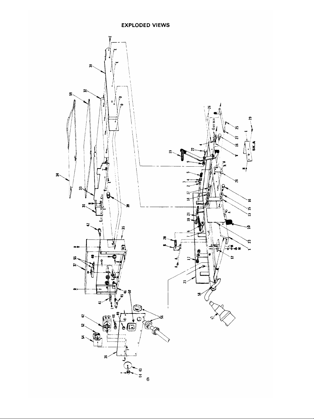
5
Page 6
EQUIPMENT SET-UP AND
CLOSE PROCEDURES
6. Ensure stop blocks are on correct setting.
(See Figure A)
Set-up
• See MRC 16 for proper cleaning procedures.
CAUTION: Before plugging in, make sure
toaster is turned OFF.
1. Insert the power plug into a 16 Amp grounding
receptacle.
2. Place the power switch in the ON position.
3. Pull operating handle/link assembly forward and
down. This will activate timer assembly. After 55 ± 5
seconds, (or 35 ± 1 second when used with the
clamshell grill) buzzer will sound and “Bun Ready
Light” will come ON. Lift operating handle/link to
deactivate.
4. Ensure platen is in the up position while the toaster
warms up so that the timer is not activated.
5. Allow the toaster to warm up. Specific equipment
warm up times are in the Operations and Training
Manual.
Left Side
Panel
1
Stop
Block
2
3
Pin Stop
Bracket
FIGURE A
NOTE: To change setting of stop block, depress
the right stop block to disengage locking pin and
turn in either direction to correct setting.
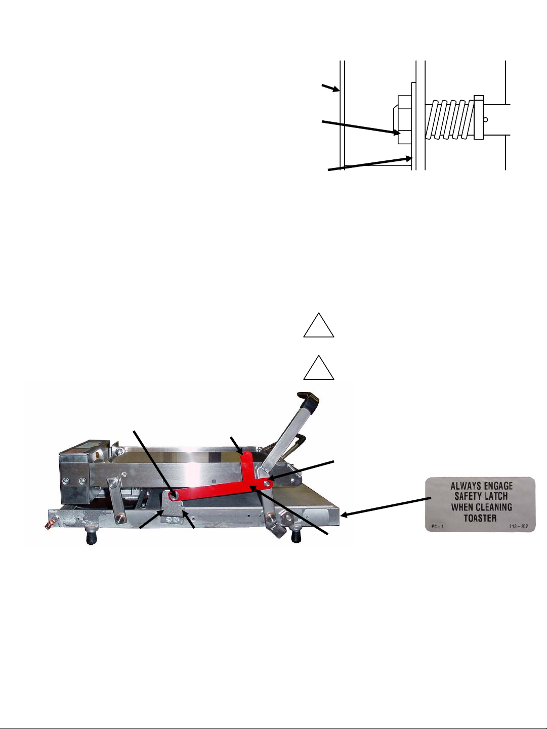
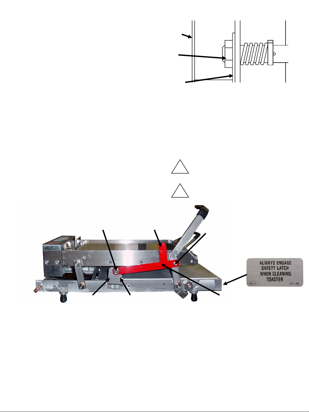
7. Unlock handle by moving safety latch from the
platen stud to the “UNLOCKED” position.
(See Figure B)
This appliance is not of water tight
!
construction. Do not clean this appliance
with a water jet/spray.
MOUNTING BOLT SAFETY
SAFETY LATCH
BRACKET
LATCH
STOP
TAB
Figure B
8. To convert toaster (35 sec.) to (55 sec.),
remove aluminum plate from top of platen.
Turn 35-55 second timer select switch, located
underneath electrical box, to 55 second position
Recalibrate platen temperature from 420°F
(216°C) ±5°F (±3°C) to 400°F (204°C) ±5°F
(±3°C).
!
Do not immerse appliance in water.
SAFETY
SAFETY LATCH
BEARING STUD
LOCKED
POSITION
LATCH
LABEL
Close
CAUTION: Before unplugging, make sure
toaster is turned OFF.
1. Place the power switch in the OFF position.
2. Unplug toaster.
3. Allow toaster platen to cool.
4. Wipe entire platen clean with clean damp
grill cloth. Full toaster cleaning must be done
in the morning when the toaster is cold.
NOTE: Aluminum plate must be removed
prior to calibration.
CAUTION: Do not drape cord over hot toaster
6
bun board or platen as it will burn cord.
Page 7

TROUBLESHOOTING GUIDE
NOTE: Service is to be performed by qualified
service personnel.
WARNING: Inspection, testing and repair of
electrical equipment should be performed
only by qualified service personnel. The unit
Done light
Ready light.
goes on but buzzer does
not work.
should be unplugged when servicing, except
when electrical tests are required.
DANGER: Use extreme care during electrical
circuit tests. Live circuits will be exposed.
CORRECTIVE ACTIONPROBABLE CAUSEPROBLEM
Tighten platen bolts. See MRC 16Platen bolts loose. Platen loose
Replace light.Light burned out. Buzzer works, no Bun
Replace timer switch. Defective timer switch.No buzzer or Bun
Replace timer assembly.Defective timer assembly
Adjust timer switch stroke. Timer switch not adjusted.
Replace buzzer.Buzzer burned out. Amber Bun Ready light
at 35 seconds rather
than 55 seconds.
Bun heels not toasting
properly on 35 or 55
second toast.
Timer assembly set incorrectly. Timer assembly sounds
second toast.
Adjust stop blocks.Stop blocks not adjusted properly. Buns being crushed.
Straighten or replace bun trays. Warped bun trays.
Contact bakery. Buns cut improperly.
Straighten or replace bun platform. Warped bun platform.
Check power source. No power. Platen does not heat.
Replace power switch. Power switch defective.
Correct as necessary. See MRC 17.Loose wiring.
Replace thermostatDefective thermostat
Replace platen. Call service agency. Platen burned out or shorted.
Recalibrate thermostat. See MRC 16.Excessive heat. Buns sticking to platen.
Clean platen. See 16.Build up of sugar on platen.
Check position of timer select switch.
Set it at 55 seconds. Recheck time.
Replace plate. Aluminum plate missing on 35
Change bun board item #35. Wrong bun board being used.
7
Page 8

ORDERING/SERVICE IMFORMATION
Contact your kitchen Equipment Supplier or
designated repair facility for parts and service.
1. PARTS RETURNS
Should the need ever arise to return parts
to your Center for credit, it is necessary that
you:
• Obtain authorization from your Service
Center for such return;
• All warranty situations should be handled
by your Service Center.
B. All prices are subject to change without
notice. These prices are exclusive of all
sales taxes or any special taxes which
may be levied by federal, state or city
governments.
3. TERMS
Net 30 days.
INSPECT
CARTON
2. PRICES:
A. All prices are F.O.B Prince Castle Service
Center or F.O.B. factory, Carol Stream,
Illinois.
Remove product from carton . . . .
If damaged:
• Notify carrier
• Save carton and packing material
• Contact Prince Castle Customer Sales
for replacement.
8
Page 9

NON-SCHEDULED MAINTENANCE
ELECTRICAL REPAIRS
Under normal conditions with proper use and cleaning,
very little non-scheduled maintenance will be required
for this toaster. However, this section provides procedures for checking and replacement of the various
parts used within the toaster in the event that it becomes
necessary. Before replacement of any parts refer to
the Troubleshooting section for assistance in determinating the cause of any malfunction.
GENERAL INSTRUCTIONS
Whenever you disconnect any electrical wires mark
them in some way that will indicated to you which
terminal they came from. Do not disconnect too many
electrical connections at one time. Should you forget
where a wire connects, refer to the individual wiring
diagram for the particular control being replaced.
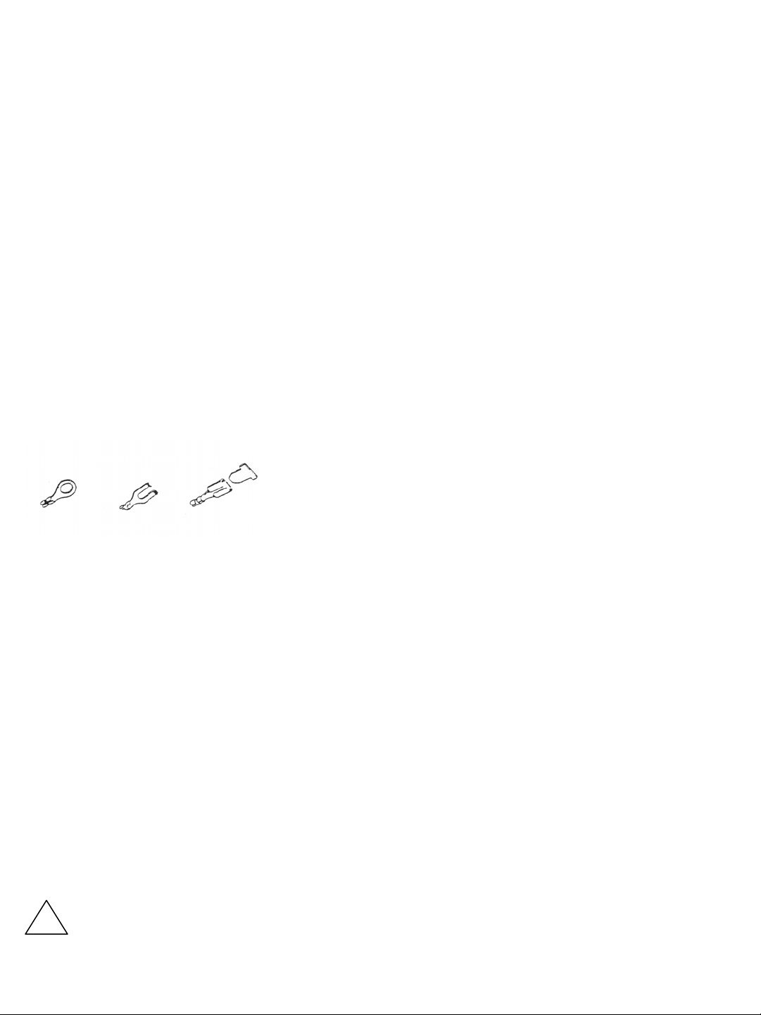
You will note that there are three basic methods of
affixing wires to their terminals:
(1) closed eye;( 2) spade; (3) knife and blade
STANDARD PROCEDURE FOR ALL ELECTRICAL
REPARIS: PLACE POWER SWITCH IN OFF POSITION & UNPLUG TOASTER.
When replacing any electrical controls mounted
in the control box, the disassembly of the following is standard procedure (except where noted):
A. Remove 2 screws from electrical box cover.
B. Remove cover.
C. Remove 6 screws from faceplate.
REPLACE PLATEN
This procedure should be done by a qualified
service technician.
REPLACE LIGHTS
1. Locate inoperable light.
2. Disconnect the 2 wires from the light.
3. Remove the light by squeezing the bezel clips
while pulling the light away from the control
panel.
4. Reverse procedure to install new light.
DO NOT WRAP BARE WIRE UNDER A TERMINAL HEAD SCREW, USE PROPER TERMINALS.
Before attempting to repair your toaster, you must:
A. Turn OFF and unplug toaster.
B. Disconnect electrical supply
WARNING: Failure to do so will result in
electrical shock.
C. Permit the unit to cool completely.
Finally: Make good use of the “Explode View”
and parts pictures in this chapter to further aid
you in understanding the physical make-up of
your toaster and the re-assembling of its
components.
The power cord shall only be replaced with an oil resistant rubber
!
type cord that has a minimum
temperature rating of 90°C.
REPLACE POWER SWITCH
Tools: Flatblade screwdriver.
1. Turn OFF and unplug toaster.
WARNING: Failure to do so will result in electrical shock.
2. Remove power switch by squeezing Bezel
clips on switch and pushing switch out of
control box.
3. Remove wires from switch. Refer to wiring
diagram for wiring connections.
4. Replace by reverse procedure.
REPLACE POWER CORD
Tools: Flatblade screwdriver
1. Turn OFF and unplug toaster.
WARNING: Failure to do so will result in
electrical shock.
2. The power switch will have to be removed
to get at the power cord wires that connect to
the bottom terminal.
9
Page 10

3. Disconnect green/yellow ground wire from
face plate.
4. Disconnect brown wire from the power
switch.
5. Disconnect blue neutral wire from top of
power switch for 115V units. For 200/220V
units, disconnect blue neutral wire from
bottom of power switch.
6. Remove cord from faceplate by removing
strain relief bushing.
7. Reverse procedure to re-install power cord.
REPLACE BUZZER (See Figure 4)
Tools: Flatblade screwdriver.
1. Turn OFF and unplug toaster.
WARNING: Failure to do so will result in
electrical shock.
2. Remove screw holding buzzer to faceplate.
3. Cut 2 wires from buzzer.
4. Strip about ½” (13 mm) of insulation from
each end of the wires that were cut.
5. Connect new buzzer with wire nuts.
REPLACE THERMOSTAT
(See Figure 4)
Tools: Fladeblade screwdriver
1. Turn OFF and unplug toaster.
WARNING: Failure to do so will result in
electrical shock.
2. Unscrew retaining nut on outside of
electrical box.
3. Remove switch from electrical box.
4. Remove 2 wires from thermostat terminals.
5. Remove thermostat bulb retainer from
electrical box.
6. Remove thermostat and sensing bulb.
7. Replace with new thermostat by reverse
procedure making sure to coat new thermostat bulb with thermo-coat provided.
8. Calibrate as outline on Planned Maintenance Card 16.
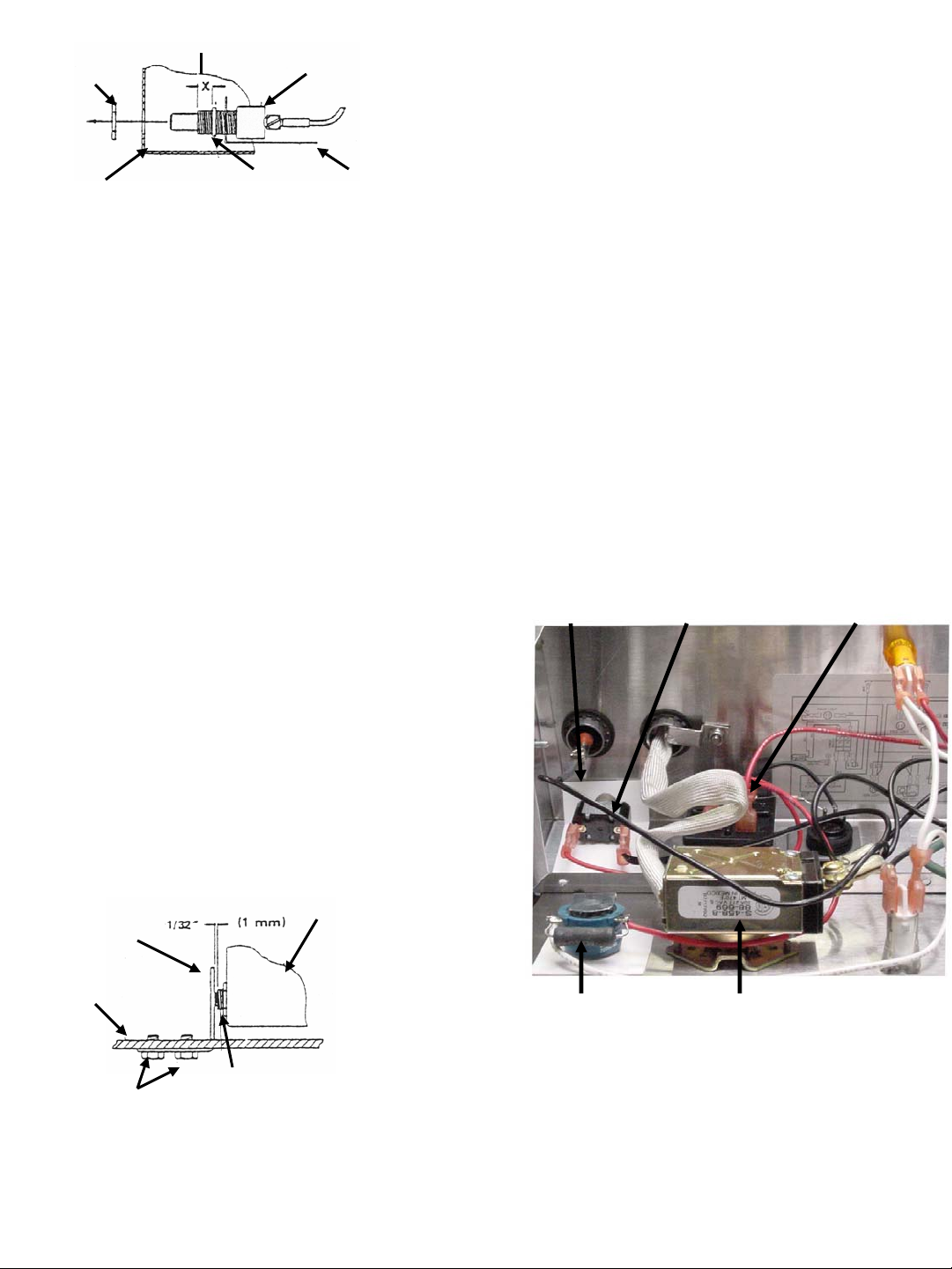
REPLACE TIMER SWITCH
(See Figure 2 & 4)
Tools: Flatblade screwdriver
1. Turn OFF toaster and unplug
WARNING: Failure to do so will result in
electrical shock.
2. Unscrew retaining nut on outside of
electrical box.
3. Remove switch from electrical box.
4. Remove retaining ring and insulator from
switch.
5. Remove 2 wires from switch.
6. Mount 2 wires on new switch.
7. Insert new switch into insulator.
8. Position retaining ring on new switch
¼” (6 mm) from end of bushing.
NOTE: Insulator should be placed between
switch body and retaining ring. (See Figure 2)
10
Page 11
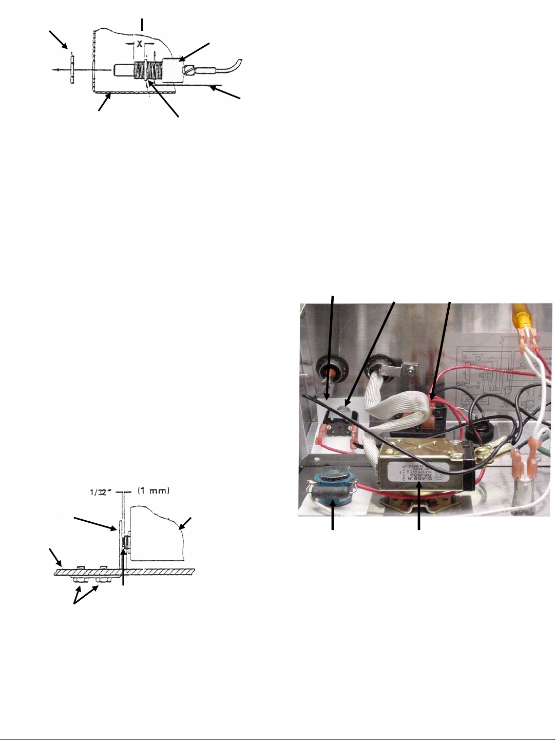
¼” (6 MM)
RETAINING NUT
ELECTRICAL BOX
Figure 2
SWITCH BODY
INSULATOR
RETAINING RING
9. Install new switch into electrical box and
tighten retaining nut on outside of
electrical box.
10. Set stop blocks at lowest position.
11. Lower platen slowly and watch movement
of new switch against actuator bracket.
NOTE: When platen is all the way down, there
should be no more than a 1/32” (1 mm) clearance
between threaded switch bushing and
actuator bracket.
REPLACE TIMER ASSEMBLY
(See Figure 4)
Tools: Flatblade screwdriver
1. Turn OFF and unplug toaster.
WARNING: Failure to do so will result in
electrical shock.
2. Remove 2 wires from timer assembly.
3. Remove screw and nut holding timer
assembly to bottom of electrical box.
4. Remove timer assembly.
5. Replace with new timer assembly by
reverse procedures.
INSULATOR
TIMER
SWITCH
TIMER
ASSEMBLY
NOTE: The threaded switch bushing must not
press against the actuator bracket.
12. To adjust actuator bracket, loosen mounting screws and move bracket until 1/32”
(1 mm) clearance is attained as shown in
Figure 3 below. Re-tighten mounting
screws when bracket is in position.
ACTUATOR
BRACKET
FRAME
THREADED SWITCH BUSHING
MOUNTING SCREWS
Figure 3
ELECTRICAL BOX
BUZZER THERMOSTAT
Figure 4
13. Tighten retaining nut against chassis to
prevent movement.
11
Page 12
MISE EN PLACE DE L’APPAREILET
PROCÉDURES DE MISE HORS TENSION
6. Assurez-vous que les butêes de sécurité sont
correctement réglées. (Voir Figure A)
Mise en place
• Voir MRC 16 pour les techniques de nettoyage
correctes.
ATTENTION: Avant de brancher l’appareil,
assurez-vous que le grille-pain est éteint (OFF).
1. Branchez le cordon d’alimentation sur une prise mise à la
terre de 16 amp. Placez l’interrupteur principal sur “ON”
(MARCHE).
2. Placez l’interrupteur principal sur ON.
3. Tirez sur la manette/amillon vers l’avant et vers le bas.
Vous enclencherez ainsi la minuterie. Après 55 ±5
secondes, (ou 35 ± 1 secondes lorsque utilisée avec le gril
à double coque) un avertisseur sonore retentira et le
voyant indiquant que les pains sont prêt s’allumera (ON).
Soulevez la manette/mailion pour mettre hors circuit.
4. Assurez-vous que la presse est droite pendant que le
grille-pain chauffe afin d’éviter de mettre en marche la
minuterie.
5. Laissea chauffer le grille-pain. Les temps d’échauffement
de certains appareils se trouvent dans la notice
d’exploitation et d’entraînement.
Panneau
Gauche
Butée
De Sécurité
Support De
La Butée
De Clavette
REMARQUE: Pour modifier le réglage de la butée
7. Débloquez la manette en plaçcnt le goujon
!
!
1
2
3
de sécurité, appuyez sur la butée droite afin de
relâcher le boulon de fixation et tournez pour
régler.
de la presse sur la position “UNLOCKED”
( NON FERMÉE). (Voir Figure B)
Cet appareil n’est pas etanche. Ne pas
nettoyer cet appareil au jet d’eau ou avec
nettoyeur haute pression.
Ne pas placer cet appareil dans de l’eau.
BOULON
DE MONTAGE
SUPPORT DU LINGUET
DE SÉCURITÉ
CRAN
DE SÉCURITÉ
8. Pour transformer le grille-pain (35 sec.) en
grille-pain (55 sec.), retirez la plaque
d’aluminum (article 59) du dessus de la presse.
Tournez le bouton de sélection des minuteries
35-55 seconds situé sous la boîte electrique afin
de le placer sur la position 55. Réglez à
nouveau la température de la presse de 420°F
(216°C) ±5°F (±3°C) to 400°F (204°C) ±5°F
(±3°C).
REMARQUE: La plaque d’aluminium doit être
retirée avant l’étalonnage.
LINGUET
DE SÉCURITÉ
ANCRAGE
DU LINQUET
DE S
ÉTEQUETTE
DU LINGUET
DESÉCURITÉ
POSITION
FERMÉE
Fermeture
Attention: Avane de dêbrancher l’appareil,
assurez-vous le grille-pain est éteint (OFF).
1. Éteignez l’appareil en plaçant l’interrupteur
principal ser OFF.
1. Débranchez le grille-pain.
2. Laissez refroidir la presse du grille-pain.
3. Essuyez entiérement la presse à l’aide d’un
chiffon propre et humide. Nettoyez entiérement
le grille-pain le matin lorsque cer dernier est
froid.
Attention: Ne pas faire passer le cordon
d’alimentation sur la plaque des petits pains
ou sur la presse car vous brûlerez ce dernier. 12
Page 13

GUIDE DE DÉPANNAGE
REMARQUE: Tout service d’entretien doit être
effectuê par du personnel qualifié.
AVERTISSEMENT: Faîtes faire essai, révision ou
réparation par du personnel qualifié. Débrachez
de voyant indiquant que les
pains sont cuits.
Pas d’avertisseur sonore ni de
voyant.
Le voyant ambre s’allume
mais pas d’avertisseur sonore.
défectueux.
réglé.
fonctionnement..
l’appareil pour toute opération d’entretien
excepté. lorsque des essais électriques sont
nécessaires.
DANGER: Faîtes preuve d’une extrême
prudence lors des essais électriques. En effet,
des circuits sous tension risquent d’être à
découvert.
SOLUTIONCAUSE PROBABLEPROBLÉME
Serrez les boulon de la presse. Voir MRC 16Les boulons de la presse sont desserrés. Presse desserrée.
Remplacez le voyant.Voyant grillé. Avertisseur sonore mais pas
Remplacez l’interrupteur de la minuterie. L’interrupteur de la minuterie est
Remplacez la minuterie.La minuterie est défectueuse
Réglez pas de l’interrupteur de la minuterie.. L’interrupter de la minuterie n’est pas
Remplacez l’avertisseur sonore.Avertisseur sonore hors d’état de
Les petit pains sont écrasés.
collés à la presse.
secondes au lieu de 55
secondes.
réglées correctement.
Les plateaux des petits pains sont
déformés.
La plate-forme des petits pains est
déformée.
Le thermostat est défectueux.
Les presse est grillée ou il y a eu courtcircuit.
Chaleur excessive. Les petit pains demeurent
La minuterie a été mal réglée. L’avertisseur sonne à 35
Réglez les butées de sécurité.Les butées de sécurité ne sont pas
Redressez ou remplacez les plateaux des petits
pains.
Contactez la boulangerie. Les petits pains ont été mal coupés.
Redressez ou remplacez la plate-forme des
petits pains.
Vérifiez l’alimentation électrique. Pas de courant. La presse ne chauffe pas.
Remplacez l’interrupteur principal. L’interrupteur principal est défectueux.
Corrigez comme il se doit. Voir MRC 17.Le câblage est desserré.
Remplacez le thermostat. Appelez l’agence
réparatrice.
Remplacez la presse. Appelez l’agence
réparatrice.
Étalonnez à nouveau le thermostat. Voir MRC
16.
Nettoyez la presse. Voir MRC 16.Accumulation de sucre sur la presse.
Vérifiez la position de l’interrupteur de
sélection de minuterie. Réglez-le à 55 seconds.
Vérifiez à nouveau le temps affiché.
Les croûtons des petits pains
ne grillent pas correctement
quel que soit le réglage (35 ou
55 secondes).
35 secondes est manquante.
La planche des petits pains utiliséen’est
pas la bonne.
Replacez la plaque. La plaque d’aluminium du grille-pain de
Changez l’article no. 35 de la planche à petits
pains.
Page 14
ENTRETIEN NON PRÉVU DE L’APPAREIL
N
RÉPARATIONS ÉLECTRIQUES
Dans des conditions normales d’utilisation et en suivant
la procédure de nettoyage, ce grille-pain requière peu
de maintenance. Cependant, cette section fournit les
procédures de vérification et de replacement des
diverses pièces utilisées dans le grille-pain si cela devait
s’avérer nécessaire. Avant le remplacement de toute
pièce, reportez-vous au guide de dépannage afin de
déterminer la cause du problème
.
INSTRUCTIONS EN GÉNÉRAL
Lorsque vous déconnectez dez fils électriques, faîtes
en sorte que vous puissiez savoir de quelle borne tel
fil provient. Ne déconnectez pas trop de fils à la fois.
Si vous oubliez où connecter un certain fiil,
reportez-vous au schéma de câblage de la commande
en question.
Vous remarquerez qu’il existe 3 méthodes de base
pour raccorder les fils à leur:
(1) cosse;( 2) embrochable; (3) raccord par lame
PROCÉDURE RÉGLEMENTAIRE POUR TOUTES
RÉPARATIONS ÉLECTRIQUES: PLACEZ
L’INTERRUPTEEUR PRINCIPAL SUR OFF ET
DÉBRANCHEZ LE GRILLE-PAIN.
Lorsque vous remplacez des commandes électriques
montées dans le boîtier de commande, la procédure
réglementaire consiste à démonter les pièces suivantes
(à l’exception des emplacements indiqués):
A. Reitrez 2 vis du couvercle du boîtier électrique.
B. Retirez le couvercle.
C. Retirez 6 viz de la plaque avant .
REMPLACER LA PRESSE
Cette procédure devrait être effectuée par un technicien
qualifié
.
REMPLACER LES VOYANTS
Cherchez le voyant défectueux.
1. Déconnectez les 2 fils du voyant.
2. Retirez le voyant en serrant les clips du cadran tout
en tirant et en éloignant le voyant de la console de
commande.
4. Reprenez la procédure à l’envers pour installer
un nouveau voyant.
NE RACCORDESZ DE FIL DÉNUDÉ Ä UNE
BORNE Ä VIS, UTILISEZ DES BORNES
ADÉQUANTES.
Avant de tenter de réparer le grille-pain, il vous faut:
A. Énteindre l’appareil en plaçant l’interrupteur
principal sur OFF et débrancher le grille-pain.
B. Déconnecter l’alimentation électrique.
AVERTISSEMENT: Le non-respect de ces
consignes entraînera une électrocution certaine .
C. Laisser entièrement refroidir l’appareil..
Enfin: Servez-vous de la vue éclatée et des schèmas
de pièces de ce chapitre afin de vous familiariser
avec l’assemblage des pièces de votre grille-pain
Le coron d’alimentation devra être remplacé
par un cordon à revêtement en caoutchouc à
!
l’épreuve de l’huile et d’une capacité de
dissipation minimum de 90°C
.
.
14
REMPLACER L’INTERRUPTEUR PRINCIPAL
Outils nécessaires: Tournevix plat.
1. Éteignez l’appareil en plaçant l’interrupteur principal
sur OFF et débranchez le grille-pain.
AVERTISSEMENT: Le non-respect de ces consignes
entraînera une électrocution certaine.
2. Retirez l’interrupteur principal en serrant les clips
Bozel de ce dernier et poussez-le hors du boîtier de
commande.
3. Retirez les fils de l’interrupteur. Reportez-vous au
diagramme de câblage pour les connexions.
4. Replacez en reprenant les étapes à l’envers
REMPALCER LE CORDON D’ALIMENTATIO
Outils nécessaires: Tournevix plat.
1. Éteignez l’appareil en plaçant l’interrupteur principal
sur OFF et débranchez le grille-pain.
AVERTISSEMENT: Le non-respect de ces consignes
entraînera une électrocution certaine.
2. L’interrupteur devra être retiré afin de pouvoir
accéder au(x) fil(s) connecté(s) à la borne
inférieure.
.
Page 15

3. Déconnectez le fil de terre vert/jaune de la plaque
r
avant
4. Déconnectez le fil marron de l’interrupteur principal.
5. Déconnectez le fil neutr bleu de la partie supérieure
de l’interrupteur principal pour les modèles 200/220V,
dèconnectez le fil neutre bleu de la partie inférieure
de l’interrupteur pricipal.
6. Retirez le cordon de la plaque avant en retirant la
bague de renforcement.
7. Reprenez la procédure à l’envers pour installer à
nouveau le cordon d’alimentation.
REMPLACER L’AVERTISSEUR SONORE
(Voir Figure 4)
Outils nécessaires: Tournevis plat.
1. Éteignez l’appareil en plaçant l’interrupteur
principal sur OFF et débrachez le grille-pain.
AVERTISSEMENT: Le non-resspect de ces
consignes entraînera une électrocution certaine.
2. Retirez la vis retenant l’avertisseur sonore à
la plaque avant..
3. Coupez les 2 fils d l’avertisseur sonore.
4. Dénudez environ ½ pc. (13 mm) de l’isolant
à chaque extrémité des fils qui ont été coupés.
5. Connectez le nouvel avertisseur sonore à
l’aide des écrous de câbles.
REMPLACER LE THERMOSTAT
(Voir Figure 4)
Outils nécessaires: Tournevis plat.
1. Éteignez l’appareil en plaçant l’interrupteur
principal sur OFF et débrachez le grille-pain.
AVERTISSEMENT: Le non-respect de ces
consignes entraînera une électrocution certaine.
2. Retirez le bouton en desserrant la petite vis de
ce dernier.
3. Retirez les 2 vis retenant le thermostat et la
plaque du cadran à pl plaque avant.
4. Retirez les duex fils des bornes du thermostat.
5. Retirez le porte-ampoule du thermostat du boîtie
électrique.
6. Retirez le thermostat et l’ampoule sensible.
7. Remplacez par un nouveau thermostat en
reprenant le procédure à l’envers et en vous
assurant de bien recouvrir la nouvelle ampoule
du thermostat avec la proctecion thermique
fournie.
8. Étalonnez comme indiqué sur la carte des
spécifactions de maintenance no 16.
REMPLACER L’INTERRUPTEUR DE LA
MINUTERIE (Voir Figures 2 & 4)
Outils nécessaires: Tournevis plat.
1. Éteignez l’appareil en plaçant l’interrupteur
principal sur OFF et débrachez le grille-pain.
AVERTISSEMENT: Le non-respect de ces
consignes entraînera une électrocution certaine.
2. Dévissez l’écrou de sécurité à l’extérieur
du boîtier électrique.
3. Retirez l’interrupeur du boîtier électrique.
4. Retirez la bague de retenue et l’isolant de
l’interrupteur.
5. Retirez les 2 fils de l’interrupteur.
6. Fixez les 2 fils sur le nouvel interrupteur.
7. Insérez le nouvel interrupteur dan l’isolant.
8. Placez la bague de retenue sur le nouvel
interrupteur à ¼ de pc. (6 mm) de
l’extrémité de la bague.
REMARQUE: L’isolant devrait être placé entre
le corps de l’interrupteur et la bague de retenue.
(Voir Figure 2)
15
Page 16
ÉCROU
DE SÉCURITÉ
¼ de pc (6 mm)
CORPS DE
L’INTERRUPTEUR
REMPACER LA MINUTERIE
(Voir Figure 4)
Ousils nécassaries: Tournevis plat.
BOÍTER
ÉLECTRIQUE
Figure 2
BAGUE DE
RETENUE
ISOLANT
9. Installez le nouvel interruteur dans le
boîtier électrique et serrez l’écrou de
sécurité à l’extérieur du boîtier électrique
10. Réglez les butées à la position la plus basse.
11. Abaissez lentement la presse et observez el
mouvement du nouvel interrupteur contre
le support du dispositif d’attaque.
REMARQUE: Lorsque la presse est
entiérement baissée, il devrait y avoir un espace
d’environ 1/32 de pc. (1 mm) entre la bague
taradée de l’interrupteur et le support
du dispositif d’attaque.
REMARQUE: La bague taraudeé de
l’interrupteur ne doit pas pousser contre
le support du dispositif d’attaque.
1. Éteignez l’appareil en plaçant
l’interrupteur principal sur OFF et
débranchez le grille-pain.
AVTISSEMENT: Le non-respect de
ces consignes entraînera une électrocution
certaine.
2. Retirez les 2 fils de la minuterie.
3. Retirez la vis et l’écrou retenant la
minuterie au dessous de boîtier
électrique.
4. Retirez la minuterie.
5. Remplacez par une nouvelle
minuterie en reprenant la procédure
à l’envers
ISOLANT
INTERRUPTEUR
DE LA MINUTERIE
AVERTISSEUR
SONORE
12. Pour régler le support du dispositif
d’attaque, desserrez les vis de montage
et déplacez le support jusqu’à obtenir
un espace d’1/32 de pc. (1 mm) comme
illustré àla Figure 3 ci- dessous. Serrez à
nouveau les vis de montage lorsque le
support est en place.
BOÍTIER
SUPPORT DU
DISPOSITIF
D’ATTAQUE
CADRE
VIS DE
MONTAGE
BAGUE
TARADÉE DE
L’INTERRUPTEUR
Figure 3
ÉLECTRIQUE
13. Serrez l’écrou de sécurité contre le
châssis afin d’éviter tout mouvement.
MINUTERIE THERMOSTAT
Figure 4
16
Page 17

Einschalt- und Abschaltvorgang des Gerätes
Einshalten
• Siehe MRC-Karte 16 für richtige
Reinigungsvorgänge.
VORSICHT: Vor Netzancshluβ bitte versichern, daβ der
Toaster ausgerschaltet ist.
1. Schlieβen Sie das Netzkabel an eine geerdete Steckdose
an. Schalten Sie den Netzschalter is die ON-Position.
2. Den Netzchalter einschalten.
3. Den Bedienhebel nach vorn und unten ziehen, dadurch
wird der Timer aktiviert. Nach 55 ± 5 Sekunden (oder 35
± 1 Sekunde bei Verwendung des gescholssenen Grills)
ertönt ein Signal und die “Bun Ready” Lampe erleuchtet.
Zzum abschalten den Bedienhebel anheben.
4. Versichern, daβ sich die Heizplatte während dem
Aufwärmen in der Offenposition befindet, damit der
Timer nicht aktiviert wird.
5. Den Toaster aufwärmen lassen. Entsprechende
aufwärmzeiten der Geräte werden in der Arbeitsablauf-
und Training-Anleitung angegeben
.
6. Versichern, daβ die Anschlagblöchke ritchtig
eingestellt sind. (Siehe Abbildung A)
SEITENABDECKUNG
ANSCHLAGPLATTE
LINKE
ANSCHLAG
FÚR STIFT
1
2
3
HINWEIS: Unm die Einstellung des Anschlags zu
ändern, den rechten Anschlag eindrücken, um
die Sicherung mit dem Feststellstift zu lösen
und in beliebiger Richtung bis zur richtigen
Einstellung drehen.
7. Den Griff durch Umlegen der
Sicherheitslasche, con dem Heizplattenstift auf
die “UNLOCKED” Stellung, gerischerte (Siehe
Abbildung B).
Dieses Gerät ist nicht wasserdicht. Reinigen
!
Sie dieses Gerät nicht mit einem WasserHochdruckreiniger.
HALTEBOLZEN
ANSCHLAGPLATTE
HALTERUNG FÜR
SICHRHEITSLASCHÉ
SICHERHEITSLASCHE
ABBILDUNG B
8. Die Aluminum platte von der oberen Heizplatt
entffernen um den Toaster (35 Sek.) auf einen
Toaster (55 Sek.) umzustellen. Den 35-55
Sekunden Timer-Wahlschalter, unter der
Verkbelungsbox, auf 55 Sekunden einstellen.
Die Heizplatten-Temperatur nochmals von
216°C ±3°C (420°F ±5°F) auf 204°C ±3°C
(400°F ±5°F) kalibrieren.
HINWEIS: Die Aluminumplatte muβ von dem
Kalibrieren entfernt werden
.
!
Nicht in Wasser tauchen.
NABE FÜR
SICHERHEITSLASCHE
SICHERHEITSLASCHENAUFKLEBER
GESICHERTE
STELLUNG
Abschalten
Vorsicht: Vor dem abziehen desNetzsteckers
versichern, daβ der Toaster augeschaltet ist.
1. Den Netzschalter in die OFF-Position schalten.
2. Das Netzkabel des Toasters abziehen.
3. Die Heizplatten abkühlen lassen.
4. Die gesammte Heizplatte mit einem sauberen
und fuechten Grill-Tuch abwischen. Eine
Vollreinigung muβ morgens vorgenommen
werden, wenn der Toaster kalt ist.
VORSICHT: Das Netzkabel nicht über eine
heiβe Brötchenablage oder Heizplatte hängen,
da dises verschmoern kann. 17
Page 18

GUIDE DE DÉPANNAGE
e
HINWEIS: Wartung, darf nur durch qualifiziertes
Fachpersonal durchführt werden.
WARNUNG: Inspektionen, Prügungen und
Reperaturen elektrischer Geräte solite nur
won qualifiziertem Wartungspersonal durchgeführt
PROBLEM
URSACHE
Heizplattenbolzen sind lose. Lose Heizplatte
Anzeige erleuchtet nicht.
Bun Ready Anzeige erleuchtet
nicht. .
erleuchtet Signal ertönt nicht.
werden. Bei Wartung solite der Netzstecker
abgezogen werden, es sei denn, wenn elektrisch
Tests vorgenommen werder müssen.
GEFAHR: Bei elektrischen Test sehr
vorsichtig sein. Stromführende Teile werden
zugänglich.
FEHLERBEHEBUNGWAHRSCHEINLICHE
Bolzen der Heizplatten anziehen.
SieheMRC 16
Lampe ersetzen.Lampe ist durchgebrannt. Signal ertönt, Bun Done
Timer-Schalter ersetzen. Timer-Schalter ist defekt.Signal ertönt nicht und sie
Timer ersetzen.Timer is defekt
Auslösung des Timer-Schalters einstellen. Timer-Schalter isnt nicht eingestellt.
Summer ersetzen.Summer is defekt .Gelbe Bun Ready Anzeige
Brötchen werden zerdrückt.
Heizplatte.
eingestellt.
Brötchentabletts sind verbogen.
geschnitten.
Brötchenplattform ist verbogen.
Heizplatte ist durchbebrannt oder
kurzgeschlossen.
Heizplatte.
Anschläge einstellen.Anschläge sind nicht richtig
Brötchentabletts gerade biegen oder
ersetzen.
Mit der Bäkerei Kontakt aufnehmen. Brötchen sind nicht richtig
Brötchenplattform gerade biegen oder
ersetzen
Spannungsquelle prüfen. Spannung ist nicht vorhanden. Heizplatte wird nicht heiβ.
Netzshalter ersetzen. Netzschalter ist defekt.
KAbel befestigen. Siehe MRC 17.Verkabelung ist lose.
Thermostat ersetzenThermostat ist defekt
Heizplatte ersetzen. Mit Wartungsdienst
Kontakt aufnehmen.
Thermostat kalibrieren. Siehe MRC 16.Ümbermäβinge HitzeBrötchen kleben an der
Heizplatte reinigen. Siehe 16.Zuckerablagerungen auf der
Sekunden anstelle von 55
Sekunden ein Signal ab.
Untere Brötchenhälfte toasten
nicht richtig bei 35 odor 55
Sekunden Toast
Timer ist nicht richtig eingestellt. Der Timer gibt nach 35
Sekunden Toast.
verwendet.
Position des Timerwahl-schalters prüfen.
Auf 55 Sekunden einstellen und
Zeitmessung durchführen.
Aluminiumplatte einsetzen. Aluminiumplatte fehlt bei 35
Brötchentablett #35 auswechsein. Falsches Bröchentablett wird
Page 19

Nicht geplante Wartung
n
ELEKTRISCHE REPARATUREN
Unter normalen Bedingungen bei korrekter
Anwendung und Reinigung, werden für diesen
Toaster nur wenige nicht geplante Wartungen
nötig sein. In diesem Kapitel werden Vorgänge
zum Prüfen und Austauschen der verschiedenen
Komponenten dieses Toasters aufgeführt, im
Fall Wartungen werden nötig. Vor dem Austauschen
jeglicher Teile, nehmen die die Tabelle für
Fehlersuche zu Hilfe, um den Grund der Fehlfunktion
herrauszufinden.
ALLEGEMEINCE ANLEITUNG
Wenn Kabel entfernt werden, markieren Sie disese
immer so, damit Sie wissen von welchem Anschluβ
diese abgenommen wurden. Entfernen Sie niemels
zu viele Kabel auf einmal. Sollten Sie vergessen wo
ein estimmtes Kabel angeschlossen war, sehen Sie auf
dem Schaltplan für das entsprechende Teil nach.
Sie werden sehen, daβ 3 Hauptmethoden zum Anschluβ
von Kabe in verwendet werden:
(1) Ösenanschluβ ( 2) Zungernanschluβ
(3) Flachsteckverbinder
WICKELN SIE KEIN BLANKES KABEL
UNTER EINE ANSCHLUβSCHRAUBE,
VERWENDEN SI ENTSPRECHENDE VERBINDER.
Vor einem Versuch den Toaster zu reparieren müssen
Sie:
A. Toaster ausschalten und den Netzstecker abziehen.
B. Stromzufuhr unterbrechen
WARNUNG: Bei nicht beachten können Stomschläge
erfolgen.
C. Das Gerät völlig abkühlen lassen.
Benutzen Sie die Explosionszeichnung und
die Abbildungen der Einzelteile in diesem Kapitel,
damit Sie den Aufbau des Toasters und das
Zusammenbauen der einzenen Komponenten besser
verstehen.
NORMALE WORGEHENSWEISE FÜR ALLE
ELEKTRISCHEN REPARATURNE: DEN NETZSCHALTER IN DIE “off” POTION SCHALTEN
UND DEN NETZSTECKER ABZIEHEN.
Bei ersetzen von jelichen elektrischen Reglern in
der Regelbox ist folgendes die normale
Vorgehensweise.
A. 2 Schraubne von der Abdeckung der
Verkabelungs box entfernen.
B. Abdeckung entfernen.
C. 6 Schrauben der Vorderabdeckung
entfernen.
ERSETZEN DES HEIZPLATTE
Dies sollte von einem qualifizierten
Wartungstechniker durchgeführt werden
.
ERSETZEN DER LAMPEN
1. Defekte Lampe lokalisieren.
2. 2 Kabel von der defekten Lampe entfernen.
3. Lampe durch zusammen drücken der
Lampenhülse und nach vorn herrausziehen
entfernen.
4. Einbau einer neuen Lampe erfolgt in
umgekehrter Reihenfolge
.
ERSETTZEN DES NETZSCHALTERS
Werkzeug: Schraubenzieher (flach).
1. Toaster ausschalten und Netzstecker abziehen.
WARNUNG: Bei nicht beachten können
Stromschläge erfolgen.
2. Entfernen Sie den Netzschalter, durch
Zasammendrücken der Clips am Lampenhalter
und drücken Sie den Schalter aus der
Verkabelungsbox.
3. Entfernen Sie die Kabel von dem Netzchalter.
Siehe Schaltplan für Kabelaschlüsse.
4. Einbau erfolgt in umgekehrter Reihenfolge.
ERSETZEN DES NETZKABELS
Werkzeug: Schraubenzieher (flach)
Das Netzkabel solltenur mit einem ölfesten
Kabel aus Gummi ersetzt werden, welches
!
eine Temperaturbeständigkeit von 90°C
aufweist.
19
1. Toaster ausschalten und Netzstecker abziehen.
WARNUNG: Bei nicht beachten können
Stromschläge erfolgen.
2. Der Netzschalter muβ entfernt werden,
um an das Netzkabel, welches an der Unterseite
des Netzschalters angeschlossen ist, zu gelange
Page 20

3. Das grün/gelbe Kabel von der Vorderabdeckung
entfernen.
4. Das braune Kabel vom Netzschalter entfernen.
5. Bei 115V Geräten das blaue Nulleiterkabel von der
oberen Seite des Netzschalters entfernen. Bei
200/220V Geräten das nulleiter Kabel vonder
uteren Seite des Netzschalters entfernen.
6. Das Netzkabel nach entfernen der kabelabfangung
aus der vorderen Abdeckung herrausziehen.
7. Einbau eines Netzkabels erfolgt in umgekehrter
Reihenfolge.
ERSETZEN DES SUMMERS
Werkzeug: Schraubenzieher (flach).
1. Toaster ausschalten und Netzstecker ziehen.
WARNUNG: Bei nicht beachten, können
Stromschläge erfolgen.
2. Schraube, welche den Summer an der vorderen
Abdeckung befestift, entfernen.
3. Die 2 Kabel vom Summer abschneiden.
4. Die beiden abgeschnittenen Kabel um ungefähr
13 mm (1/2”) abisolieren
5. Einen neuen Summer mit Kabelverbindern
anschlieβen.
ERSETZEN DES THERMOSTATS
(Siehe Abbildung 4)
WARNUNG: Schraubenzieher (flach)
1. Toaster ausschalten und Netzstecker ziehen.
WARNUNG: Bei nicht beachten können
Stomschläge erfolgen.
2. Den Knopf durch lösen der kleinen
Sicherungsschraube im Knopf, entfernen
3. Die 2 Schrauben, welche den Thermostat und
das Zifferblatt an der vorderen Abdeckung
befestigen, entfernen.
4. Die beiden Kabel von den Anschlüssen am
Thermostat entfernen.
5. Die Fühlerhalterung des Thermostats in der
Verkabelungsbox entfernen
6. Den Thermostat und den Fühler herrausnehmen.
7. Einbau eines neuen Thermostats erfolge in
umgekehrter Reinhenfolge, jedoch muβ der
Fühler mit dem mitgelieferten Thermo-Coat
behandelt werden.
8. Den Thermostat wie in der Karte 16 für geplante
Wartung neu kalibrieren.
ERSETZEN DES TIMERSCHALTERS
(Siehe Abbildung 2 & 4)
Werkzeug: Schraubenzieher (flach)
1. Toaster ausschalten und Netzstecker ziehen.
WARNUNG: Bei nicht beachten können
Stromschläge erfolgen.
2. Mutter an der Auβenseite der Verkbelungsbox
abschrauben.
3. Schalter aus der Verkabelungsbox herausnehmen.
4. Haltering und Isolierung vom Schalter abnehmen.
5. 2 Kabel vom Schalter entfernen.
6. Die beiden kabel an einen neuen Schalter
anbringen.
5. Die Isolierung auf diesen neuen Schalter
aufstecken.
5. Den Haltering auf den neuen Schalter, 6 mm
(1/4”) tief, aufstecken.
HINWEIS: Die Isolierung soll sich zwischen
dem Shaltergehäuse und dem Haltering befinden.
(Siehe Abbildung 2)
20
Page 21

MUTTER
6 mm (1/4”)
SCHALTERGEHÄUSE
ERSETZEN DES TIMERS
(Siehe Abbildung 4)
Werkzeug: Schraubenzierher (flach)
ISOLIERUNG
VERKABELUNGSBOX HALTERING
ABBILDUNG 2
9. Neuen Schalter in de Verkabelungsbox anbringen
und die Mutter an der Auβenseite der Verkabelungsbox
Anziehen
10. Die Anschlagblöcke auf die niedrigste Position einstellen.
11. Die Heizplatte langsam senken und die Funktion
des neuen Schalters gegen den Auslöseplatte beobachten.
HINWEIS: Wenn die Heizplatte gesenkt ist sollte ein Spalt,
von nur 1 mm (1/32”) zwischen dem Gewindestück des
Schalters und der Auslöseplatte, vorhaden sein.
HINWEIS: Das Gewindestück des Schalters darf die
Auslöseplatte nicht beruhren.
12. Zum Einstellen der Auslöseplatte die Schrauben
lösen und die Platte auf einen Abstand von 1 mm
(1/32”), wie in Abbildung 3 unten dargestellt,
einstellen. Wenn die Platte richtig positioniert ist,
die Schrauben anziehen.
1. Toaster ausschalten und Netzkabel
abzienhen.
WARNUNG: Biei nicht beachten können
Stromschläge erfolgen.
2. 2 Kabel vom Timer entfernen.
3. Schraube und Mutter, welche den
Timer am Boden der Verkabelungsbox
befestigen, entfernen.
4. Timer entfernen.
5. Neuen Timer in umgekehrter
Reihenfolge eibauen.
TIMERSCHALTER
ISOLIERUNG
TIMER
AUSLÖSEPLATTE
RAHMEN
SCHRAUBBEN
GEWINDESTÜCK
DES SCHALTERS
ABBILDUNG 3
VERKABELUNGSBOX
13. Die Mutter gegen das Gehäuse anziehen, um
veränderungen zu verhindern
.
SUMMER THERMOSTAT
ABBILDUNG 4
21
Page 22

INSTALACION DEL EQUIPO Y
a
PROCEDIMIENTOS DE TERMINACION
DE LA OPERACION
6. Asegúrese de que los bloques de parada están
en la posición correcta (Vea la Figura A).
Instalación
• Consulte los procedimiento para la limpieza apropiadea
del MRC16.
PRECAUCION: Antes de enchufar el aparato asegúrese
de que el iterruptor está en posición de apagado, OFF.
1. Conecte el cable de alimentación a una toma puesta a
tierra de 16 amp. Encienda colocando el interruptor en
“ON” (ENCENDIDO)
2. Ponga el interruptor de alimentación en la posición de
encendio “ON”.
3. Hale la manija de operación hacia delante y hacia abajo.
Este movimiento activará el mecaismo de regulación de
tiempo. Después de unos 55 sequndos + - 5 segundos(o
unos 35 segundos, + - un segundo cuando se está usando
la parrilla de oruga) una chicharra comenzará a sonar y se
encenderá el aviso “Bun Ready Light”. Levante la manija
de operación para desactivar el mecanismo.
4. Asegúrese de que la plancha está colocada en la posición
hacia arriba mientras la tostadora se calienta para que el
mecanismo regulador de tiempo no se active.
5. Deje que la tostadora se caliente. Los tiempos especificos
de calentamiento del equipo aparecen en el Manual de
Operacióón Y Entrenamiento.
Panel de
La Izquierda
Bloque
De Parada
Soporte de
La Aguja De Parada
NOTA: Para cambiar la posición del bloque de
7. Libere la manija moviendo la aldaba de
Este aparto no es estanco. No limpie este
!
aparato con chorro o con motor de presión
de agua. .
!
No sumergir este aparato en agua.
1
2
3
Figura A
parada, oprima el bloque de la derecha para
soltarla aguja de cierre y gírelo en una
dirección o en la otra a la graduación desead
seguridad del perno de la plancha a la
posición‘UNLOCKED”, liberada
(Vea la Figura B).
TORNILLO
DE MONTAJE
ALETA DE PARADA
APOYO DE LA ALDABA
DE SEGUIDAD
ALDABA DE SEGURIDAD
8. Para convertir la Tostadora (de 35 segundos)a
la (de 55 segundos) remueva el plato de
aluminio de encima de la plancha. Gire el
interruptor de selección del regulador de tiempo
(de 35-55 segundos) a la posición de 55
segundos. Vuelva a calibrar la temperatura de la
plancha de 216° ±3 °C a 204 ±3 °C, o en grados
Fahrenheit de 420° ±5°F a 400 ±5°F.
NOTA: Remueva el plato de alumino antes de calibrar
la temperatura.
PADADOR DE APOYO DE LA
ALDABA DE SEQURIDAD
ETIQUETA DE LA
ALDABA DE SECURIDAD
POSITION CERRADA
Terminación de la Operación
PRECAUTION: Antes de desenchufar la
tostadora asegúrese de que está apagada, “OFF”.
1. Ponga el interruptor de corriente en la posición
“OFF”, apadago.
2. Desenchufe la tostadora..
3. Permita que la plancha de la tostadora se enfríe.
4. Limpie la totalidad de la plancha con un lienzo
húmedo y limpio. La limpieza total de la tostadora
debe hacerse en la mañana cuando la tostadora
está fría.
CUIDADO: No enrolle el cable de alimentación
sobre el tablero del pan o sobre la plancha, pues
22
puede quemar el cable.
Page 23

GUIA PARA LA RESOLUCION DE PROBLEMAS
NOTA: El trabajo en esta máquina debe ser hecho
por personal calificado.
PRECAUCION: La inspección, prueba y reparación
del equipo elétrico deben ser hechos únicamente
por pesonal calificado de mantenimiento. La unidad
debe desenchufarse cuando se va a trabajar en ella
enciende la luz de “Bun Done”.
No suena la chicharra ni se
enciende la luz “Bun Ready”.
se enciende pero la chicharra no
suena.
funciona.
funciona.
El interruptor del regulador de tiempo está
desajustado.
excepto cuando sea necesasrio hacer pruebas
o mediciones eléctricas.
PELIGRO: Use extremo cuidado en la ejecución
de prebas de los circuitos eléctricos. Ciertos
circuitos electrificados quedarán al descubierto
ACCION CORRECTIVACAUSA PROBABLEPROBLEMA
Apriete los tonillos de la plancha. Vea MRC 16.Los tornillos de la plancha están sueltos. Plancha suelta
Reemplace la luz. La luz se ha quemado. La chcharra suena, pero no se
Reemplace el interruptor del regulador de tiempo. El interruptor del regulador de tiempo no
Reemplace el dipositivo de regulación de tiempo.El ensamble del regulador de tiempo no
Ajuste el recorrido del interruptordel regulador de
tiempo.
Reemplace la chicharra. La chicharra se ha quemado. La luz ámbar de “Bun Ready”
.
Los panecillos quedan
maltratados.
plancha.
correctamente.
Las bandejas de los panecillos están
torcidas.
apropiadamente.
La plataforma de los panecillos está
combada.
funciona.
Hay cables sueltos.
La plancha se ha quemado o ha hecho
corto circuito. .
Ajuste los bloques de parada. Los bloques de parada no se han ajustado
Enderece o reemplace las bandejas de los
panecillos.
Advise a la panadería. Los panecillos no se han cortado
Enderece o reemplace la plataforma de los
panecillos.
Revise la fuente de alimentación. No hay corriente. La plancha no calienta.
Reemplace el interruptor de alimentación. El interruptor de alimentación no
Conecte apropiadamente los cables sueltos. Vea
MRC 17.
Reemplace el termostato. El termostato no funciona.
Reemplace la plancha. Llame a la agencia de
mantenimiento.
Vuelva a calibrar el termostato. Vea MRC 16. El calor es excesivo. Los panecillos se pegan a lo
Limpie la plancha. See 16.Se ha acumulado azúcar en la plancha.
El dispositivo de control de
tiemp suena a los 35 segundos
en lugar de hacerlo a los 55
segundos.
El segmento inferior de los
panecillos no se tuesta
suficientemente en los 35 or 55
segundos.
El regulador de tiempo se ha fijado
incorrectamente.
para las tostadas de 35 segundos.
los panecillos.
Verifique la posición del interruptor de selección
del regulador de tiempo. Colóquelo en 55
segundos. Verifique el tiempo.
Reemplace el plato. El plato de aluminio no se está usando
Cambie el tablero de loc panecillos. Pieza #35. Se está usando un tablero inaprpiado para
Page 24

MANTENIMIENTO NO PROGRAMADO
REPARACIONES ELECTRICAS
En condiciones normales y con uso y limpieza
apropiados, esta tostadora requiere muy poco
mantenimiento no programado. Sin embargo, en esta
sección se presentan los procedimientos para probar
y reemplazar las divesas partes de la tostadora en
caso de que sea necesario. Antes de reemplazar
cualquier parte consulte la sección de Resolución de
Probelmas que puede ayudarle a determinar la causa
de cualquier defecto de funcionamiento.
INSTRUCCIONES GENERALES
Cuando desconecte cualquier cable eléctrico márquelo
en alguna forma que le indique a que terminal va
conectado. No desconecte muchas conexiones eléctricas
al mismo tiempo. En caso de que olvide a donde va
conectado un cable, consulte el diagrama eléctrico del
dispositivoque está reparando.
Sequramente notará que hay tres métodos básicos de
conectar los alambres a sus terminales:
(1) ojal;( 2) horquilla; (3) cuchilla
EL COLOCAR EL INTERRUPTOR DE CORREIENTE EN
LA POSICION “OFF”, APAGADO, Y DESENCHUFAR LA
TOASTADORA ES UN PROCEDIMIENTO ESTANDAR
PARA CUALQUIER REPARACION ELECTRICA.
Cuando vaya a reemplazar cualquier control eléctrico
montado en la caja de control, las siguentes operaciones
son procedimiento estándar (excepto donde se indique lo
contrario)
Remueva los 2 tornillos de la cubierta de la caja eléctrica.
A. Remueva la cubierta.
B. Remeuva los 6 tornillos de la platina del frente.
REEMPLAZO DE LA PLANCHA
Este procedimiento debe ser realizado por personal
calificado de mantenimiento
.
REEMPLAZO DE LAS LUCES
.
1. Ubique la luz que no está operando.
2. Desconecte los dos alambres de la luz.
3. Remueva la luz oprimiendo los granchos de bisel
mientras saca la luz del panel de control.
4. Realice el procedimiento a la inversa para
instalar la luz nueva.
NUNCA ENROLLE UN ALAMBRE DESNUDO
BAJO LA TUERCA DEL TERMINAL. USE LAS
CONEXIONES APROPIADAS. .
Antes de comenzar la reparación de la tostadora, usted debe:
A. Girar el interruptor a la posición “OFF”, apagado, y
desenchufar la tostador.
B. Desconnectar el suministro de corriente.
PRECAUCION: El no sequir esta instruciones
puede causarle ena descarga eléctrica .
C. Permita que la unidad se enfríe completamente.
Por último: Examine cuidadosamente los diagramas
de “Vista de Explosión y las fotografías de este
capítulo que le permitrián entender la configuración
física de su tostadora y la forma de reensamblar
sus componentes.
Se deberá reemplazar el cable de alimentación
por un cable de caucho a prueba de aceite y de
!
una capacidad de disipación térmica de por lo
menos 90°C.
24
REEMPLAZO DEL INTERRUPTOR DE
ALIMENTACION
Herramientas: Destornillador de hoja plana.
1. Ponga el interruptor de corriente en “OFF”,
apagado, y desenchufe la tostadora.
PRECAUCION: El no hacerio puede causarle una
descarge eléctrica.
2. Retire el interruptor de alimentación apretando los
clips Bozel del interruptor y empujando éste para
sacarlo de la caja de control.
3. Retire los cables del interruptor. Vea el diagrama
de cableado para las conexiones elécricas.
4. Invierta el orden de los pasos para colocar de nuevo.
REEMPLACE EL CABLE DE ALIMNATICAION
Herramientas: Un destronillador de hoja plana.
1. Ponga el interruptor de corriente en “OFF”, apagado,
y desenchufe la toastadora.
PRECAUCION: El no hacerlo puede causarle una
descarge eléctrica. .
2. Tendrá que remover el interruptor de corriente para
llegar al almbre o alambres del cable de alimnentación
conectados al termincal de abajo.
Page 25

3. Desconecte de la platina frontal el alambre
.
verde/amarillo de conexión a tierra.
4. Desconecte del interruptor de corriente el alambre
marrón.
5. Desconecte de encima del interruptor de corriente el
alambre azul neutro, en las unidades de 115 voltios.
En las unidades de 200/220 voltios, desconecte de la
parte de abajo del interruptor de corriente el
alambre neutro azul.
6. Remueva el cable de la platine fronta sacando el buje
de protección contra tensión (contra tirones).
7. Siga el procedimiento a la inversa para volver a
colocar el cabl de alimentación
REEMPLAZO DE LA CHICHARRA
(Vea la Figura 4)
Herramientas: Un destronillado de hoja plana.
1. Ponga el interruptor de corriente en “OFF”,
apagado, y desenchufe la tostadora.
PRECAUCION: El no hacerlo puede causarle una
descarga eléctrica.
2. Remueva el tornillo que sujeta la chicarra a la
platina frontal.
3. Corte los dos alambres de la chicharra.
4. Quite la aislación en unos 13 mm (1/2”) de los
extremos de los alambres que acaba de cortar.
5. Conecte le nueva chicharra con tuercas para alambre.
REEMPLAZO DEL TERMOSTATO
(Vea la Figura 4)
Herramientas: Un destronillador de hoja plana.
1. Ponga el interruptor de corriente in “OFF”,
apagado, y desenchufe la tostadora.
PRECAUCION: El no haccerlo puede causarle
una descarga eléctrica.
2. Remueva la perilla aflojando el peque o
ornillo de ajuste en la perrilla.
3. Remueva los 2 tornillos que sujetan el
termostato y la platina de graduación a la
platina frontal.
4. Remueva los 2 alambres de los terminales
del termostato.
5. Remueva de la caja eléctrica el retendeor de la
bombilla del termostato.
6. Remueva el termostato y la bombilla del sensor.
7. Coloque el nuevo termostato siguiendo este
procedimiento a la inversa y asegurándose de
aplicar a la bombilla der termostato el material
témico que se suminstra con él.
8. Calibre el termostato en la forma descrita en
la Tarjeta No. 16 de Mantenimiento Planificado.
REEMPLAZO DEL INTERRUPTOR DEL
REGULADOR DE TIEMPO
(Vea la Figuras 2 & 4)
Herramientas: Un destornillador de hoja plana.
1. Ponga el interruptor de corriente en “OFF”,
apagado, y desenchufe la tostadora.
PRECAUCION: El no hacerlo puede causarle
una descarge eléctrica. .
2. Remeuva del exterior de la caja eléctrica
la tuerca de retencion.
3. Remueva de la caja eléctrica el interruptor.
4. Remueva del interruptor el anillo de retención
y el aislador.
5. Remueva los 2 alambres del interruptor.
6. Coloque los 2 alambres en el nuevo interruptor.
7. Inserte el nuevo interruptor en el aislador.
8. Coloque el anillo de retención en el nuevo
interruptor a 6 mm del extremo del buje.
NOTA: El aislador debe colocarse entre el mecanismo
del interruptor y el anillo de retención
(Vea la Figura 2).
25
Page 26

6 mm (1/4”)
TUERCA DE
RETENCION
CAJA
ELECTRICA
ANILLO DE
RETENTION
Figura 2
MECANISMO DEL
INTERRUPTOR
AISLADOR
9. Instale el nuevo interruptor en la caja eléctrica
y apriete la tuerca de retención en el exterio de
la caja eléctrica.
10. Coloque los bloques de parada en su posición
más baja.
11. Baje lentamente la plancha y examine el
movimiento del nuevo interruptor contra
el soporte del acutador.
NOTA: Cuando la plancha ha llegado a su punto más
abjo debe haber una distancia no mayor de 1 mm
entre el buje roscado del interruptor y el soporte del
actuador.
REEMPLAZO DEL ENSAMBLE DEL
REGULADOR DE TIEMPO
(Vea la Figura 4)
Herramientas: Un destornillador de hoja
planna.
1. Ponga el interruptor de corriente en
“OFF”, apagado, y desenchufe la
toastadora.
PRECAUCION: El no hacerlo puede
causarle una descarge eléctrica
2. Remueva los 2 alambres del ensamble del
regulador de tiempo.
3. el ensamble en el fondo de la caja eléctrica
4. Remueva el ensamble.
5. Reemplácelo con un nuevo ensamble de
regulador de tiempo siguiendo el
procedimiento a la inversa.
NOTA: El buje roscado del interruptor no debe
quedar tocando el soporte del actuador.
12. Para ajustar el soporte del actuador afloje los
tornillos de montaje y mueva el soporte hasta
obtener la distancia de 1 mm (1/32”) como se
muestra en la Figura 3 de abajo. Apriete los tornillos
de mantaje una vez que el apoyo se ha colocado
correctamente.
SOPORTE DEL
ACTUADOR
MARCO
TORNILLOS
DE MONTAJE
BUJE ROSCADO
DEL INTERRUPTOR
CAJA
ELECTRICA
INTERRUPTOR
DEL REGULADOR
DE TIEMPO
AISLADOR
CHICHARRA TERMOSTATO
ENSAMBLE DEL
REGULADOR
DE TIEMPO
Figura 4
13. Apriete la tuerca de retención contra el chasis para
evitar el movimiento.
26
Page 27

27
Page 28

28
Page 29

Page 30

Page 31

Page 32

Page 33

Page 34

Page 35

Page 36

Page 37

Page 38

Page 39

Page 40

Page 41

Page 42

Page 43

Page 44

Page 45

Page 46

Page 47

Page 48

Page 49

Page 50

Page 51

Page 52

 Loading...