

Prince T8870 Owner's Manual

TABLE TENNIS TABLE
MODEL NO.
T8870
O W N E R ’ S M A N U A L
1. Read this manual carefully before starting assembly. Read each step completely before beginning
each step.
2. Some smaller parts may be shipped inside larger parts. Check inside all parts and cartons
before assembling or ordering parts.
3. Do not tighten hardware until instructed to do so. If hardware is tighten too soon, mounting holes
may not align and parts may not easily fit togeth er. Leave locknuts slightly loose until you are instructed to
tighten them.
4. Tools required for assembly: Phillips Screwdriver, Adjustable Wrenches, Rubber Hammer, 8mm Wrench,
and 10mm wrench.
5. To make assembly as easy as possible, place all parts of the table in a cleared area and remove the packaging
material. Do not remove parts from bags until you are ready to assemble that part. Do not dispose of the
packing material until assembly is completed. For he lp in identifying parts, use the the Parts List, Hardware
Identification and the Exploded Drawings.
An electric screwdriver is helpful in assembly. However, please set at low torque and use caution because you
6.
could overtighten the hardware and strip the screws.
Please Do Not Return This Product To The Store!
Contact Escalade Sports customer service department at:
Phone: 1-866-873-3528 Toll-Free!
Fax: 1-866-873-3533 Toll-Free!
E-mail: tabletennis@escaladesports.com
Mailing Address(correspondence only):
Escalade Sports
PO box 889
Evansville, IN 47706
Please visit our World Wide Web site at: www.escaladesports.com
ON-LINE TROUBLE SHOOTING TECHNICAL ASSISTANCE
ON-LINE PARTS REQUESTS FREQUENTLY ASKED QUESTIONS
ADDITIONAL ESCALADE SPORTS PRODUCT INFORMANTION
R
2L-4241-00
Escalade Sport products may be manufactured and/or
6120397, 5816957, 5769744, 5119741, 4911085, 4717157, D460140, D420563
Additional patents may be pending. One or more of the listed patents and/or pending patents may cover specific product.
R
licensed under the following patents.
C
2015 Escalade Sports
R
14
17
28
26
19
11
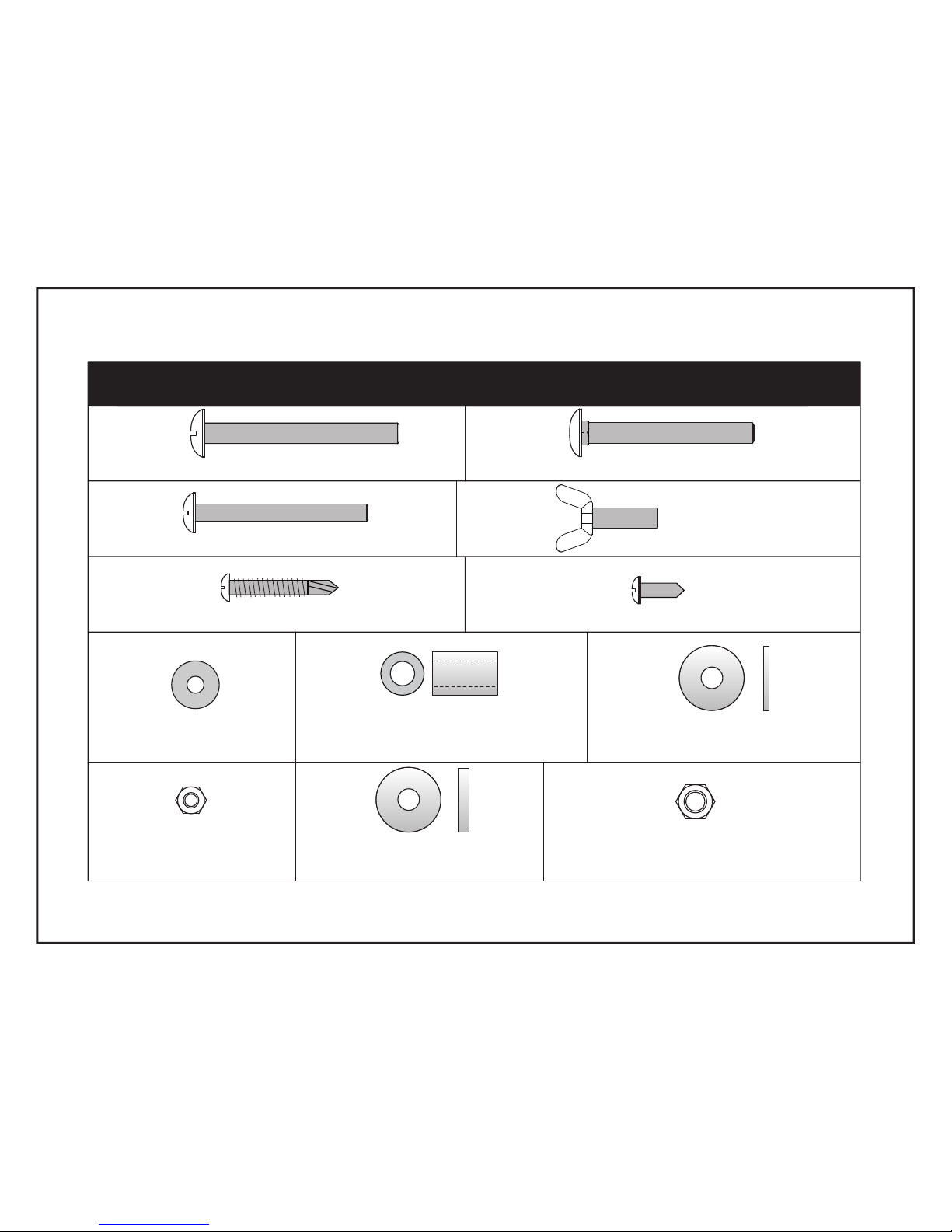
1/2 OD X .281 ID X 3/4 Long
Plastic Spacer (4 pieces)
13
3/4 OD X1/4 ID X 1/16 Thick Flat
Plastic Washer (4 pieces)
#10-24 Locknut (4 pieces)
#10 Washer (8 pieces)
HARDWARE IDENTIFICATION
12
1/4-20 Locknut (8 pieces)
1/4-20 X 2 1/4 Phillips Rd. Hd. Bolt (4 pieces)
#10-24 X 2" Phillips Rd. Hd. Bolt (4 pieces)
1/4-20 X 2 Carriage Bolt (4 pieces)
10
#8-32 X 1 1/4 Phillips Rd. Hd. Sms (8 pieces)
16
#8 X 1/2 Phillips Rd. Hd. Sms (100 pieces)
15
2
33
#10-24 X 3/4 Thumb
Screw (4 pieces)
3/4 OD X1/4 ID X 1/8 Thick Flat
Plastic Washer (4 pieces)
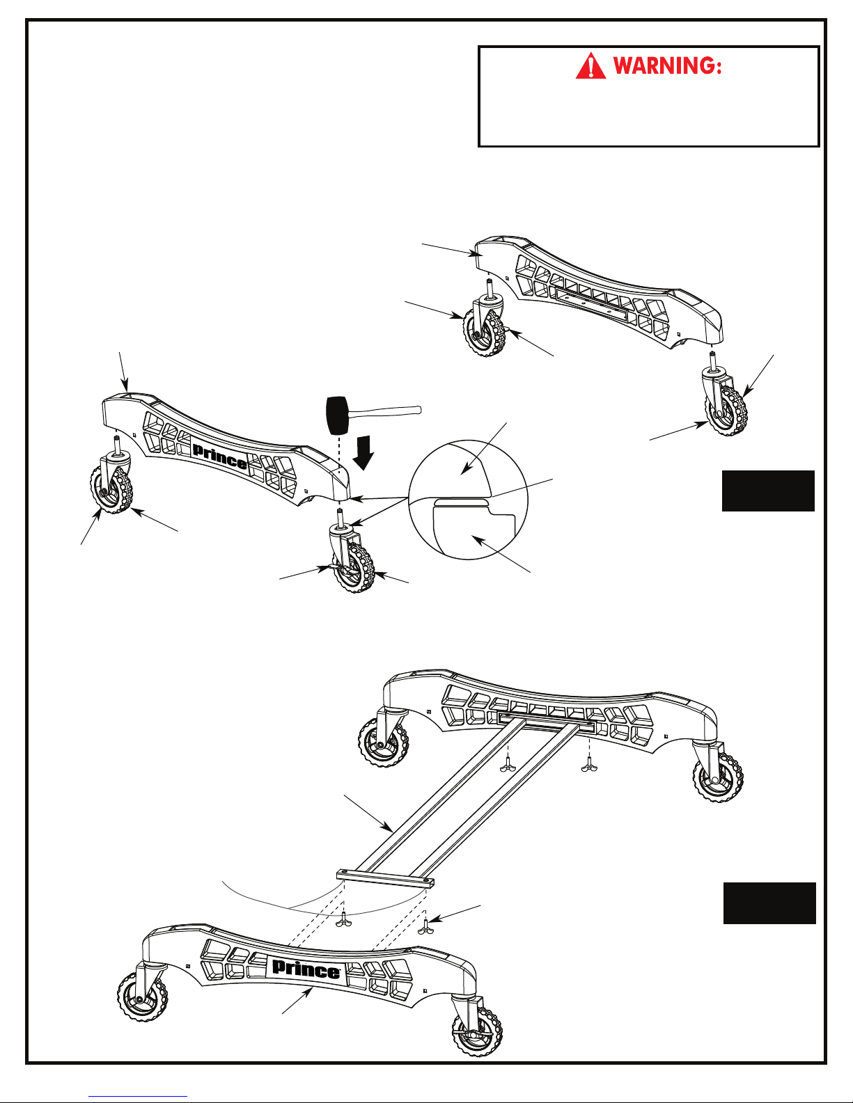
NOTE: If casters came pre-assembled
on Caster Beam (#8), skip to Step 2.
1. Slide a Caster Wheel with Lock (#30) into Caster Beam
as shown in FIGURE 1. On the other end of the Caster
Beam attach a Caster Wheel without Lock (#9).
Make sure you have one Caster Wheel with lock and a
Caster Wheel without lock for each Caster Beam.
Repeat this step to attach the Casters to the second
Caster Beam.
Parts Needed:
8
2 pcs - #8 Caster Beam
2 pcs - #9 Caster without lock
2 pcs - #30 Caster with lock
8
30
Rubber Hammer
without lock
9
with lock
9
30
READ AND FOLLOW ALL ASSEMBLY, OPERATING,
fAND SAFETY INSTRUCTIONS CAREFULLY. AT LEAST
TWO (2) ADULTS ARE NEEDED TO PUT THIS TABLE
TOGETHER!
without
with lock
8
9
NOTE:
Make sure the Caster
Stem is completely installed
into Caster Beam as shown.
30
lock
Figure 1
2. Attach Cross Tube (#7) to Caster Beam Assemblies (#8) using four Thumb Screws (#28) as shown
in FIGURE 2. Tighten bolts snug but DO NOT over tighten.
Parts Needed:
1 pc - #7 Cross Tube
Hardware Needed:
4 pcs - #28 #10-24 Thumb Screw
7
NOTE: Assemble with
threaded insert facing down.
28
8
Figure 2
3
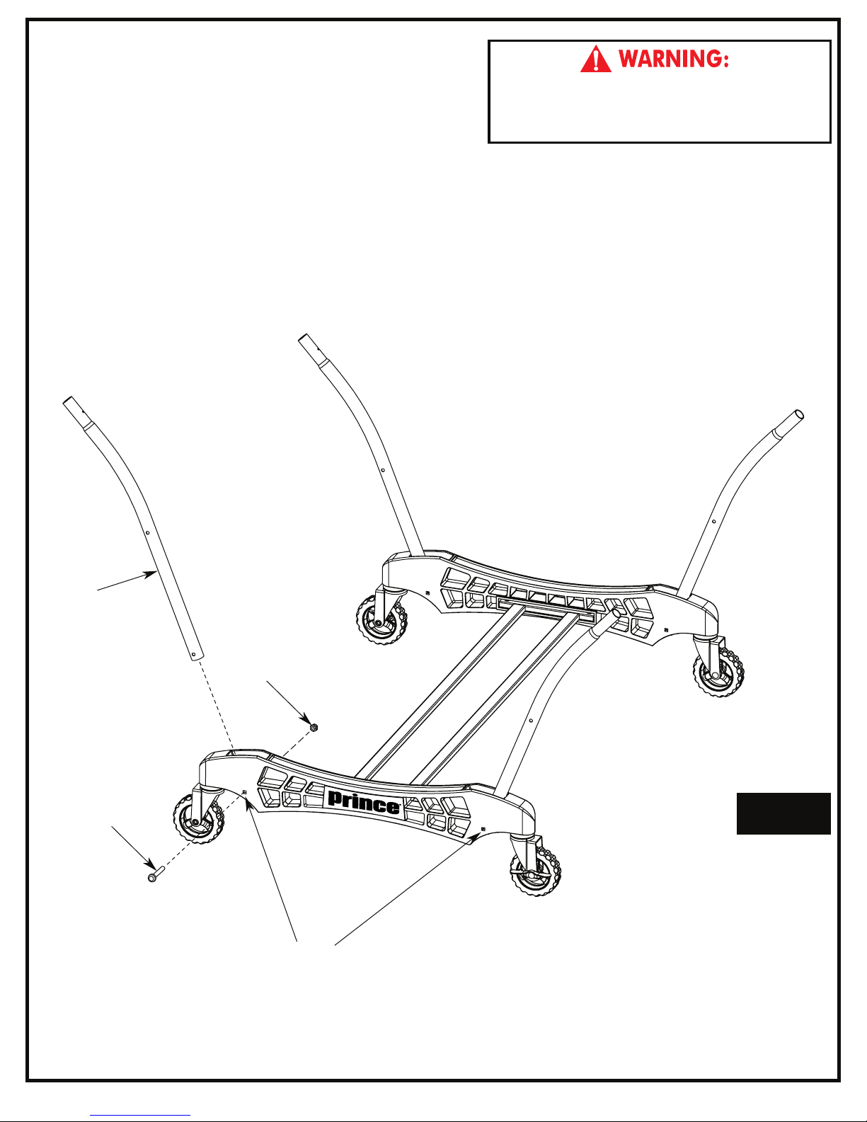
3. Attach four Strut Tubes (#4) to Caster Beam Assembly
with four Carriage Bolts (#10) and four Locknuts (#14)
as shown in FIGURE 3. Tighten nuts snug but DO NOT
over tighten.
Hardware Needed:
4 pcs - #10 Carriage Bolt
4 pcs - #14 Locknut
Parts Needed:
4 pcs - #4 Strut Tube
READ AND FOLLOW ALL ASSEMBLY, OPERATING,
AND SAFETY INSTRUCTIONS CAREFULLY. AT LEAST
TWO (2) ADULTS ARE NEEDED TO PUT THIS TABLE
TOGETHER!
4
14
10
Figure 3
NOTE:
Snug, but DO NOT over-tighten these four pivot points.
4
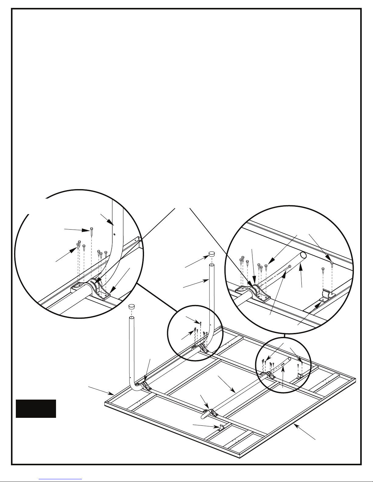
4. A) Attach two 1" Plastic Clips (#23) to bottom of aluminum top assembly using four Screws (#15) as
shown in FIGURE 4 and DETAIL B.
B) Attach U-Leg (#1) with two 1-1/2" Plastic Tube Brackets (#27) as shown in FIGURE 4 and
DETAIL A. Attach with twelve Screws (#15). CAUTION: Slots in Plastic Tube Brackets (#27)
must face toward middle of table exactly as shown or the table will not operate properly.
C) Attach U-Support (#3) with two 1" Plastic Tube Brackets (#24) as shown in DETAIL B. Attach with
twelve Screws (#15). CAUTION: slots in Plastic Tube Brackets (#24) must face toward middle
of table exactly as shown or the table will not operate properly.
D) Rotate U-Leg (#1) and U-Support (#3) until you see the screw hole in the slot of Tube Bracket (#27)
and (#24). Slide U-Leg and U-Support side to side if necessary to see hole. See DETAIL A & B.
E) Thread two Screws (#16) through slot in Plastic Tube brackets (#24) & into U-Support (#3) and two
Screws (#16) through slot in Plastic Tube Brackets (#27) & into U-Leg (#1) as shown in DETAIL A & B.
F) Slide two Plastic Leg Caps (#20) onto ends of U-Leg (#1).
Hardware Needed:
28 pcs - #15 Phillips Rd. Hd. Screw
4 pcs - #16 Phillips Rd. Hd. Screw
DET
AIL A
Tube Bracket Slots
Parts Needed:
1 pc - #1 U-Leg-White
1 pc - #2 Aluminum Top Assembly
1 pc - #3 U-Support-White
2 pcs - #20 Plastic Leg Cap
2 pcs - #23 1” Plastic Clip
2 pcs - #24 1’’ Plastic Tube Bracket
2 pcs - #27 1-1/2” Plastic Tube Bracket
1
DET
16
AIL B
15
15
NOTE: Tighten screws snug,
but do not overtighten, causing
screws to strip in metal tube.
2
Figure 4
27
27
15
20
1
16
24
24
3
16
23
15
3
16
NOTE: All Tube Bracket Slots face toward
middle of the table. As shown in Figure 4.
23
Middle of table is
end without stripe.
5
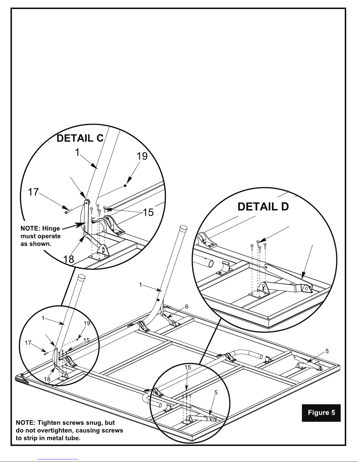
5. A) Attach one LH short Hinge & Mounting Bracket Assembly (#18) using four Screws (#15) as shown in
DETAIL C. Attach one RH short Hinge & Mounting Bracket Assembly (#6) using four Screws (#15) as
shown in FIGURE 5. Attach two Long Hinge & Mounting Bracket Assemblies (#5) using eight Screws
(#15) as shown in DETAIL D & FIGURE 5.
B) Attach LH short Hinge & Mounting Bracket Assembly (#18) and RH short Hinge & Mounting Bracket
Assembly (#6) to U-Leg (#1) using two Bolts (#17) with two Thick Flat Plastic Washers (#33) and two
Locknuts (#19) as shown in FIGURE 5 and DETAIL C. DO NOT OVERTIGHTEN hinge must pivot.
Note: 1/8” Thick Plastic Washer (#33) goes between Hinge and Leg.
REPEAT STEPS 4-5 ON THE OTHER ALUMINUM TOP ASSEMBLY.
CAUTION: Hinges must be positioned
exactly as shown or table will not operate
correctly and could be damaged.
Do not overtighten nuts, hinge must pivot.
33
(Thick Washer)
Parts Needed:
1 pc - #6 RH short Hinge & Mounting Bracket Assembly
1 pc - #18 LH short Hinge & Mounting Bracket Assembly
2 pcs - #5 Long Hinge & Mounting Bracket Assembly
Hardware Needed:
16 pcs - #15 Phillips Rd. Hd. Screw
2 pcs - #17 Phillips Rd. Hd. Bolt
2 pcs - #19 Locknut
2 pcs - #33 Flat Plastic Washer (1/8” Thick)
33
15
5
6

6. Attach table top to base assembly. Pivot Strut Tubes (#4)
up and then with at least one adult on each side of table
top, lift top and align ends of U-support Tube (#3) with
tops of strut tubes on caster beams as shown in
FIGURE 6.
Slide tubes together. Repeat for other Table Top.
3
AT LEAST TWO (2) ADULTS ARE NEEDED T O
COMPLETE THE REST OF THIS ASSEMBLY! WHEN
ASSEMBLING TOPS TO BASE, HANDLE TOP
ASSEMBLIES BY GRASPING ONLY THE T OPS
THEMSELVES. DO NOT GRASP METAL LEGS, USUPPORT, LINKAGE, OR HINGES. THESE PARTS
CAN MOVE AND COULD PINCH FINGERS OR
HANDS CAUSING SERIOUS INJURY! ASSEMBLE
AS SHOWN WITH LEGS FULLY CLOSED AND
TOPS IN A VERTICAL POSITION. DO NOT OPEN
LEGS AND TRY TO ASSEMBLE. TABLE TOPS ARE
HEAVY - DO NO T ATT EMPT TO ASSEM BLE
ALONE!
DO NOT OPEN THE TABLE TO PLAYING POSITION
UNTIL BOTH TOPS ARE INSTALLED! DO NOT LEAVE
TABLE STANDING UNATTENDED. IT C OULD BE
KNOCKED OVER CAUSING SERIOUS BODILY INJURY
OR PROPERTY DAMAGE.
Figure 6
4
NOTE: PIVOT STRUT TUBES UP AS SHOWN.
7
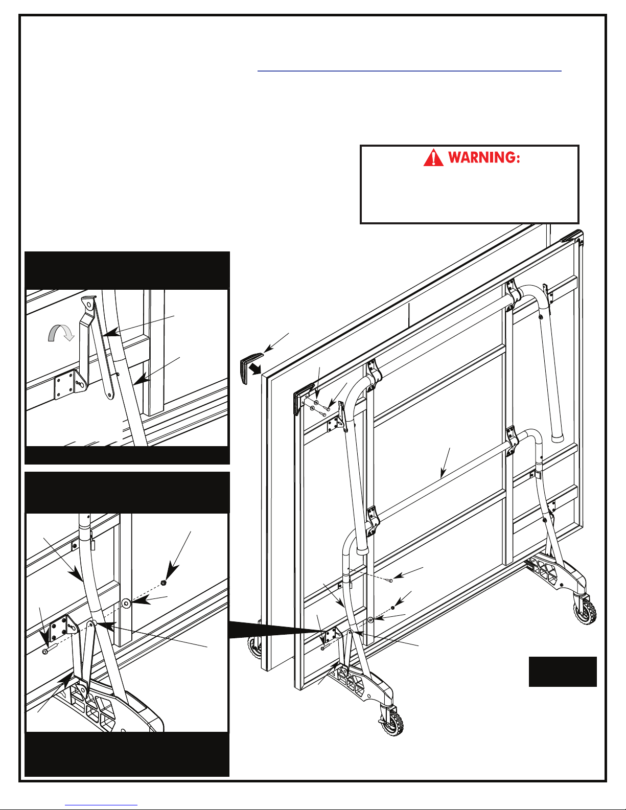
7. Attach U-Support (#3) and Strut Tubes (#4) using two Screws (#15) as shown in FIGURE 7.
Note: If hinge (#5) is positioned as shown in DETAIL E, you will have to rotate the hinge to the position shown in
Detail F. DO NOT unscrew the hinge, you can rotate the hinge without unscrewing it from the table. If you want to
see a video on how to position Hinge (#5) go to: http://www.escaladesports.com/customer-service/videos.html
8. Attach Long Hinge & Mounting Bracket Assemblies (#5) to Strut Tubes (#4) using two Bolts (#12), two Spacers (#11),
two Flat Plastic Washers (#13) and two LockNuts (#14) as shown in FIGURE 7 and DETAIL F.
Tighten Nuts snug, but DO NOT OVERTIGHTEN, hinges must pivot.
9. Attach two Corner Protectors (#25) to Top Assembly using four Screws (#15) with four Washers (#26) as shown in FIGURE 7.
Repeat for other Table Top.
Hardware Needed:
2 pcs 2 pcs - #12 Phillips Rd. Hd. Bolt
2 pcs - #13 Flat Plastic Washer
2 pcs - #14 LockNut
6 pcs - #15 Phillips Rd. Hd. Screw
4 pcs - #26 Washer
#11 Spacer
ATTENTION: If hinge is positioned as shown
below (DETAIL E), rotate the hinge as shown in
DETAIL F. Do not take hinge off.
5
4
DET
AIL E
INCORRECT POSITION OF HINGE
Part Needed:
2
#25 Corner Protector
pcs -
DO NOT OPEN THE TABLE TO PLAYING POSITION
UNTIL BOTH TOPS ARE INSTALLED! DO NOT LEAVE
TABLE STANDING UN ATTEN DED. IT COUL D BE
KNOCKED OVER CAUSING SERIOUS BODILY INJURY
OR PROPERTY DAMAGE.
25
26
15
3
CAUTION: Position hinges exactly as
shown in DETAIL F or table will not
operate correctly and could be damaged.
14
4
12
DET
13
AIL F
1
1
5
CORRECT POSITION OF HINGE
In the correct position Hinge (
like a “V” when attached to Strut Tube (#4).
#5) will look
12
5
15
4
14
13
11
Figure 7
NOTE: Tighten screws snug,
but do not overtighten, causing
screws to strip in metal tube.
8
 Loading...