

Page 1
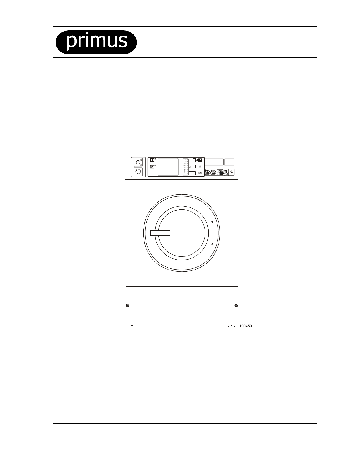
FS 6-16
INSTALLATION AND MAINTENANCE MANUAL SOFT MOUNTED WASHER EXTRACTOR
PUBLICATION DATE : Sep 05 WITH ELECTRONIC PROGRAMMER
100646
Page 2
100646 PUBLICATION DATE Sep 05 INSTALLATION AND MAINTENANCE MANUAL 1
1. TABLE OF CONTENTS
Publication dat e : Sep 05
1. TABLE OF CONTENTS................................................................................................1
2. WARNINGS...................................................................................................................2
3. TECHNICAL INFORMATION........................................................................................3
4. MACHINE INSTALLATION...........................................................................................7
4.1. MACHINE INSPECTION.....................................................................................................................7
4.2. MACHINE STORAGE.........................................................................................................................7
4.3. MACHINE POSITIONING...................................................................................................................7
4.3.1. FRE EL Y ON THE FLOOR............................................................................................................8
4.3.2. FRE EL Y ON AN ELEVATION......................................................................................................8
4.3.3. FIX E D ON AN EL E VATION..........................................................................................................9
4.3.4. LEVELING THE MACHINE........................................................................................................ 10
4.4. SHIPPING BARS..............................................................................................................................10
4.5. ELECTRICAL CONNECTION ........................................................................................................... 12
4.5.1. GEN ER A L................................................................................................................. .................12
4.5.2. EMERGENCY STOP DEVICE....................................................................................................12
4.5.3. SUPPLY CABLE AND SAFETY DEVICES.................................................................................12
4.5.4. INS T A L L SUPP L Y CABLE TO THE MAC H IN E..........................................................................13
4.5.5. CHECKING ROTATION DIRECTION.........................................................................................14
4.5.6. MULTIPLE MACHINES IN LINE SIMPLE PHASE ......................................................................14
4.6. CONNECTION OF WATER SUPPLIES............................................................................................14
4.7. CONNECTION OF LIQUID WASHING SOAPS DOSING.................................................................. 17
4.8. PREPARING THE MACHINE FOR OPERATION..............................................................................18
5. MAINTENANCE AND ADJUSTMENTS......................................................................19
5.1. MAINTENANCE...............................................................................................................................19
5.2. ADJUSTMENTS AND PART´S EXCHANGES..................................................................................20
6. TROUBLESHOOTING AIDS.......................................................................................24
6.1. ERROR HANDLING .........................................................................................................................24
6.2. PROBLEM CHECK LIST..................................................................................................................24
6.3. DOOR FAILS TO OPEN...................................................................................................................26
7. LIST OF RECOMMENDED SPARE PARTS...............................................................27
8. PUTTING THE MACHINE OUT OF SERVICE ............................................................28
8.1. DISCONNECTING THE MACHINE................................................................................................... 28
8.2. MACHINE LIQUIDATION..................................................................................................................28
8.2.1. POSSIBILITY OF THE MACHINE LIQUIDATION BY THE SPECIALIZED COMPANY................28
8.2.2. POSSIBILITY OF THE MACHINE LIQUIDATION BY OWN POTENTIAL....................................28
Page 3
2 INSTALLATION AND MAINTENANCE MANUAL PUBLICATION DATE Sep 05 100646
2. WARNINGS
FAILURE TO COMPLY WITH THE INSTRUCTIONS IN THIS MANUAL MAY LEAD TO INCORRECT USE
OF THE WASHER EXTRACTOR, AND MAY RESULT IN BODILY INJURIES OR DEATH AND/OR
DAMAGE TO THE LAUNDRY AND/OR THE WASHER EXTRACTOR.
♦ This English version is th e ori gi n al ver s i on .
♦ This instruction is not complete without „User“, „Installation and Maintenance“, „Programming“, „Spare parts manual“.
♦ Bef ore inst alling, operating or maintaining the mac hi n e, r ead and f ollow these instr uc ti ons c arefully and keep t h em in a han d y place
for later use. Safety instr uc tions includ ed in man u als f or p ers on nel operating t h e wash ing machin e must be pri nted and posted
on a visible place near the machine in the laundry room.
♦ Follow all basic and valid safety instructions and laws. Do not bypass the instructions stated in the instruction manual and warnings
on the labels . The labels must st ay on th e mac hine and they mus t b e legi ble.
♦ Install at i on and s ervice can be don e onl y b y a s ervice organiz ati on w it h pr op er authorization.
Do not let children use, play in, on, or around the machine.
♦ Any chang es c oncerning the ins tallation wh ic h ar e not d esc ri bed in this Install at i on M anu al m us t be ap pr ov ed by the suppli er
or manuf act urer. Otherwise, the suppli er and m anufacturer ar e not res ponsible f or potential injur i es t o operators or for an y da mages.
Interven t i ons in th e m ach ine executi on or func tions are not allowed, and th e man ufacturer ref uses any respons ibility in such c ases.
♦ During transportat i on an d st orage never us e exc essive forc es on th e c art on box b ecause comp on ent s c an be d am ag ed protrudin g
the contour line of the machine.
♦ The wash er e xtractor must be ins t all ed on level. If not, the m ac hine may become unbalanc ed dur ing extracti on and , although fitted
with an unbalance saf ety, the machine may become seri ous l y d am aged what may res ul t in bodily injuri es.
♦ Never transport the machine without the transporting braces mounted.
♦ Never put t h e mac hi n e in op er at ion when the trans p or ti n g br aces are not remo ved .
♦ To prevent the possibil ity of electric al sh oc k, m ak e sur e the washer has been properl y grou nd ed i n accordance wit h th e installation
instruct i ons and AL L l oc al c od es.
Use copper c onduc t or s onl y. This appliance must be conn ect ed to a supply circu it to which no lighting units or general-purp os e
recept acl es ar e c onn ec t ed.
♦ The machine must be connected to the power, ground, water, ventilation and steam supply according to the Installation manual,
in compliance with the local standards done by qualified technicians with proper authorization. The valid standards for connecting
to the local power network (TT / TN / IT, ...) must be followed. In the standard execution, the washer may not be suitable for connecting
to an IT suppl y s yst em .
♦ All machines types are produced according the EMC-directive (Electro-Magnetic-Compatibility). They can be used in restricted
surroundings only (comply minimally with class A requirements). For safety reasons there must be kept the necessary precaution
distances with sensitive electric al or electronic d evice(s).
♦ If you have a machine with frequency inverter do not change the parameters of the inverter. Doing so can cause serious injury, fire,
machine damage, etc.
♦ Before removing top or back panel of the machine, switch power off and wait for at least 10 minutes. Before starting inspection of frequency
inverter, check for residual voltage across main circuit terminals + and -. This voltage must be below 30 VDC before you can access
the inverter for inspection.
♦ The washer extractor is intended to be permanently connected to fixed wiring.
♦ The washer must not be operated when the finger protection rubbers are removed or damaged.
♦ Do not exp os e the washing extractor to exc ess i v e humidity or ext r eme temperat ur es.
♦ Keep th e top of th e machine clean , without the presence of flamm able materials . Do n ot w as h or s pray the machin e wi th running water.
♦ Do not oper ate the washer ext ractor when part s ar e br ok en or missing or when c overs are open. The mach in e m ay not operat e until
the fixed guards are put correctly in place.
♦ Do not tam p er wit h t h e w ash er ext ractor contr ols an d do not bypass the s af et y instructions an d the warnings .
♦ Do not stor e flammable mat eri als around the mach in e.
♦ Defin e the d angerous areas in t h e laun dry room and obstruct an admiss i on t o th em duri ng machine's operating.
♦ Carefully read and follow the instructions on the packaging of detergents. Observe all warnings, cautions and labels to avoid personal
injury. Store deterg ents , lau ndry aids and dis infectants out of reach of children , pr eferably in a lock ed c abi n et.
Do not put articles soiled with explosive solvents and/or dangerous chemical products in the machine for any reason.
Do not open door until cylinder remains stopped and water has been drained from cylinder.
♦ Always dis connect the p ower su pp l y and cl os e all w at er an d st eam val ves while servic i ng the washer extractor.
♦ Although the washer may be in the „off“ position, there is still electric al power to the switch supply terminals.
Do not repair or adjust belt drive when the machine is in operation. Do not repair or replace any part of the washer, or attempt any servicing
unless specifically recommended in the maintenance instructions.
Original or identical parts must be used for replacement in this washer extractor. After servicing replace and secure all panels
in the original way. Take these measures for continued protection against electrical shock, injury, fire and/or property damage.
♦ If steam is leaking, turn off the main steam supply and contact the maintenance worker.
♦ Turn off the mai n supply like wat er , st eam , el ec tr ic i t y at the en d of eac h operating day.
♦ Check the functionin g of t h e door l oc k m ech anism on regul ar base.
♦ Regul arl y once a three months check the pr op er func t i on of gr ou nd and emergency button.
♦ The emergency stop device is omitted on machines design for coin, token, external payment system or similar operation for use
in self-service situation. The owner-installer-user must provide a remote-located emergency stop device that is connected to each machine .
♦ Under certain conditions, hydrogen gas may be created in the hot water system that has not been used for two or more weeks.
Hydrogen gas is explosive. If the hot water s ys t em h as n ot been used for such p er i od op en all h ot water taps and let th e water run out
for few min ut es. T h is wi ll rel ease any accum ulated gas. As this gas is flammabl e, d o not s m ok e or use open flames during this time.
♦ The instructions and wa rnings described in this manual do not include all conditions and situations which may occur during the installation,
maintain or operate of your machine. They must be generally understood. Caution and care are factors which are not included in the de sign
of this machine and all persons who install, operate or maintain the machine must be qualified and familiar with the operating instructions.
♦ If any prob l ems or f ailures occur which you do not unde rs t a n d, im m ed iately contac t you r d ealer, servic em an or man ufacturer.
= Warnings and labels present on the machine
Page 4
100646 PUBLICATION DATE Sep 05 INSTALLATION AND MAINTENANCE MANUAL 3
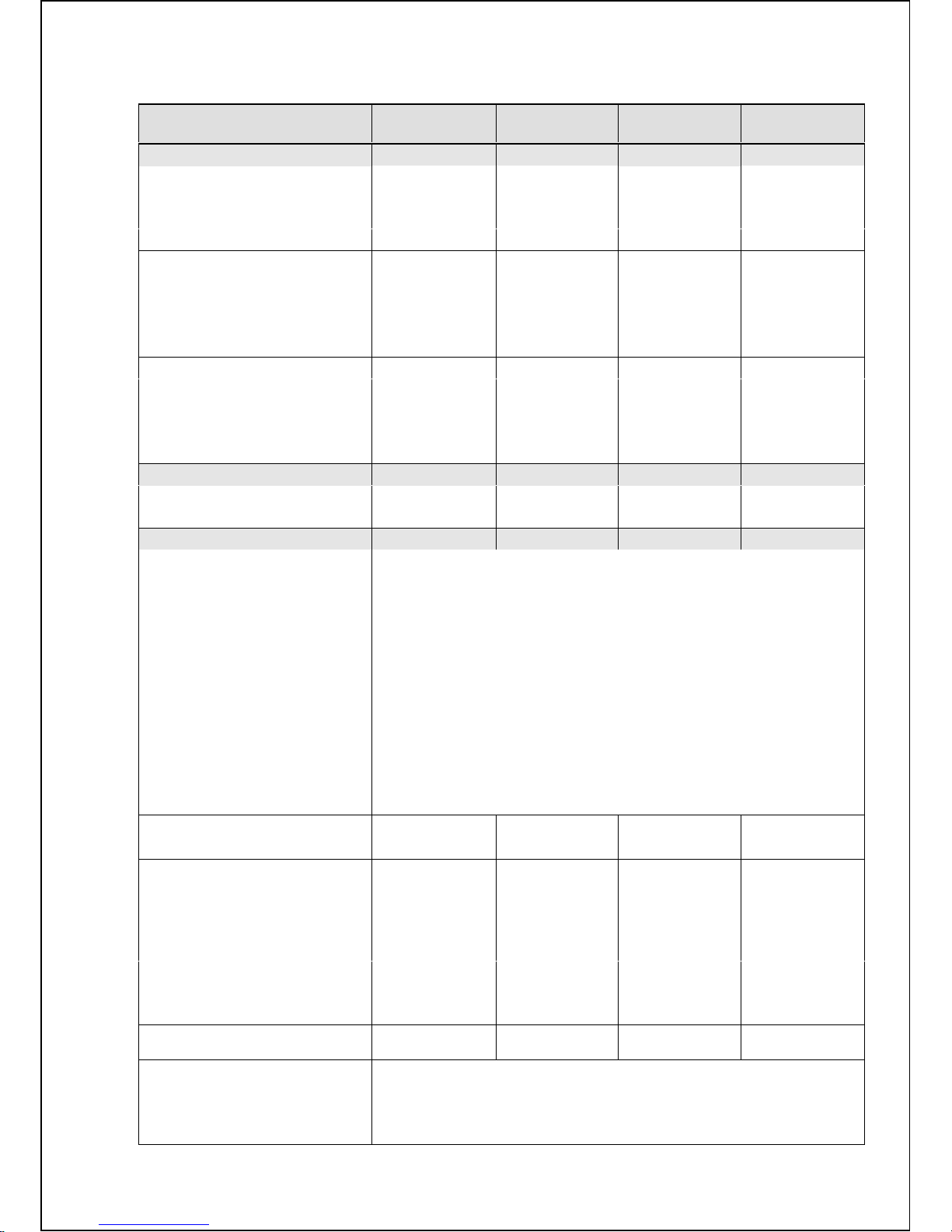
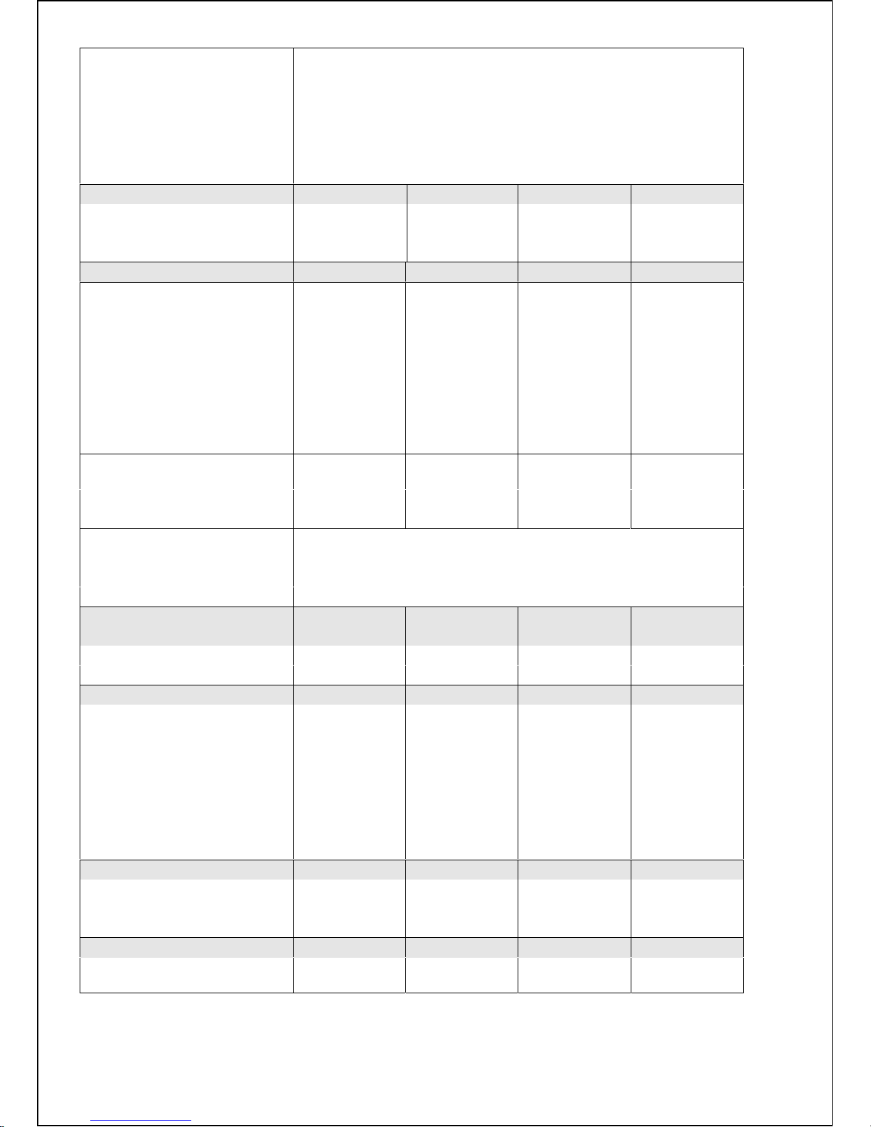
3. TECHNICAL INFORMATION
LOAD CAPACITY OF DRY
LINEN (1/10)
6 kg / 13 lb 7 kg / 16 lb 10 kg / 22 lb 16 kg / 36 lb
DIMENSIONS
MACHINE DIMENSIONS
Width 660 mm/25.98“ 660 mm/25.98“ 660 mm/25.98“ 835 mm/32.87“
Depth 770 mm/30.31“ 770 mm/30.31“ 865 mm/34.05“ 1040 mm/40.94“
Height 1070mm/42.12“ 1070mm/42.12“ 1130mm/44.48“ 1295 mm/50.98“
PACKING DIMENSIONS
Width 750 mm/29.53“ 750 mm/29.53“ 750 mm/29.53“ 930 mm/36.61“
Depth 850 mm/33.46“ 850 mm/33.46“ 950 mm/37.40“ 1140 mm/44.88“
Height 1250mm/49.21“ 1250mm/49.21“ 1300mm/51.18“ 1510 mm/59.44“
Transportation volume 0.79m3/27.89ft30.79m3/27.89ft30.92m3/32.48 ft31.6 m3/56.5 ft
3
DIMENSIONS OF INNER DRUM
Diameter 530 mm/20.86“ 530 mm/20.86“ 530 mm/20.86“ 650 mm/25.6“
Depth 270 mm/10,63“ 330 mm/12,99“ 420 mm/16.53“ 500 mm/19.68“
Drum Volume 60dm3/15.85gal 73dm3/19.28gal 95dm3/25.1gal 166dm³/43.8gal
Door opening 285 mm / 11,22“ 285 mm / 11,22“ 285 mm / 11,22“ 410 mm / 16,14“
WEIGHT
Net 230 kg / 508 lb 235 kg / 519 lb 275 kg / 607 lb 465 kg / 1026 lb
Gross 240 kg / 530 lb 250 kg / 552 lb 300 kg / 662 lb 495 kg / 1092 lb
ELECTRICAL DAT A
3x380-415V+N 50Hz - applicable for 16 kg / 36 lb
3x380-415V 50Hz - applicable for 16 kg / 36 lb
3x380V 60Hz - applicable for two motor drive
3x440-480V 60Hz
3x220-240V 50Hz
3x200V 50/60Hz
3x208-240V 60Hz
3x380-415V+N 50/60Hz -
applicable for electrical heating
1x220-240V 50/60Hz - not app licable for elec trical heating
3x220-240V 50/60Hz - applicable for electrical heating
1x200-208V 50/60Hz - applicable for 10 kg / 22 lb, 16 kg / 36 lb,
not applicable for electrical heating
3x200-208V 50/60Hz - applicable for 10 kg / 22 lb, 16 kg / 36 lb,
applicable for electrical heating
3x380-480V 50/60Hz
Permitted deviation of voltage - 6% to +10% V -6% to +10% V -6% to +10% V -6% to +10% V
Permitted deviation of frequency
±1% Hz ±1% Hz ±1% Hz ±1% Hz
TOTAL INPUT OF THE
MACHINE WITH
Electric heating 6kW 6.75 kW 6.75 kW 7. 5 kW Electric heating 9 kW
9.75 kW 9.75 kW 10.5 kW 11. 3kW
Electric heating 12 kW - 12.75 kW 13.5 kW 14.3kW
Electric heating 18 kW - - - 20.3kW
Without heating or steam 0.75 kW 0.75 kW 1. 5 kW 2.3kW
Nominal output of motor 0.75 kW 0.75 kW 1. 5 kW 2.2kW
NOMINAL OUTPUT OF THE MOTOR
AT RPM
0.75 kW 0.75 kW 1. 5 kW 2.2kW
INPUT PROTECTION
Electric heating 6kW (220-240V)
25A
Electric heating 6kW (400/440V 3AC)
16A
Electric heating 9kW (220-240V)
32A
*
Page 5
4 INSTALLATION AND MAINTENANCE MANUAL PUBLICATION DATE Sep 05 100646
Electric heating 9kW (400/440V 3AC)
20A
Electric heating 12kW (220-240V )
40A
Electric heating 12kW (400/440V 3AC)
25A
Electric heating 18kW (220-240V )
60A
Electric heating 18kW (400V 3AC )
40A
Electric heating 18kW (440V 3AC )
32A
Without el. heating (220-240C 1/3AC)
16A
WASHING FUNCTIONS
Washing 48 RPM 48 RPM 48 RPM 45 RPM
High extracting 1000 RPM 1000 RPM 1000 RPM 980 RPM
G-factor
300 300 300
350
CONNECTION
WATER CONNECTION
Water pressure
0.1-0.8 MPa /
1-8 bar /
14.5-116 PSI
0.1-0.8 MPa /
1-8 bar /
14.5-116 PSI
0.1-0.8 MPa /
1-8 bar /
14.5-116 PSI
0.1-0.8 MPa /
1-8 bar /
14.5-116 PSI
Recommended water pressure
0.3-0.5 MPa /
3-5 bar / 36.3 PSI
0.3-0.5 MPa /
3-5 bar / 36.3 PSI
0.3-0.5 MPa /
3-5 bar / 36.3 PSI
0.3-0.5 MPa /
3-5 bar / 36.3 PSI
Water in let G3/4" G3/4" G3/4" G3/4"
Maximal water temperature
90°C / 194°F 90°C / 194°F 90°C / 194°F 90°C / 194°F
CONNECTION OF WATER
DRAINAGE
Via drain valve diameter
76 mm/3" 76 mm/3" 76 mm/3" 76 mm/3"
Flow amount with drain v alv e 3.5 l/s 3.5 l/s 3.5 l/s 3.5 l/s
CONNECTION OF STEAM
Steam connection G1/2“
Steam pressure low 1-3 bar / 14,5 - 44 PSI
Steam pressure high 3-8 bar / 44-116 P SI
ELECTRICAL CONSUMPTIO N
Light soiled fabrics, wash 60°C(1)
Without elect ri cal heating 0.2 kWh 0.2 kWh 0.3 kWh 0.5kWh
With electric al heating 1.2 kWh 1.3 kW 1.7 kW 3.5kWh
WORKING CONDITIONS
Ambient temperature +5°C (41°F) to
+35°C (95°F)
+5°C (41°F) to
+35°C (95°F)
+5°C (41°F) to
+35°C (95°F)
+5°C (41°F) to
+35°C (95°F)
Relative humidity
30% to 90%
without
condensation
30% to 90%
without
condensation
30% to 90%
without
condensation
30% to 90%
without
condensation
Heigth abov e sea level
up to 1000 m /
3280 ft
up to 1000 m /
3280 ft
up to 1000 m /
3280 ft
up to 1000 m /
3280 ft
Storage temperature 0°C (32°F) to
+55°C (131°F)
0°C (32°F) to
+55°C (131°F)
0°C (32°F) to
+55°C (131°F)
0°C (32°F) to
+55°C (131°F)
BOTTOM LOAD
Max.stati c load on floor 2413 N 2492 N 3002 N 5450N
Max.dynamic load on fl oor 650 N 730 N 1100 N 1220 N
Frequency of dynami c l oad 16 Hz 16 Hz 16 Hz 16Hz
NOISE
Equivalent sound power l evel
Leq (dB(A))
< 70 dB(A) < 70 dB(A) < 70 dB(A) < 70 dB(A)
maximum dimensions including prot r uding parts
(1) Depends of temper ature of cold and hot water supply
*
Page 6
100646 PUBLICATION DATE Sep 05 INSTALLATION AND MAINTENANCE MANUAL 5
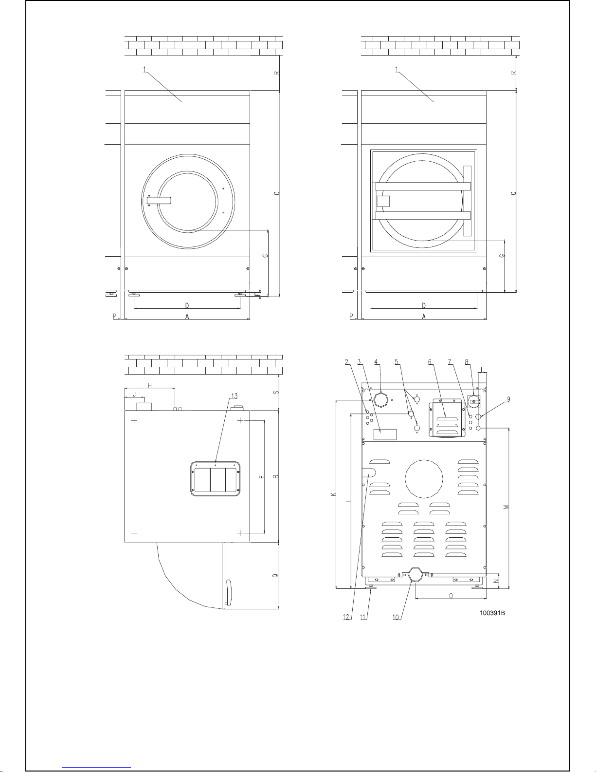
6kg / 13lb, 7kg / 16lb, 10kg / 22lb 16kg / 36lb machine with frequency control drive
Fig. 3.1.
1. Control panel
2. Connection liquid soap
3. Serial plate
4. Soap hopper venting
5. Water supply
6. Frequency inverter
7. Fuses
8. Main switch
9. Electrical supply connection
10. Drain
11. Adjustabl e leg
12. Steam connection
13. Soap hopper
Page 7
6 INSTALLATION AND MAINTENANCE MANUAL PUBLICATION DATE Sep 05 100646
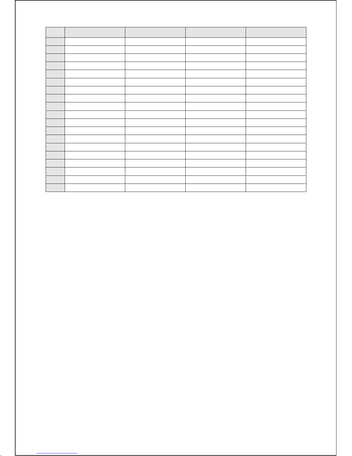
6kg / 13lb 7kg / 16lb 10kg / 22lb 16kg / 36lb
A
660 mm / 25.98“ 660 mm / 25.98“ 660 mm / 25.98“ 835 mm / 32.87“
B
685 mm / 26.97“ 685 mm / 26.97“ 785 mm / 30.91“ 960 mm / 37.8“
C
1070 mm / 42.13“ 1070 mm / 42.13“ 1130 mm / 44.49“ 1295 mm / 50.98“
D
560 mm / 22.05“ 560 mm / 22.05“ 560 mm / 22.05“ 715 mm / 28.15“
E
585 mm / 23.03“ 585 mm / 23.03“ 685 mm / 26.97“ 815 mm / 32.09“
F
20 mm / 0.79“ 20 mm / 0.79“ 20 m m / 0.79“ -
G
420 mm / 15.54“ 420 mm / 15.54“ 480 mm / 18.90“ 430 mm / 16.92“
H
263 mm / 10.35“ 263 mm / 10.35“ 263 mm / 10.35“ 300 mm / 11.81“
I
910 mm / 35.83“ 910 mm / 35.83“ 970 mm / 38.19“ 1135 mm / 44.68“
J
103 mm / 4.06“ 103 mm / 4.06“ 103 mm / 4.06“ 120 mm / 4.72“
K
980 mm / 38.58“ 980 mm / 38.58“ 1040 mm / 40.94“ 1195 mm / 47“
L
44 mm / 1.73“ 44 mm / 1.73“ 44 m m / 1.73“ 44 mm / 1.73“
M
835 mm / 32.87“ 835 mm / 32.87“ 895 mm / 35.24“ 1015 mm / 39.96“
N
78 mm / 3.07“ 78 mm / 3.07“ 78 m m / 3.07“ 55 mm / 2.16“
O
375 mm / 14.76“ 375 mm / 14.76“ 375 mm / 14.76“ 415 mm / 16.33“
P
10 mm / 0.39“ 10 mm / 0.39“ 10 m m / 0.39“ 15 mm / 0.6“
Q
445 mm / 17.52“ 445 mm / 17.52“ 445 mm / 17.52“ 530 mm / 20.86“
R
700 mm / 27.56“ 700 mm / 27.56“ 700 mm / 27.56“ 700 mm / 27.55“
S
600 mm / 23.6“ 600 mm / 23.6“ 600 mm / 23.6“ 600 mm / 23.62“
Page 8
100646 PUBLICATION DATE Sep 05 INSTALLATION AND MAINTENANCE MANUAL 7
4. MACHINE INSTALLATION
4.1. MACHINE INSPECTION
When the machine is delivered, it is necessary to do a visual inspection for any damage that may have occurred
during transit. If the pac k age or pallet are damaged or signs of possible damage are evi dent, let the carrier
note the condition on the shipping papers before the shipping receipt is signed.
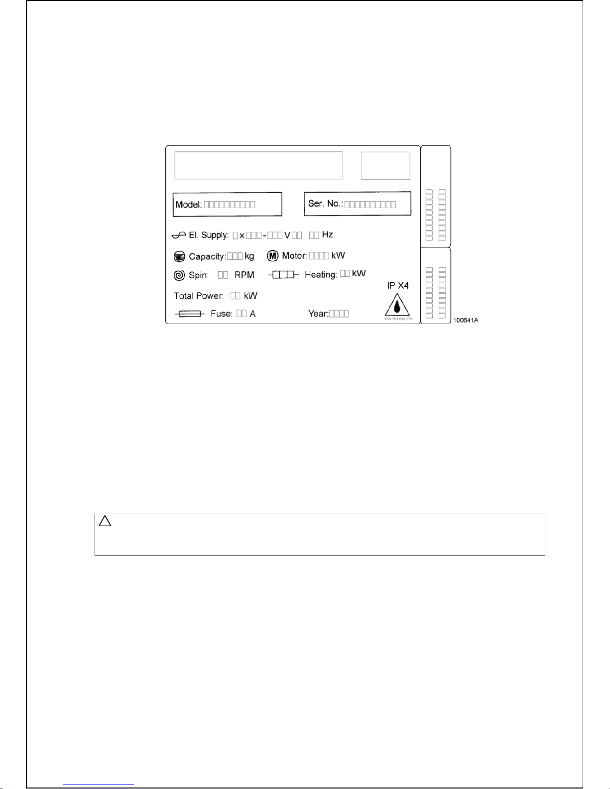
Remove the package as soon as possible and check if the information on the serial plate correspond with your
order. The serial plate is located on the rear of the machine, fig. 4.1. T his determines the type of model
you have bought, the v oltage and the serial number.
Fig. 4.1.Serial plate
Check if the machine is not dam aged and if all the accessories are included according to your order.
The accessories and manual s are located inside the machine.
4.2. MACHINE STORAGE
When the machine will be stored af ter delivery, be sure this is followed:
- Use the delivered package to protect the machine against moisture and di rt .
- The storage temperature is between 0°C / 32F and 55°C / 131F.
- The machine may not be installed within the reach of spraying water.
- Avoid severe climatic storage conditions and excessiv e humi dity. When the temperature changes and thi s
causes damp, you must av oi d water under and ar ound the machine and also on his covers.
- If possible, leave the machine in the transporting package or at least let it set on the transporting wooden
id until the time of final inst allation on the foundation accor ding the chapter 4.3. of this manual.
4.3. MACHINE POSITIONING
WARNING !
IF THE MACHINE IS LOCATED ON AN ELEVATED BASE FOR EASIER OPERATION, THE FRONT
LEGS OF THE MACHINE SHOULD BE SECURED FOR SAFETY REASONS.
- Before placing the m ac hi ne on its place, remove the packaging, loosen the rear panel ( see fi g. 4.4. pos.4)
and the service panel (see fi g. 4.4. pos.5). Remove the four bolts, which hol ds the m ac hine on the wooden
pallet. Lift up the mac hine carefully, take care not to damage the machine c om ponents.
- Leave at least a 0.6m / 23,6“ free space between the rear panel of machine and the wall. Leave at least
a 0.01 m / 0.39" free space between the side panel of the machine and the wall or other machine. Abov e
the machine must be minimum 0.7 m / 27.56“ of free space for the maintenance access.
- All passages and spaces the machine has to be transported through at install ation should be reasonably
dimensioned to meet t he height and width of the machine including the package.
- Never push, pull or press the com ponents protruding from the contour li ne of mac hi ne( c ontrol panel, door,
control elements, water inlet and outlet pipes, etc. ).
- Make sure that the filling door is closed during handling.
- Take ca r e that the f lo or where the mach ines will b e placed is underne a t h s upported. The wash e r s hould not be
installed on an upper floor or over a basement without approval of structural engineer about the requirements
of permissible l oading, vibrations and noise level in the building.
- Take care that the floor where the machines will be placed is not combustibl e.
!
Page 9
8 INSTALLATION AND MAINTENANCE MANUAL PUBLICATION DATE Sep 05 100646
4.3.1. FREELY ON THE FLOOR
The machine is to be located on a not elevated leveled concrete floor that com ply with static and dynamic
stress of the machi ne.
The friction coefficient must be higher then 0,5 between the rubber f eet and the floor material. Do not place
the machine on a smooth surf ace but on a rough floor material like concrete. If t he fri c tion coefficient is less,
then the machine can mo ve w hile s pinning. If this should happens fasten the machine, see „Fasten with an choring
bolts“.
MACHINES 6kg / 13lb, 7kg / 16lb, 10kg / 22lb
Position the machine only on his 4 adjustable rubber feet.
MACHINES 16kg / 36lb
Place between the four c or ners of the frame and the floor a thin rubber sheet of 10x10cm / 3.93“x 3.93“
with thickness between 1-2 / 0.04“-0.08“ maximum. We advice to fasten t his machines always, see „Fasten
with anchoring bolt s“.
4.3.2. FREELY ON AN ELEVATION
MACHINES 6kg / 13lb, 7kg / 16lb, 10kg / 22lb
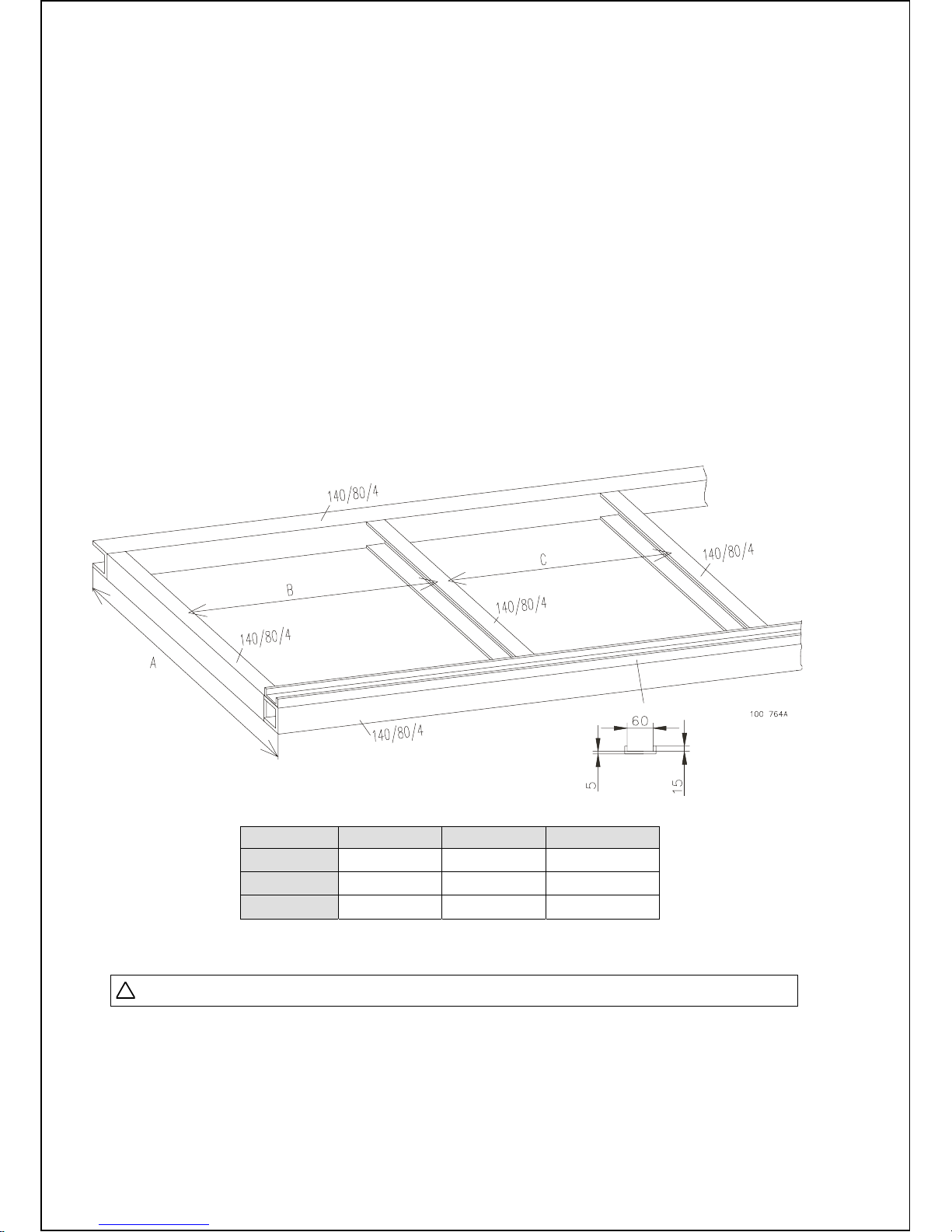
If you choose to place the machine on a m etal base or pad, use a U-profile to secure the machine positi on.
Fix the U-profile to the iron frame by welding or fix it to the floor by anchoring bolts. This is necessary to prevent
that the machine moves fr om the base. Mak e a base accor ding, fig. 4.3.2.
Place the machines front rubber feet in the U-profile.
Fig. 4.3.2. Design of metal base
6kg / 13lb 7kg / 16lb 10kg / 22lb
Distance A
660 660 760
Distance B
480 480 480
Distance C
590 590 590
Tab 4.3.2. Frame dimensi ons
WARNING ! NEVER DO THIS FOR A 16 kg / 36 lb MACHINE.
!
Page 10
100646 PUBLICATION DATE Sep 05 INSTALLATION AND MAINTENANCE MANUAL 9
4.3.3. FIXED ON AN ELEVATION
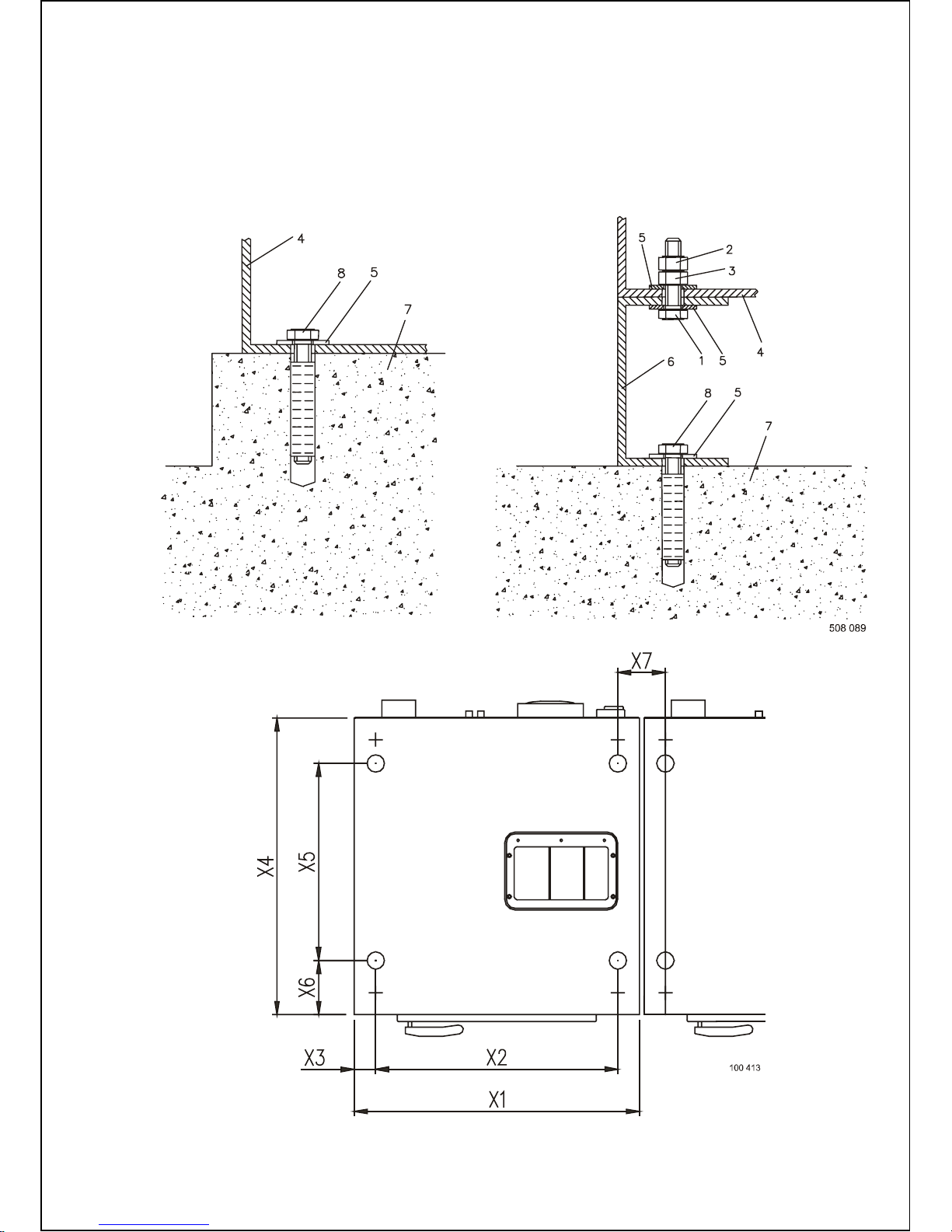
The machine can also be secured t o a m ounting base or foundation by means of bolts and anchoring bolt s
to assure the safety. When a c onc r ete pad or a fram e is used then is the maximum height 305 mm (12“).
The pad or frame must be designed so that it can carry the static and dynamic forces. The thick ness of ir on
profiles is minimum 4 mm (0.158“).
For 6kg / 13lb, 7kg / 16lb, 10kg / 22lb m ac hines, r em ov e the four rubber feeds from the machine frame.
Do not tighten anchoring bolts before the concrete base around the bol ts is completely secured.
Tighten the anchoring bolts with the prescribed torque of the bolts.
Fig. 4.3.3.A On an elevation
Fig. 4.3.3.B Frame fixation dimensions
1. Bolt M8
2. Securing nut
3. Nut M8
4. Machine frame
5. Washer
6. Elevation frame
7. Concrete floor
8. Anchoring bolt
Page 11
10 INSTALLATION AND MAINTENANCE MANUAL PUBLICATION DATE Sep 05 100646
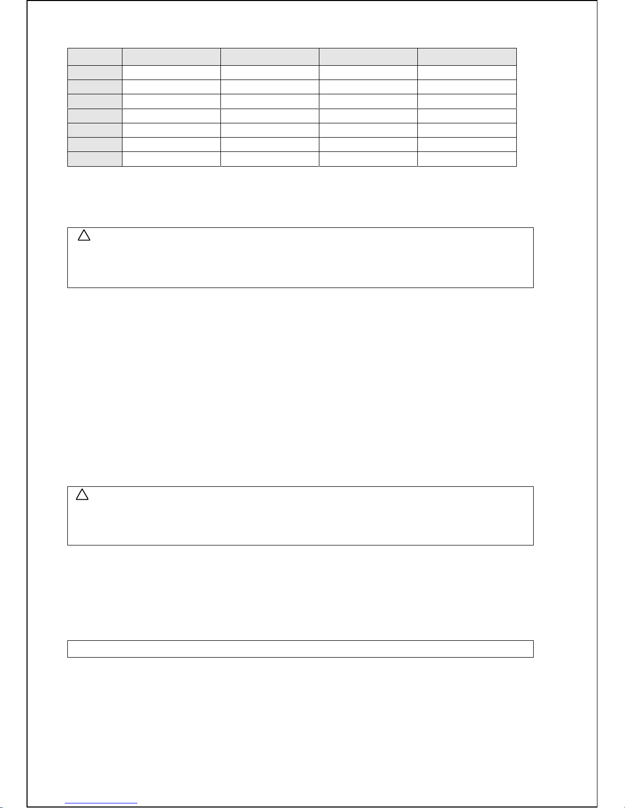
6kg / 13lb 7kg / 16lb 10kg / 22lb 16kg / 36lb
X1
660 mm / 25.98“ 660 mm / 25.98“ 660 mm / 25.98“ 830 mm / 32.7“
X2
560 mm / 22.05“ 560 mm / 22.05“ 560 mm / 22.05“ 715 mm / 28.1“
X3
50 mm / 1.97“ 50 mm / 1.97“ 50 mm / 1.97“ 57.5 mm / 2. 26“
X4
685 mm / 26.97“ 685 mm / 26.97“ 785 mm / 30.91“ 960 mm / 37.8“
X5
455 mm / 17.91“ 455 mm / 17.91“ 565 mm / 22.24“ 815 mm / 32.09“
X6
130 mm / 5.12“ 130 mm / 5.12“ 130 mm / 5.12“ 80 mm / 3.15“
X7
110 mm / 4.33“ 110 mm / 4.33“ 110 mm / 4.33“ 130 mm / 5.12“
Tab 4.3.3. Distanc es anchoring bolts
4.3.4. LEVELING THE MACHINE
WARNING !
THE MACHINE MUST RELIABLY REST IN ALL FOUR CORNERS OF THE MACHINE!
THE MACHINE MAY NOT ROCK.
THE MACHINE MUST BE IN WATER LEVELLED POSITION.
MACHINES 6kg / 13lb, 7kg / 16lb, 10kg / 22lb
The rubber feet are screwed on the bottom of the machine frame and are adjustabl e with a wrench siz e
13mm / 0.5" and 17mm / 0.7". Check the positi on of t he top of the m ac hine by a water level and adjust
machine legs, fig.3.1, pos.11. Adjust the four rubber feet until the machine is leveled and tighten the nuts
M10 back to the bottom of the fram e.
MACHINES 16kg / 36lb
The 16kg / 36lb machines don’t have rubber feet for adjustment to water level. When it is necessary use
thin hard plates of 10x 10cm / 3.93“x3.93“with thickness of 1mm / 0.04“ and plac e them under the f r am e
corner of the lowes t pos it ion. Use mo re of the m un t il the mac h ines stands water level. It is always advisab le
to bolt down this machi ne aft er leveling. Take care that the machine is in the lowest possible position.
If the machine with h is cab ine t rocks can it dama ge the machine cabinet. The manufacturer is not res ponsible
for consequences caused by a wrong i nstallation.
4.4. SHIPPING BARS
WARNING !
DO NOT TRY TO OPERATE THE MACHINE WITHOUT REMOVING THE SHIPPING BARS
DO NOT TRANSPORT THE MACHINE WITHOUT SHIPPING BARS MOUNTED.
OTHERWISE THIS CAN LEAD TO INJURY TO PEOPLE AND CAN DAMAGE THE MACHINE.
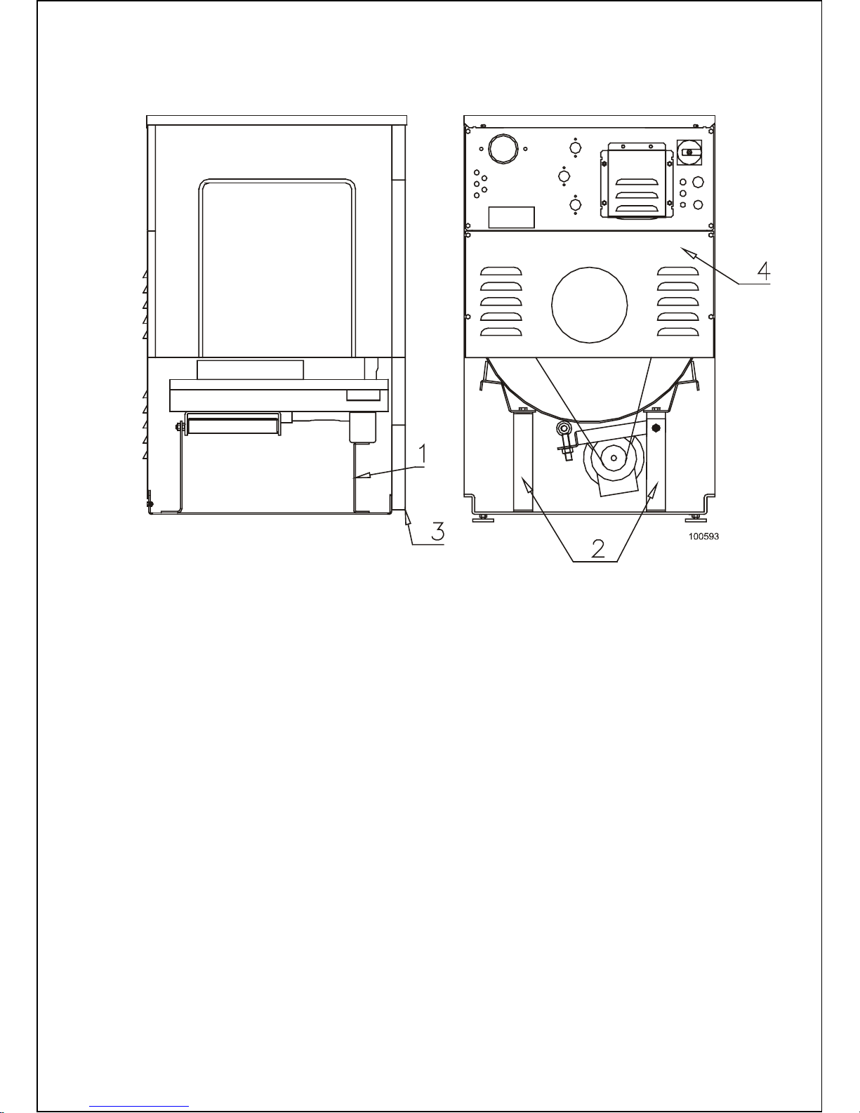
The machine is blocked f or transport. This eliminates all possibl e m ov em ent of the tub during transportation.
There are 3 striki ng shipping bars which must be removed before putting the mac hine i nto operation.
1. Remove fixation plate front, fig. 4.4. pos. 1.
2. Remove fixation plate rear right, fig. 4.4. pos. 2.
3. Remove fixation plate rear left, fig. 4.4. pos. 2.
IMPORTANT : UNSCREW ONLY THE NUTS WHERE INDICATED !
!
!
Page 12
100646 PUBLICATION DATE Sep 05 INSTALLATION AND MAINTENANCE MANUAL 11
After removi ng the shipping bars put the service panel, fig. 4.4. pos.3 and t he r ear panel, fig.4.4. pos.4 back
on the machine. Keep the shipping bars pos.1, 2 for possible future tr ansport ation.
Fig. 4.4. Transporting braces
Page 13
12 INSTALLATION AND MAINTENANCE MANUAL PUBLICATION DATE Sep 05 100646
4.5. ELECTRICAL CONNECTION
4.5.1. GENERAL
WARNING !
THE MACHINE MUST BE CONNECTED TO THE POWER, GROUND, WATER, VENTILATION AND STEAM
SUPPLY ACCORDING TO THE INSTALLATION MANUAL, IN COMPLIANCE WITH THE VALID LOCAL STANDARDS
DONE BY QUALIFIED TECHNICIANS WITH P ROPER AUTHORIZAT IO N.
THE VALID STANDARDS FOR CONNECTING TO THE LOCAL POWER NETWORK (TT / TN / IT, ...) MUST BE
FOL LO W ED. I N THE STANDARD EXECUTION, THE WASHER MAY NOT BE SUITABLE FOR CONNECTING
TO AN IT SUPPLY SYSTEM.
THE WASHER EXTRACTOR IS INTENDED TO BE PERMANENTLY CONNECTED TO THE ELECTRICAL
SUPPLY.
The machines have been designed for connecting to the electrical network according to the specifications of your
order. Before c onnec tion check if the electrical values stated on the seri al plate of the machine correspond
to your electrical network. If not do not connect the machine, please contact your dealer.
If the machine is not equipped with a supply disconnecting device, like a main sw itch then a supply disconnecting
device need to be provided in the installation for all electrical supplies connected to the machine, in accordance
with EN 60204-1 standard, point 5.3. This device shall disconnect the electrical equipment of the machine
from the supply when required e.g. maintenance.
4.5.2. EMERGENCY STOP DEVICE
The machines are equipped with an emergency stop device in accordance with ISO13850 - category 0 stop
function. Never theless, the emergency stop device is omitted on machines design for coin, token, external
payment system or similar operation for use in self-service si tuation. The owner-installer-user must provide
remote-loc ated emergency stop device(s). This em er genc y stop dev i c e( s) needs to stop each machine
in accordance with ISO13850 - category 0. There are made prov isions in the wiring harne s s , were immediat e
removal of power to the actuators can be accomplished. See the electrical schematic of the machine for correct
connection of the dev ic e.
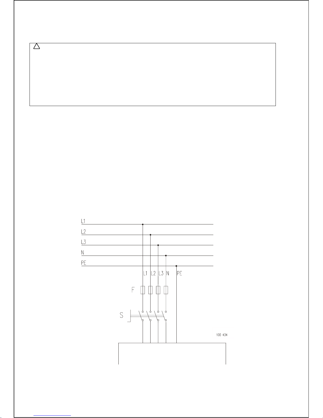
4.5.3. SUPPLY CABLE AND SAFETY DEVICES
Fig. 4.5.3. Ex ampl e of elec trical connection
!
MACHINE
Page 14
100646 PUBLICATION DATE Sep 05 INSTALLATION AND MAINTENANCE MANUAL 13
Supply cable of the mac hine m ust hav e c opper wir es. The cross section of the supply wires depends
on the supply voltage and on the total electrical power input of the machine (see chapter 3). The supply cable
saf ety device against a short-circui t fault a nd overl oading must be performed by automatic break ers or fuse s
in the laundry switchboard. The recommended minimal cross-section of the supply wires as well as the values
of fuses (F) for the supply ar e stated in table 4.5.3.
In all cases were the local standards requirements are higher, these has to be followed above the recommendation
in table 4.5.3. If the local standards require installation of the earth leakage trip, we suggest to install one of 100 mA
for the machines equipped with frequency inverter. The main contacts of the earth leakage trip must comply
with the specified power i nput of the machine.
Power supply
protection (A)
Recommended phase
conductor section
(mm2)
Protection conductor
section (mm2)
16 2,5 2,5
25 - 32 4 4
40 6 6
50 10 10
60 - 80 16 16
Tab 4.5.3. Recommended mi nimal conductor section
4.5.4. INSTALL SUPPLY CABLE TO THE MACHI NE
WARNING !
THE PROTECTIVE CONDUCTOR MUST BE LONGER SO THAT WHEN THE CABLE IS PULLED OUT
ACCIDENTALLY, THIS CONDUCTOR IS DISCONNECTED AS THE LAST ONE!
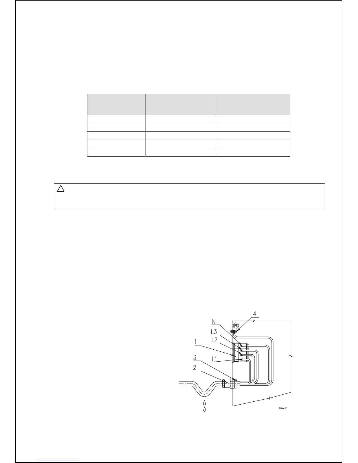
Push the cable through the turnbuckle and connect the wires with the main switch. The diameter of the supply
cable must between 11-17mm / 0.43 - 0 . 6 7“ for M25 turnbuckle and between 12- 21 mm / 0.47-0.8 3“ for M32
turnbuckle. Conductors of the supply cords shall not be consolidated by lead-tin soldering where they are subject
to contact pressure, unless the clamping means is constructed so that there is no risk of a bad contact due
to cold flow of the solder. The phase terminals are marked by L1, L2 and L3. A separate insul ated terminal,
labeled N, is provided for the neutral wire. Connect the protection eart h wir e dir ec tly to the protection earth
terminal (marked PE) located on the rear bridge. Tighten the cap nut of the turnbuckle. By this way the rubber
ring in the turnbuckle is pressed, thus securing the cable mechanically and against water. If there’s no main
switch the terminals are marked in the same way so also the connection is the same. Depending on your supply
voltage it is possible that L2 and L3 (1 AC) or N (3 AC without Neutral) must not be connected.
If the cable is attached f rom above, it is recommended to make a sagging on the cable in front of its entry
into the cable turnbu ckle. In this way an ingress of the runn ing conde ns ed wate r into the bus h and /o r machine
can be avoided. The manuf actur er recommends to attach the cable from beneath.
1. L1, L2, L3 and N terminal
2. Turnbuckle
3. Turnbuckle nut
4. PE terminal
Fig. 4.5.4. Ex ampl e of suppl y c able c onnec tion
!
Page 15
14 INSTALLATION AND MAINTENANCE MANUAL PUBLICATION DATE Sep 05 100646
4.5.5. CHECKING ROTATION DIRECTION
CHECK IF THE DRUM ROTATES FROM THE FRONT VIEW IN CLOCKWISE DIRECTION DURING
EXTRACTION. IF IT ROTATES IN OPPOSITE DIRECTION, DISCONNECT TWO PHASES
OF THE CONNECTION FROM THE FREQUENCY INVERTER TO THE MOTOR , SWITCH THEM OVER
AND CHECK AGAIN THE ROTATION DIRECTION.
Fig. 4.5.5. Spin direction
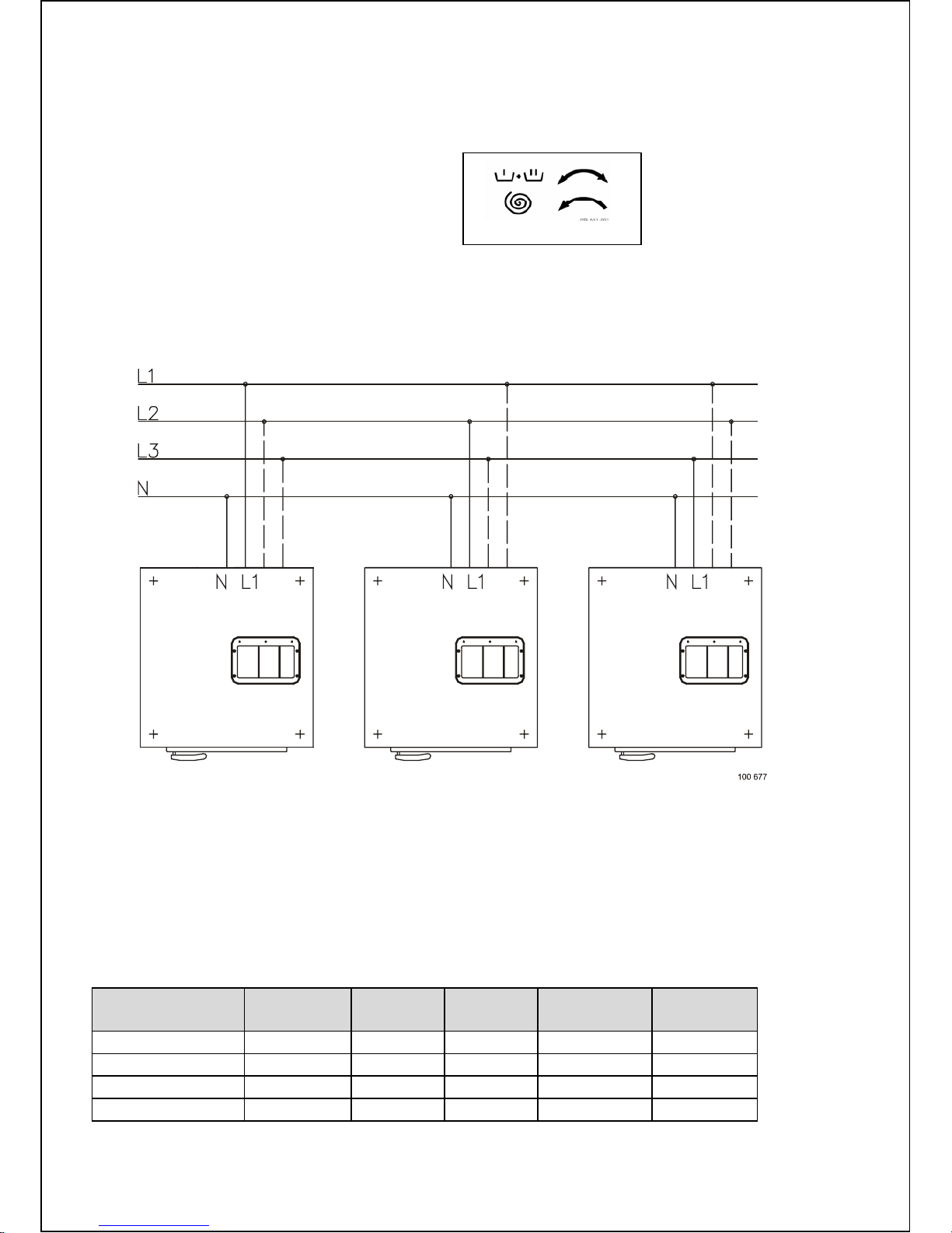
4.5.6. MULTIPLE MACHINES IN LINE SIMPLE PHASE
When multiple single phase machines are connected to the same electrical network, it is necessary to connect
the machines according to fig. 4.5.6. The phase of the frequency control and motor which is connected
to the terminal inside the machine, has to be connecte d alternatively for the first mach ine w ith the firs t phase
L1 of the network, the second m achine with the second phase L2, ... The fourth machi ne must again be
connected to the first phase L1. This assures a better load of the electri c al network.
Fig. 4.5.6. Multiple machines in line
4.6. CONNECTION OF WATER S UPPLIES
WATER CONNECTION
WATER HARDNESS
It is advisable t o contac t the water supplier for information concerning the properties of the water in your
area. Good wash results are dependent also on the water hardness. For medium to ver y hard water,
consideration shoul d be m ade to make the water softer.
Only in some cases is the use of hard water desir able, such as adding softener in the linen.
The soap supplier c an help y ou with m aki ng the right decisions concerning hard water, sof t water, washing
programs, ty pe of soap and other r elated items to have the best wash results.
Characteristics mm ol / dm
3
dH -
Germany
fH -
France
England
gr/gal
USA
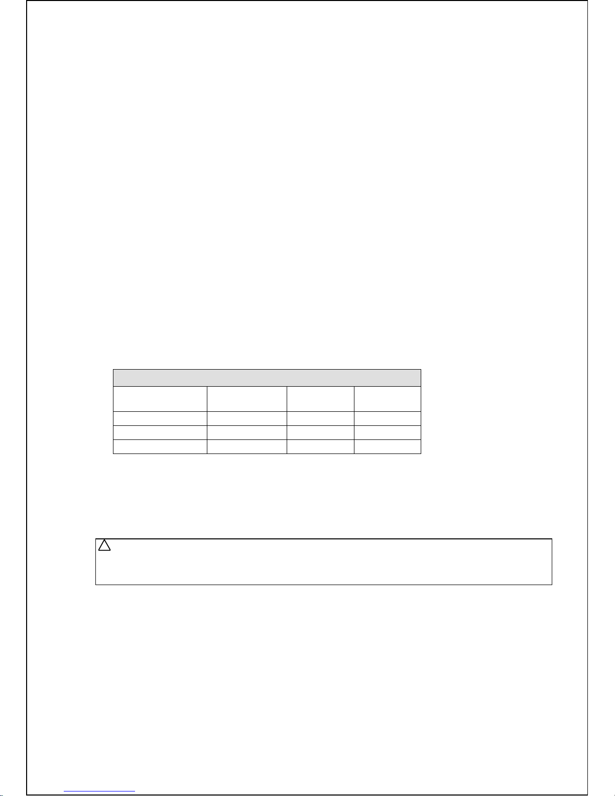
soft 0 - 1,25 0 - 7° 0 - 12° 0 - 8,75° 0 - 3
medium 1,25 - 2,5 7 - 14° 12 - 25° 8,75 - 17,5° 3 - 7
hard 2,5 - 3,75 14 - 21° 25 - 37° 17,5 - 26,3° 7 - 15
very hard above 3,75 above 21° above 37° above 26,3° above 15
Tab.4.6.A.
Page 16
100646 PUBLICATION DATE Sep 05 INSTALLATION AND MAINTENANCE MANUAL 15
HOT WATER
When the machine is provided with a hot water inlet, we advise connecting this inlet to a hot water supply
that is set to 70°C / 158°F. The hot water suppl y needs t o be large enough to provide the required hot water
for the washers.
WATER CONNECTION
Most machines are made wit h 2 or 3 water i nlets. One is always marked with „soft water“. If mor e inlets are
present, they are mar k ed wi th „Hot water“ or „Hard water“. For connection dimensions see fig. 3.1. Always
use the flexibl e hose delivered with the machine, if not present, c ontact your dealer. In each case do not
use a fixed connection to the water supply.
For the proper functi on of t he m ac hi ne, it is necessary to keep the water pressure within the limits stat ed
in the technical data. It is also necessary to connect all available water inlets to a water supply. If a hard water
supply is not present, c onnect it with soft water. If no hot water supply is present, c ontact your dealer for
the proper requir ed action.
The machine is equipped with 3/4" inlet valves. First let the water fl ow from the t ap into the drain before
connecting t he machine to the water system. This is for cleaning the pipes fr om dirt. Otherwise the filters
could be stopped up.
Open the taps and check the connection points at the taps and at the inlets of the machi ne for tightness.
If water is leaki ng, c or r ect the position of the seal and tighten the screw coupling.
WATER CONSUMP TION
The water consumption depends on the programmed values in the timer. These values are shown in the program
manual. For a prewash and wash the low water level (LL) is used. The high water level (HL) is used for rinsing.
The programmed units corr espond t o an average amount of water. You can calculate the total water
consumption in one washing progr am by counting up the amount of water by each washing step.
An example is shown for a system with cold and warm water supply for a machine with capacity of 10kg / 22lb.
A system without warm water suppl y y ou c an c ount with the total amounts.
Program (60°C / 140F) Light soiled linen
Consumption
Cold water
(liter / gal)
Warm water
(liter / gal)
Total
(liter / gal)
1. Wash 60°C 15 / 3.96 16 / 4.22 31 / 8.18
2. Rinse (3x) 46 / 12.15 - 138 / 36.45
TOTAL 61 / 16.11 16 / 4.22 169 / 44.64
Tab 4.6.B. Water consum ption
The values received from this calculation is only an estimation of the real water consumption. The deviation
depends on many circumstances. In the wash cycle for example there will be taken a mix of warm water
and cold water. The mix of the water depends on the temperature of both. The total amount of water consumed
depends also on the loading of the drum with linen and the turning of the drum.
STEAM CONNECTION
WARNING !
BEFORE EVERY STEAM VALVE IT IS NECESSARY TO INSERT THE FILTER WITH PERMEABILITY
UP TO 300 MICROMETERS. POSSIBLE DIRT BIGGE R THAN 300 MICROMETERS MIGHT DAMAGE
THE STEAM VALVE AND CAUSE ITS LEAKAGE.
Machines with steam heating have a device for a steam connecting, see fig. 3.1, pos.12) with diameter 1/2“
in rear left part. Use inlet steam pressure hoses, adapted to the valves with seal. The cond ition for proper funct ion
of inlet valves is the pr es s ure between (0,1 - 0,3 MPa / 14,5 - 44 PSI - applicable for steam pressure low) ,
(0,3-0,8 MPa / 44-116 PSI - applicable for steam pressure high).
WATER DRAIN CONNECTION
The machine is equipped with a drain valve of 76 mm (3“) diameter. The drain is situat ed on the rear
of the machine. The drain has t o be c onnec ted to the waste channel. You can use the elbow, which is a part
of the delivery. Secure the elbow with a clamp.
THE WASTE CHANNEL MUST BE LOCATED LOWER THAN THE DRAIN PIPES BECAUSE THE WATER
DISCHARGES FROM THE MACHINES BY GRAVITY. DO NOT REDUCE THE DIAMETER OF THE MACHINE
DRAIN PIPES.
!
Page 17
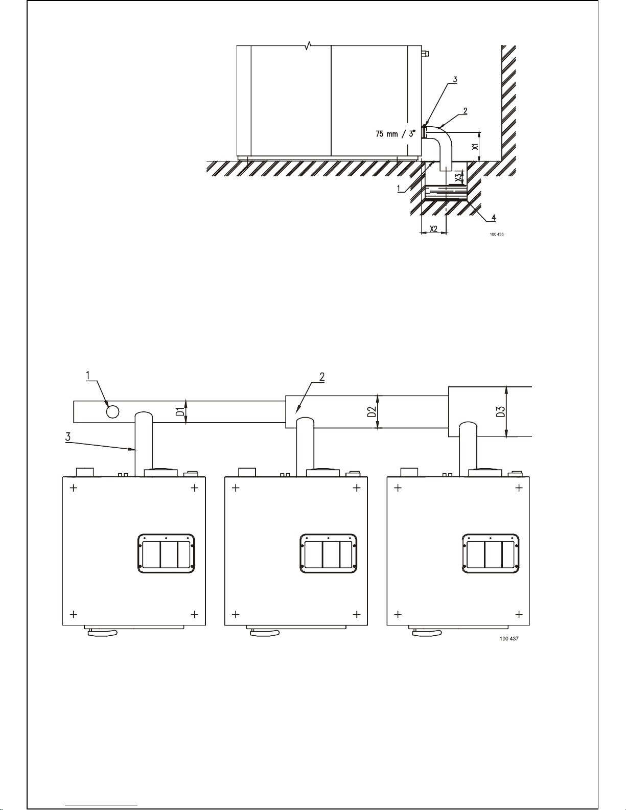
16 INSTALLATION AND MAINTENANCE MANUAL PUBLICATION DATE Sep 05 100646
1. Waste channel cover
2. Drain elbow ∅76mm / 3“
3. Clamp
4. Waste channel
Without rubber feet :
X1 = 55mm / 2.16"
With rubber feet :
X1 = 73mm / 2.87"
X2 > 100mm / 3.93"
X3 > 20mm / 0.78"
Fig. 4.6.A. Design of the waste channel
The main drain pipe must have the capacity to be able to handle the total output of all c onnec ted machines.
There must also be a hole every twenty meter in the drainpipe, fig. 4.6.B, pos. 1 to assure the good worki ng
of the drain. This allow s air in the ma in dra in and fa c ilitates drainage of the water flow. E very time a mach ine
is coupled on the drainpipe, the diameter of the tube or the width of the waste channel m ust be m or e. S ee,
fig. 4.6.B, D1, D2, D3.
The recommended drain pipes diameter are:
D1 = 75 mm / 3“ for one machine
D2 = 100 mm / 4“ for two machines
D3 = 125 mm / 5“ for three machines
If the main drain cannot be sufficiently deodorized, instal l a deodor izer per machine.
Fig. 4.6.B. Recommended drain pipe diameters
Page 18
100646 PUBLICATION DATE Sep 05 INSTALLATION AND MAINTENANCE MANUAL 17
AIR VENT CONNECTION
WARNING!
WATCH OUT, VAPOURS ESCAPE FROM THE MACHINE THROUGH THE AIR VENT OPENING!
DO NOT COVER OR CONNECT TO ANYTHING!
On the backside, the washers are prov ided with an air vent opening of O.D. 75 mm / 3".
Do not cover the washer air v ent opening. It is part of the back flow prevention water system. It also takes
care that the tub can not be pressuri z ed by water intake and vapor of the hot water, this all ows for pr oper
measuring of the water level.
For the safety of everyone m ak e sure t hat unauthorized persons cannot reach the backside of the machine.
4.7. CONNECTION OF LIQUID WASHING SOAPS DOSING
It is possible to connect an external dosing of liquid soaps to the machine.
WARNING !
DISCONNECT THE MACHINE SUPPLY POWER INLET BEFORE INSTALLATION.
THE INLET TERMINALS ARE UNDER CURRENT EVEN WHEN THE MAIN SWITCH IS OFF
ELECTRICAL CONNECTION AND CONNECTING T HE MACHINE I NLETS M UST BE CARRIED OUT
BY AUTHORIZED WORKERS ACCORDING TO INSTALLATION MANUAL I NSTRUCTIONS AND IN
ACCORDANCE WITH VALID LOCAL STANDARDS.
AFTER THE HOSES ARE CONNECTED PUT ALL MACHINE COVERS BACK TO THEIR PLACES.
For connecting t he liquid soap inlets and wiring for machines 6kg / 13lb, 7kg / 16lb, 10kg / 22lb you must take
of the top panel. Unscrew the two bolts and t ak e the top panel of the machine. For 16kg / 36lb machine it is
sufficient to open the top panel by means of the two key switches at the front.
At the right side panel there i s a support for the top panel.
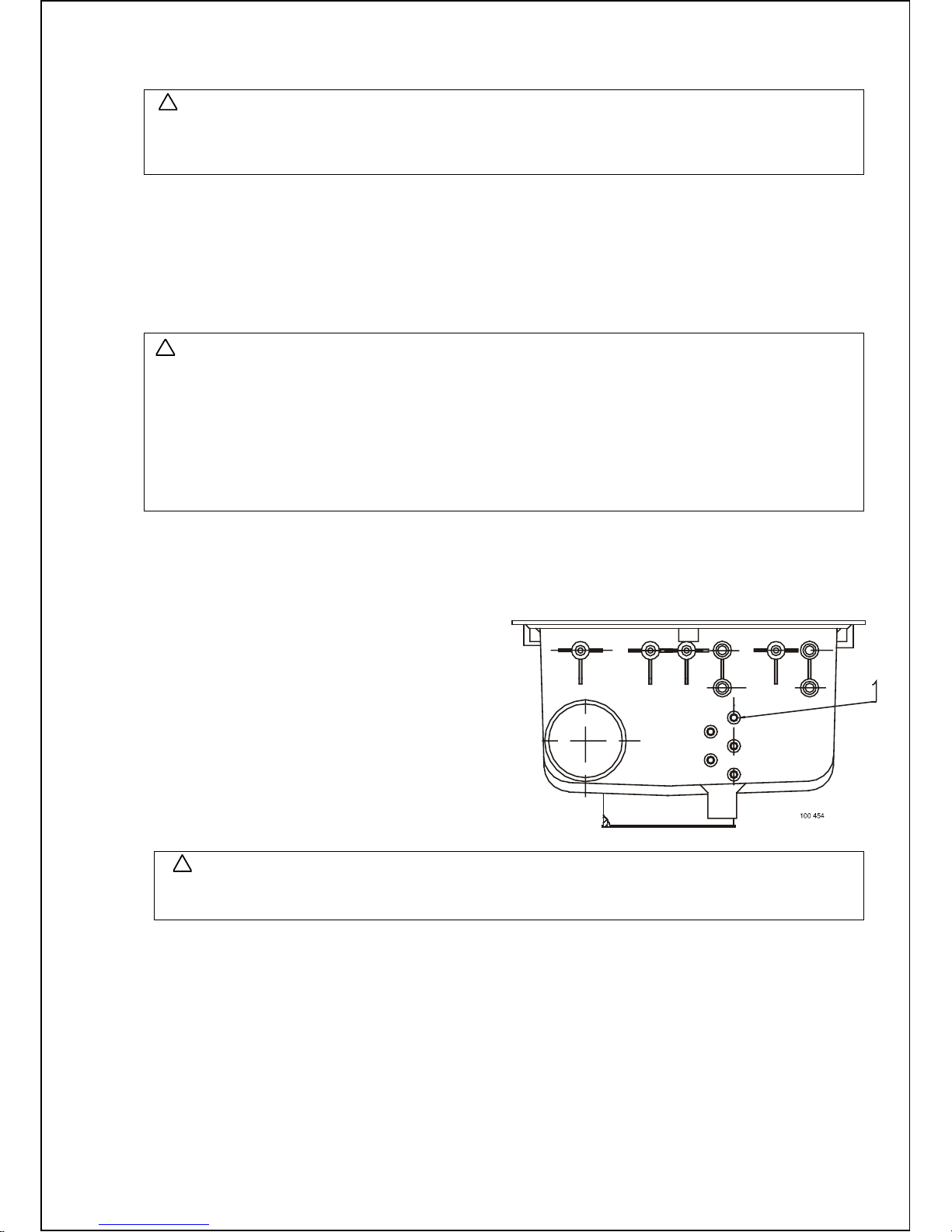
The hoses of external dosing of liquid soaps are
pushed through the hol es i n the rear panel after
removing the plugs. The hoses should be protected
by rubber bushings where penetrating the rear panel.
After this make as many hol es i n the soap hopper,
fig. 4.7.A, pos.1) as you have liquid soap hoses.
Connect the hoses to the soap hopper by m eans
of clamps.
Fig 4.7.A. Connecti on soap hopper
WARNING !
CHECK IF THE HOSES ARE TIGHTEN BY THE CLAMPS !
ANY LEAKAGE OF CHEMICALS MAY CAUSE CORROSION ON THE PARTS IN THE MACHINE.
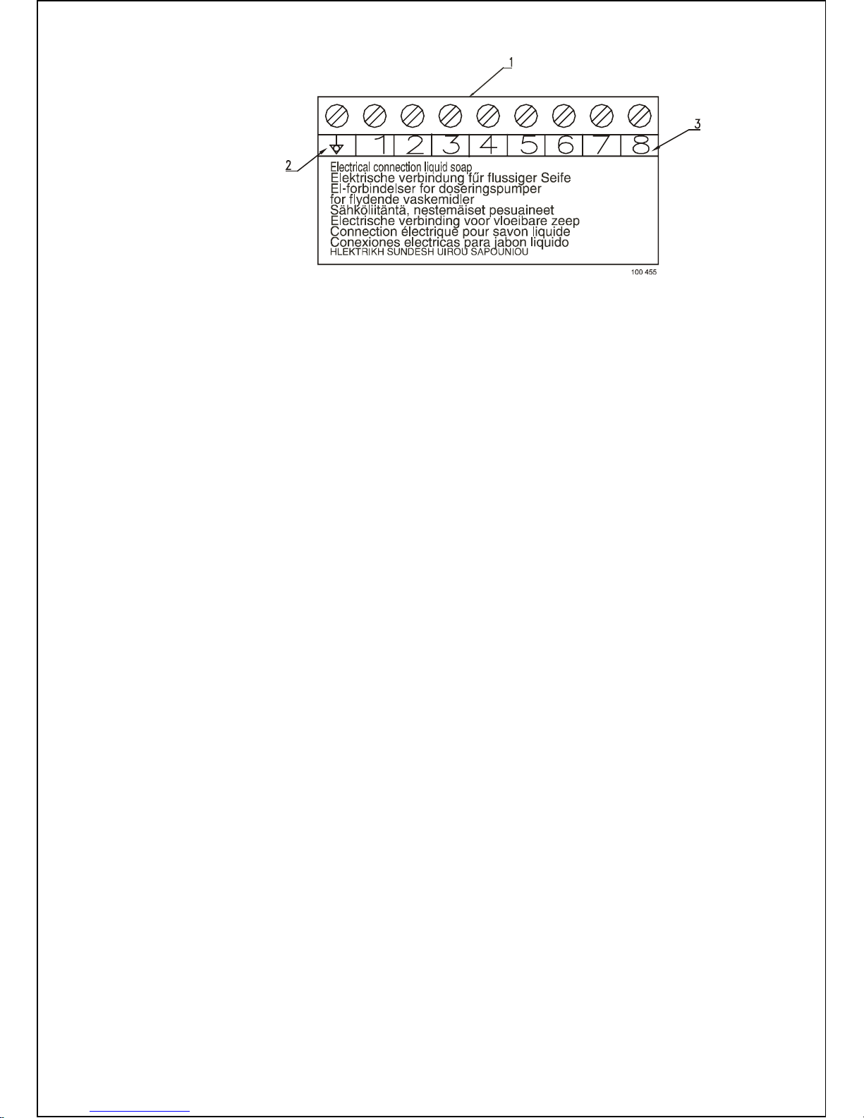
The liquid soap pump system supply needs to be connected to an external electrical source. Only authorized
workers with a valid qualification must execute the electrical connection of the machine according to the valid
local standards. Do not connect the pum p system in the machine. The liquid soap signals are avai lable
in the machine on a conn ec tor, see fig. 4.7.B. The first terminal is the co mmon line of the signals. The following
terminals are the signals that will be active depending of the programmed wash program. These signals have
a potential of max. 250V. Use a cable that is sufficient for their function and pass it in the appropr iate opening
in the machine. Connect t h ese signal t ermin als l ik e the m a nufac t u rer of the liquid soap system requires.
The liquid soap system m ay draw maximum 0,1A out the control circuit of the washer-extr ac tor.
!
!
!
Page 19
18 INSTALLATION AND MAINTENANCE MANUAL PUBLICATION DATE Sep 05 100646
1. Terminals for connection
liquid soap pumps
2. Neutral line
3. Soap signals
Fig. 4.7.B. Elect rical connection soap pumps
4.8. PREPARING THE MACHINE FOR OPERATION
CHECKING BEFORE PUTTING INTO SERVICE
1. Make sure the transporting braces are removed.
2. Put out all thi ngs fr om wash drum.
3. Check the machine hor iz ontal position.
4. Check connection and clearance of your drain, channel or central drai nage.
5. Check protective connection (earthing) and electrical supply connection.
6. Open water valv es to m ac hi ne and c hec k hose and connections for leaks.
7. Read caref ully the „User´s manual“ and „Programming manual“, which are a part of delivery.
8. Initi aliz e the programmer after machine install ation. The calibration of the zero level must not happen
anymore. This cali bration is executed in the factory and is not changeable.
9. Check the drum r otati on direction during extracting ac c ording to the extrac ting label.
10. Check the vibration switch function during extr acting (see also chapter 5.2 adjustments and parts
exchange, adjustment of the vibration switch.
11. Check the emergenc y function.
Page 20
100646 PUBLICATION DATE Sep 05 INSTALLATION AND MAINTENANCE MANUAL 19
5. MAINTENA NCE AND ADJUSTMENTS
WARNING !
ALWAYS FOLLOW SAFETY INSTRUCTIONS! DO NOT BYPASS ANY SAFETY DEVICES OR THEIR
PARTS, ANY INTERFERENCE TO THE MACHINE FUNCTIONS AND CONSTRUCTION ARE PROHIBITED.
BEFORE MAINTENANCE WORK DISCONNECT T HE MACHINE PO WER S UPPL Y.
USE THE PROPER CHEM ICAL AGENTS W HICH AVOID CAL CIUM SEDIMENTS ON HEATING EL EMENTS
AND OTHER MACHINE PARTS. DISCUSS THIS ISSUE WITH YOUR SUPPLIER OF WASHING PRODUCTS.
THE MANUFACTURER OF THE MACHINE IS NOT RESPONSIBLE FOR THE DAMAGE OF HEATING
ELEMENTS AND OTHER MACHINE PARTS DUE TO CALCIUM SE DIME NTS.
In case of serious failures call the technical service of your supplier. When replacing any parts of the machine,
exchange them with original parts obtained from your dealer or order ed through the spare parts catalogue.
5.1. MAINTENANCE
CHECKING AND MAINTENANCE DAILY
1. Remove the li nen or other parts (paperclips, needles, …) who are left lying in the dr um to av oid injuries
and damage to the rubber door seal , seals, glass etc.
2. Clean the door seal from any remaining detergent and other foreign matter.
3. Clean the top and body when water or detergent traces are on the machine. Use a damped cloth, do not use
abrasive cleaners. Dr y with a soft cloth.
4. Hoppers must be cleaned at the end of each working day. Remove sediments inside the reservoir by means
of a plastic spatul a and spl ash by water.
5. Check water and possibl e st eam inlets for leakage.
6. At the end of the working day, open the machine door to allow airing out the machine and to prolong the door
gasket lif e servic e. We recommend to shut off all electrical power inlets and main water inlets.
CHECKING AND MAINTENANCE EVERY THREE MONTHS
WARNING !
HOT MACHINE PARTS SHOULD BE ALLOWED TO COOL FIRST !
1. Check if the drain valve is not leaking during the wash process.It is also important that the valve opens
properly afterward s (dr ain valve opens when electrical power f alls out).Wash out the drain if the water
doesn’t drain fl uent.
2. Check for the bel t ti ghtness or possible damage; therefore remove the machine rear cover.
3. Check the tightness of the bolts according to chapter 5.2.
4. Check visuall y all hoses and connection inside the machine for leaking.
5. Make sure that t he control components are protected against moisture and dust dur ing the clean up.
Wipe and clean up the machine insi de.
6. Tight en the contacts of heating elements terminals on machines with elec trical heating.
CHECKING AND MAINTENANCE EVERY SIX MONTHS
1. The filter s i n the water c onnec tion at the valves need to be cleaned. Turn off the tap. Unscrew the hoses
at the back of the appliance. Take out the filter at the center with pointed pliers, clean and re-insert.
When re-attac hing the hoses, make sure that the seals are seated correctl y . Check water inlets for leaks.
Tighten the connections or replace the seals of the inlet hose if necessary.
BEFORE REMOVING TOP OR BACK PANEL OF THE MACHINE, SWITCH POWER OFF AND WAIT
FOR AT LEAST 10 MINUTES. BEFORE ST ARTING INSPECTION OF FREQUENCY INVERTER,
CHECK FOR RESIDUAL VOLTAGE ACROSS MAIN CIRCUIT TERMINALS + AND -. THIS VOLTAGE
MUST BE BELOW 30V DC BE F ORE YOU CAN ACCESS THE INVERTER FOR IN S PECTION.
2. Clean and remove dir t and dust f r om:
– the cooling fin of the inverter
– the motor cooling fins
– the internal ventilator of the inverter (if present)
– the ext er nal v entilator (if present)
– the ext er nal air relieves of the machine
– check if v entilator in coolfins of inverter (if present) is functional
– check if exter nal ventilator (if present) is functi onal
!
!
!
Page 21
20 INSTALLATION AND MAINTENANCE MANUAL PUBLICATION DATE Sep 05 100646
5.2. ADJUSTMENTS AND PART´S EXCHANGES
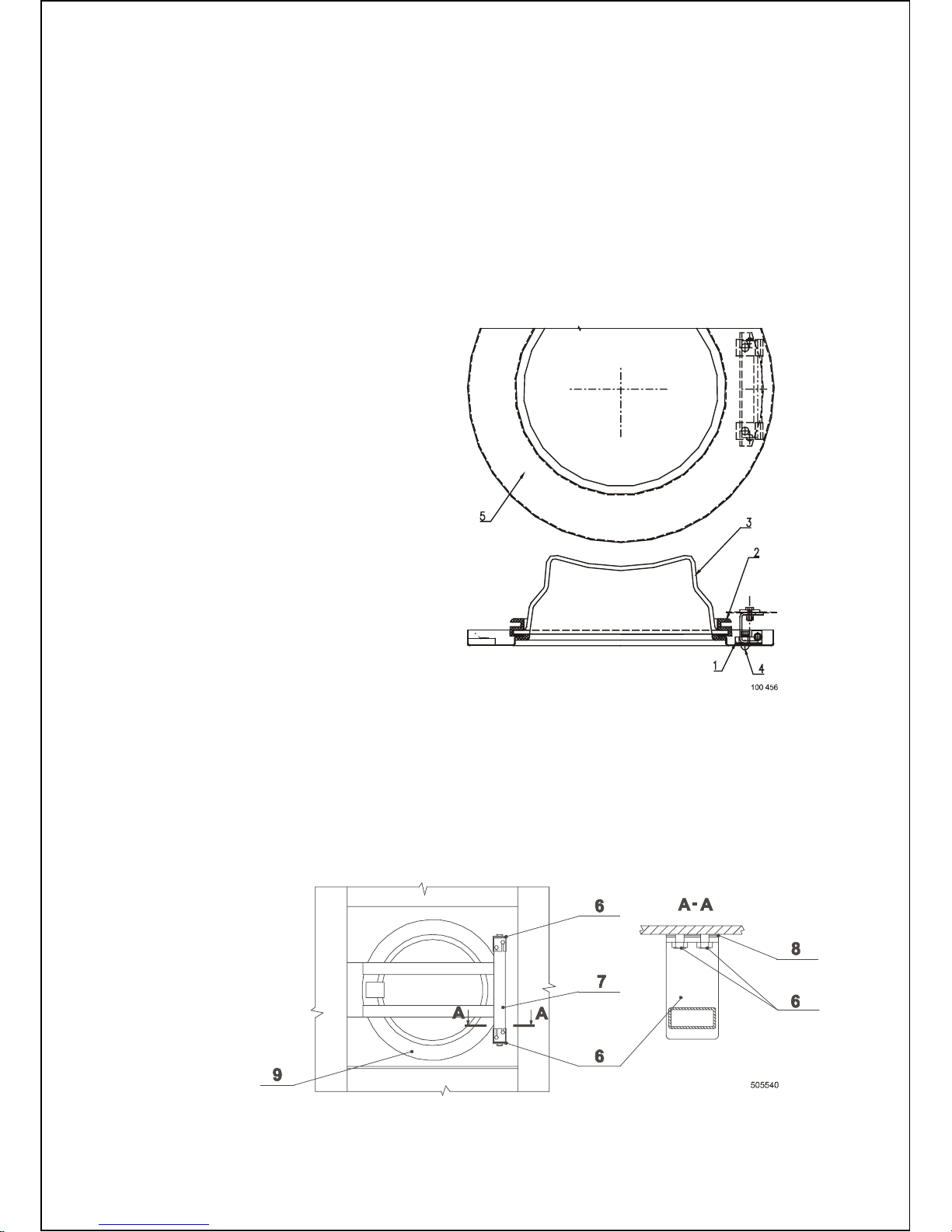
ADJUSTMENT OF DOOR SEAL THRUST
MACHINES 6kg / 13lb, 7kg / 16lb, 10kg / 22lb
If there is a water leakage around the door it is necessary to find out if the problem has been caused due
to the door shift out of its position or if the door seal thrust should be adjusted. In some cases the door seal
has to be replaced. (fig. 5.2.A).
1. For increasing (decreasing) the pressure of the door seal, take off spacers (pos.1) (add spacers) between
the door frame and the hi nge bloc ks. Therefore remove the screws (pos.4) on the door fr am e. Ti ghten
the screws again after positioning the spacers.
2. The adjustments of the door seal pressure must be executed as follows. The door rubber ( pos.2) must
still touch the tub rubber at the hinge side when the door opens at 5°.
3. Adjust the position of the door by loosening the screws (pos.4) on the door frame. The door hook must be right
in the center of the door lock opening. Tighten the screws (pos.4) again after correct positioning of the door.
1. Adjusting spacers of the door hinge
2. Door seal
3. Door glass
4. Bolts of the door hinge
5. Door frame
Fig. 5.2.A. Door fastening
MACHINES 16kg / 36lb
1. Loosen two bolts (6) f ast ening the top door hinge (7), fig. 5.2.B.
BE CAREFUL TO AVOID POSSIBLE FALLING OF THE DOOR WITH LOOSENED HINGE TO THE
FLOOR. RISK OF INJURIES!
2. Take off the elimi nation washer (8).
3. Tighten the two bolt s (6) fastening the top door hinge.
4. Do the same with the bottom hinge.
5. Check if the door hinge has not moved, closing and opening of the door must be smooth.
If the thrust adj usting has not been sufficient, exchange the door seal.
6. Hinge bolt
7. Hinge
8. Eliminati on washer
9. Door
Fig. 5.2.B. Door fastening
Page 22
100646 PUBLICATION DATE Sep 05 INSTALLATION AND MAINTENANCE MANUAL 21
REPLACEMENT OF DOOR RUBBER
MACHINES 6kg / 13lb, 7kg / 16lb, 10kg / 22lb
1. Open the door. Remove the door glass (Fig. 5.2.A, pos.3) with rubber (pos.2) from the stainless steel door
(pos.5) by pushing it towards t he dr um . Do it carefully, do not damage the glass.
2. Remove the seal (pos.4) fr om the glass.
3. Place a new rubber seal with wider groove on the glass with the edge up.
4. Moisten the seal gr oov e (pos.2) for door with soap water. Place a smooth cord in the groove all ar ound.
Tighten up the margin by cord and fit the unit to the door opening (pos.5) (with the clip up). Hold one end
of the cord firmly on the door . Pull the other cord end towards the center of the glass for t he r ubber edge
properly fit in.
ADJU STING OF VIBRATION SWITCH
WARNING!
MAKE SURE THE MACHINE IS DISCONNECTED FROM POWER SUPPLY BY PULLING OUT THE PLUG!
The vibration switch is an important safety element which must - if cor r ectly adjusted - stop the machine
if excessive vibr ations and shaking occur due to an unbalance caused by improper distribution of linen
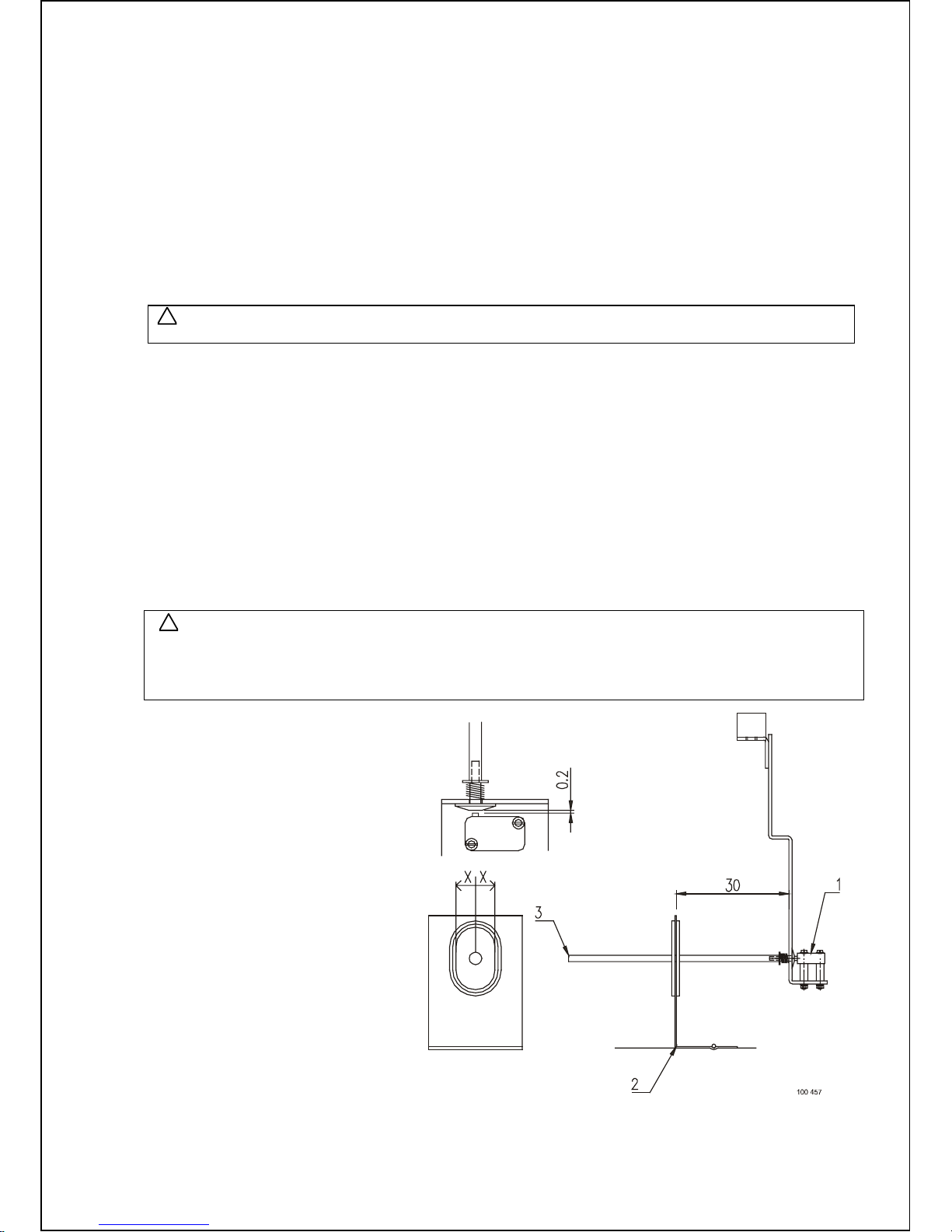
in the washing drum. It is recommended that at the first installation and then once in a year a qualified worker
verifies the vibr ation switch, fig. 5.2.C.
5. Dismantl e ( 6k g / 13lb, 7kg / 16lb, 10kg / 22lb) the top cover by two bolts on machine rear for machines.
For the 16kg / 36lb the top cover can be folded open and supported by the support at the right side panel.
6. Check the di stanc e between microswitch (pos 1) and the limiter (pos 2).
7. The distance between the microswitch and the spring holder must be 0,2mm / 0.008“.
8. Check the positi on and c ondition of the sensor (pos.3) in the limiter (pos 2).
It must be exactly in the center of the hole! Unscrew the tiltswitch plate and move the plate up, down, left
and right to adjust the center of the sensor to the center of the hole on the limiter.
9. At the first installation and then once in a year the vibration switch has to be tested on his functionality.
After starting the extraction mode and after reaching the maximum RPM, carefully switch over the vibration
switch by moving the flexi ble sensor manually. The machine will stop extracting and will return to 0 RPM.
WARNING!
DO NOT OPERATE THE MACHINE IF THIS FUNCTION DOESN’T WORK ANYMORE!
DO THIS CAREFULLY TO AVOID INJURIES BY VIBRATING AND FIRM PARTS OF THE MACHINE!
AFTER YOU HAVE CHECKED THE FUNCTION, MOUNT THE MACHINE COVER BACK!
1. Microswitch
2. Limiter
3. Sensor
Fig. 5.2.C. Vibr ation switch
!
!
Page 23
22 INSTALLATION AND MAINTENANCE MANUAL PUBLICATION DATE Sep 05 100646
REPLACEMENT / REGULATION OF THE BELT
WARNING!
MAKE SURE THE MACHINE IS DISCONNECTED FROM PO WER SUPPLY BY PULLING OUT THE
PLUG FROM THE SOCKET.
On a new machine and after a belt replacement, make an inspection of the belt tightness :
1. After first 24 hr s of oper ation
2. After first 80 hr s of oper ation
3. Every 6 months or ev ery 1000 oper ation hours - which ever come first.
The belts are accessible from the rear of the machine.
If the belts are too tight the bearing seating are under stress and their life service will be shortened. If the b elts
are too loose they can be slipping on the pulley and can cause a noisy operation. In the case when it’s needed,
tighten the belts.
MACHINES 16kg / 36lb
The testing force o f belt tens ioning is 200 N which can be me as ured by t ens ion meter. P roced ure for appro ximate
belt tensioning w ith belt de fle ction 20m m / 0. 78“ : apply a load of 5,5kg / 12lb to the midd le o f the be lt . Change
the belts if they are worn out or damaged.
T O CHANGE THE BELTS:
NEVER USE A CROWBAR TO TAKE OFF THE BELTS OVER THE PULLEY GROOVES!
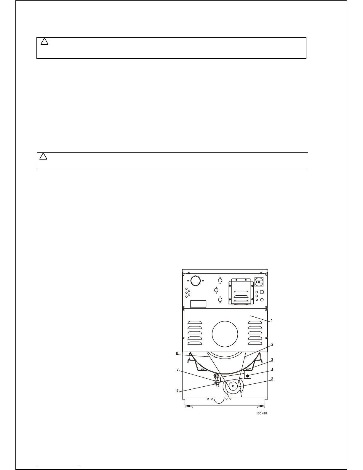
1. Dismantl e the rear panel, fig. 5.2.D, (pos.1).
2. Take off the belts, (pos.2.) by pulling the belt and turning the drum pulley (pos.5).
3. Put a new belt (2) of identical type on pu lleys (pos.5 and 8). The re-asse mbly o f the be lts is done in the reverse
order as the disassembl y.
4. The belt must be placed in the correct motor pulley trenches in such way the belt is runni ng in the center
of the drum pulley.
To tighten or loosen the belt tension :
1. Loosen the bolts (pos.4) for securing the motor position.
2. First unscrew the lower nut (pos.6) and then unscrew the upper nut (pos.7) for increasing the belt tension.
3. For decreasing the belt tension screw the lower and upper nut (pos.6 and 7) and lift the motor suspension.
After this tighten all the bolts.
4. After the belt replacement, check the pulley alignment, the tightness of belts, bolts and nuts. Keep the belts
and pulleys clean and fr ee of oil, lubricants, water etc.
1. Rear panel
2. 2 x Belt
3. 2 x Screw M12 : Alignm ent
4. 2 x Screw M10
5. Motor pull ey
6. Securing nut of bolt M16 (lower)
7. Securing nut of bolt M16 (upper)
8. Drum pulley
Fig. 5.2.D. Regulati on of belt
!
!
Page 24
100646 PUBLICATION DATE Sep 05 INSTALLATION AND MAINTENANCE MANUAL 23
WATER FILTERS
Machines are equipped with filters on water inlets. It is necessary to clean up the filters occasionally to avoid
a prolongati on of fill ing the machine with water. Intervals of cleaning depend on the quality of the water,
for example foreign par ticles in the water line.
WARNING !
BEFORE YOU START THE FILTER CLEANING CHECK IF THE INLET OF HOT WATER TO THE
MACHINE IS CLOSED AND COLD.
TIGHTENING MOMENTS
WARNING !
REGULARLY, ONCE IN THREE MONTHS OR EVERY 500 WORKING HOURS INSPECT THE
TIGHTNESS OF THE BOLTS !
REPLACE A DAMAGED BOLT WITH A BOLT OF THE SAME STRENGTH VALUE MARKED ON HIS
HEAD ! IGNORING OF THE BOLT QUALITY AND MECHANICAL STRENGT H CAN CAUSE SERIOUS
BODILY INJURIES !
The recommended tor que v alues for standardized steel bolts :
M6 8.8 : C = 10 Nm
M8 8.8 : C = 25 Nm
M10 8.8 : C = 45 Nm
M12 8.8 : C = 80 Nm
M16 8.8 : C = 200 Nm
The bolts that have to be inspected ar e :
Bolts which are used for the reinforcement triangles for the cabinet. This reinforcements are found in the front
(2 pieces) and in the back ( 2 pi ec es) of the m ac hine = 16 bolts M6 and M8.
Bolts for fixati on of bear ing house in tub M10 or M12.
FUSES
The internal fuses FU1, FU2 for controlling circuits have v alue 1A (230V or 400V ) and dimension L=32mm /
1.26“ and ∅ = 6,3mm / 0.24“. The fuses are accessible from the machine rear, fi g. 3.1., pos.7.
!
!
Page 25
24 INSTALLATION AND MAINTENANCE MANUAL PUBLICATION DATE Sep 05 100646
6. TROUBLESHOOTING AIDS
6.1. ERROR HANDLING
The timer allows the full control of the washing machine. When an error occurs then automatically the machine
will go over to a safe state. Wit h the diagnostic program you can determine the problem ( S ee „Progr amming
manual"). This program will test all the functions of the washing mac hine.
If a failure occurs then t he co mputer w ill display a diagnostic message. The message is a number that correspond
with a typical problem.
If a failure occurs and the timer gives no message you can consult chapter 6.2.
6.2. PROBLEM CHECK LIST
Problem Cause Solving the problem
When the power is switched on :
the display is not lighting up
Rem ark :
The displ ay m us t always light up
when the power connector is
connected to the power board
(EPROM with software must be
implemented)
• no exte rnal power
• the emerg ency button is activ ated
• the power connector is not
connected on the board
• the power connector is inverse
connected
• the fuse on the PWR board has
jumped
• the input connector is disconnected
• the EPROM that contains the
softwar e is not im pl em en ted
• verify the external tension of the
machine
• deactivate the emergency button
• connect the power connector
• check the wiring and connect the
connector as it m u st b e
• if the transformer is deformed replace
the PWR board
Check th e wiri ng and t h e tens i on at th e
power Connector
If the transformer is still OK change the
Fuse
• if the displ ay is ligh ting up: verify that
the input signals or the + 16 V signal are
not touching the cabinet
• put the right EPROM with software into
the socket on the board.
The machine is not starting up when
the start button is pressed.
• the key switch stands in Program
mode
• the correct amount of coins is not
inserted
• the door is not closed properly
• set the Key switch to Run mod e
• the start button must be pressed when
00 is flashing on the lower display
• close the door
Coins are inserted but the displayed
program pr ice is not countin g d ow n
• the micro contact mounted on the
coin drop is not fu nc tional
• the optocoupler mounted on the
coindrop is not functional
• check the wiring to the coindrop
• verify if you h av e entered a coin
value in the u-submenu for the
corresponding coindrop
• verify the w ell func tioning of the micr o
contact of the coindrop :
positive pulses should be generated
• verify the w ell func tioning of the
optoc oup l er p os iti ve p ulses should be
generated
• if the wiring is broken: repair the wiring
• insert the correct coin value in the u-
submenu
Coindrop is accepting coins but does
not start the washer
• the start button is not pushed aft er
the amount is flashing on ‘00’
• the right amount is not reached
• the door is not closed properly
• push the start button
•Put the right amount in the coindrop
• close the door
The machine is not responding on
pressing the keyboard buttons
• the key switch is not functional (no
dot is displayed when switching in
Program mode)
• the START button is not functional
(the key switch stands in Program
mode)
• the SET button is not functional (the
key switch stands in Run mode)
• no button is functional and the key
switch is in the rig ht p osit ion
• check if the input connector A is well
connected and check th e wir in g b etw e en
the input connector and the keyswitch
• set the Key switch to Run mod e
• set the Key switch to Program mode
• check if the connector K of the keyboard
is well connected
The dot to indicate that the s oftware is
in program mode can not be enabled
or disabled
• the key switch is not functional
• the infrar ed k ey is not fu nc t i on al
• check if the input connector A is well
connected and check th e wir in g b etw e en
the input connector and the keyswitch
• set the menu- it em , Ir = O n
Page 26
100646 PUBLICATION DATE Sep 05 INSTALLATION AND MAINTENANCE MANUAL 25
Problem Cause Solving the problem
use the key switch at a distance less
then 0,5 meter and in front of check the
battery (the LED of the infrared key is
eluminated when the button is pressed)
The machine is not behaving as
expected
• if the wrong mac hine type is
selected t h e wr on g outputs will be
activated
• the suspension is not working, the
shock abs or b er s are c old
• check if the right machine type is
selected in the S-submenu
• change shock absorbers or springs
A program is started, but the outputs
ar e not acti v a ted
• check if connector R and Q are
connected
• check if connector R and Q are not
inverted
• connect the connector at the correct
position
• Pin Q10 must be supplied with 220Vac
when the door is closed
Dashes ar e dis played and on th e
lower display a counter is counting
down
• this is a wait state caused by a
power int erruption or a safety
sequenc e at th e end of t h e pr oc ess
• wait until the counter has reached 0
• do not switch of/on the power again as
you will r est art t h e c ount er
Wrong wat er l evel
(the water level sensor must not be
calibrated)
• check if the programmed water
levels in th e P- s ub m en u are the
correct on es
• check if the right machine type is
selected in the S-submenu
• you have chan ged the machin e typ e
but the standard water levels are not
changed
• set the right water levels
• select the right machine type in the S-
submenu
• the standard water levels can only be
reinitialised by changing the program Set
in the S-submenu : standard wash
The process is stopped and there is
still water in th e dr u m
• you c an start a new program and
advance the program to the tumble
sequence
• the drain is stopped up
• the drain val ve is bl oc k ed
• advancing a program : turn the key
switch in program-mode and press the
start button
When the water is drained you c an open
the door
• clean the drain
• clean the drain valve
The wat er does n ot st ay in th e
machine
• the drain val ve is not cl osing
• leakage of rubber between tub and
drain val ve
• check wiring from drain valve
• change dr ain val ve w h en brok en
• Replace rubber piece
Machine is not filling or filling time is
too long
• inlet taps are closed
• water pressure too low
• water is blocked somewhere
• inlet valve filter is blocked
• inlet v alve is damaged
• open inlet t aps
• look at your supply installation
• check for kinks in the inl et hos e
• close wat er inl et and cl ean filter
• replace in l et val ve
Machine is filli n g wi th wat er in th e
‘OFF’ position
• inlet v alve is damaged • replace inl et valve
Machine is leak i ng
• clamps of hos es are not tight en ed
• some ho se is damaged
• sealing is damaged
• supply and drain hoses are n ot
connected properl y
• tighten the clamps
• replace the hose
• change the sealing
• connect the hoses properly
There is a door s eal leakage
• the door rubber seal is damaged
• insuff ic ient d oor pr ess ure
• change the door rubber seal
• remove spacers from behi nd the hinges
There is no warm water in the wash
sequence
• program is not correct
• the hoses are not correct connected
• incoming supply is not warm
• change program to correct temperature
• connect the supply hoses correctly, the
incoming supply to the warm water inlet
valve.
• use warm water supply, check your
warm water installation
The heating time is too long
• heating el em en ts ar e d ef ecti v e
• wiring is dam ag ed or wrong
• calcium sediments cover the
heating el em ents
• change heating elements
• check, replace or repair wiring
• clean or replace the heating elements
There is too m uc h vi bration durin g
extracting
• bolts of cabinet and reinforcements
are not fixed properly
• vibration switch is not correct
installed
• the suspension is damaged, the
• tighten the bolts
• reinstall vibration switch
Page 27
26 INSTALLATION AND MAINTENANCE MANUAL PUBLICATION DATE Sep 05 100646
Problem Cause Solving the problem
shock abs or b er s are c old
• change the shock absorbers
Door fails to open
• a fault is occu rred
• power is off, sa fety is working
• power is off, after a couple of
minutes waiting the door is jammed
• wait until the counter has reached ‘0’
• wait until s af ety devic e is in acti v e
• you can always open the door by the
mechanical override, be sure the machine
is stopped sp inning and ther e is n o hot
water anymore in the tub.
Machi ne will not spin
• a fault in the program is made
• wiring is damaged
• V-belts ar e br ok en
• Motor is broken
• Frequency converter is damaged
• check the program
• check and replace wiring
• replace the V-belts
• repair or change motor
• repair or replace the frequency
converter
Th e re is a lack of st e a m
• leak in steam system
• too many condense in the steam
system
• too much mach ines on 1 suppl y
• repair the leakage
• Remove the condens
• Disconnect other machines or increase
steam capacity
6.3. DOOR FAILS TO OPEN
In case of a power failure or an em ergency si tuation, proceed as follows:
1. Befor e the door is open, c hec k the washi ng bath and machine parts temperature.
WARNING !
IF TOO HOT DO NOT OPEN! RISK OF BURN OR SCALD INJURIES !
KEEP CHILDREN OFF WHEN THE MACHINE IS IN OPERATION !
2. When the washing bath i s cooled down, find the lever of emergency door opening on the left bot tom side
pull the lever by a screwdriver (∅ 4 mm / 0.15“) to open the door.
WARNING !
IF THE WASHING WATER WAS NOT DRAINED OFF, IT WILL RUN OUT THROUGH THE DOOR OPENING !
!
!
Page 28
100646 PUBLICATION DATE Sep 05 INSTALLATION AND MAINTENANCE MANUAL 27
7. LIST OF RECOMMENDED SPARE PARTS
Find more detail ed information in the spare part manual for individual machines.
PRI 340 055 051 Drain valve 3“ 230V
PRI 340 020 035 2-way water inlet valv e
PRI 340 030 038 3-way water inlet valv e
273 112 994 945 Rubber for door glass, appl icable for 16kg / 36lb
PRI 505 000 045 Rubber for door glass, appl icable for 6kg / 13lb, 7kg / 16lb, 10kg / 22lb
PRI 610 011 077 Microswitch 83. 161.3
PRI 530 030 012 Rubber tub housing, appl icable for 16kg / 36lb
PRI 530 020 012 Rubber tub housing, appl icable for 6kg / 13lb, 7kg / 16lb, 10kg / 22lb
PRI 530 030 013 Ring, applic able for 16kg / 36lb
PRI 530 020 013 Ring, applic able for 6kg / 13lb, 7kg / 16lb, 10kg / 22lb
514 038 Contactor of frequenc y inv er ter LC1-D09
514 038 Heating cont actor , LC1-D09, 6kW / from 200 to 440V, 9kW / 400V, 12kW / 400V
514 039 Heating cont actor , LC1-D12, 9kW / 230V
514 042 Heating cont actor , LC1-D18, 18kW / 400V
PRI 345 002 019 Heating contactor , LC1-D32, (12kW, 18kW) / 230V
345 805 163 032 Fuse 1A 32x6.3
PRI 401 022 021 Fuse 0,5A, 200-208V / 440V
PRI 342 000 011 Heating element 2000W 230V, electrical heating 6kW, applicable for 6kg / 13lb,
7kg / 16lb, 10kg / 22lb
PRI 342 000 028 Heating element 3000W 230V, electrical heating 9kW, applicable for 6kg / 13lb,
7kg / 16lb, 10kg / 22lb
PRI 551 002 217 Heating element 2x2000W 230V, electrical heating 12kW, applic able for 16kg / 36lb
PRI 342 000 032 Heating element 2x3000 W 230V, electrical heating 9kW, 18kW, applicable for 16kg / 36lb
PRI 342 000 040 Heating element 2x1500 W 230V, electrical heating 9kW, 440V, applicable for 6kg / 13lb,
7kg / 16lb, 10kg / 22lb
PRI 342 000 031 Heating element 2x2000W 230V, electrical heating 12kW, applicable for 6kg / 13lb,
7kg / 16lb, 10kg / 22lb
PRI 607 000 093 Belt XPZ 1562, applicable for 7kg / 16lb
101 175 Belt XPZ 1587, applicable for 6kg / 13lb, 10kg / 22lb
PRI 607 000 110 Belt XPZ 1512
PRI 320 000 012 Motor 0.75 kW, applicable for 6kg / 13lb, 7kg / 16lb
PRI 320 000 013 Motor 1.5 kW, applicable for 10kg / 22lb
PRI 320 000 009 Motor 2.2 kW, applicable for 16kg / 36lb
101 872 Frequency inverter 0.75kW, 200-240V, 400V 3AC + N, applicable for 6kg / 13lb, 7kg / 16lb
101 871 Frequency inverter 0.75kW, 400/440V, wit hout N, applicable for 6kg / 13lb, 7kg / 16lb
101 822 Frequency inverter 1.5kW, 200-240V, 400V 3AC + N, appl icable for 10k g / 22lb
101 824 Frequency inverter 1.5kW, 400/440V, without N, applicable for 16kg / 36lb
101 823 Frequency inverter 2.2kW, 200-240V, 400V 3AC + N, appl icable for 16k g / 36lb
101 825 Frequency inverter 2.2kW, 400/440V without N, applicable for 16kg / 36lb
PRI 348 000 123 Keyboard MCB LC, black
100 052 Keyboard MCB LC, grey
100 521 Keyboard MCB FC, grey
100 629 Keyboard MCB FC, black
516 745 Keyboard MCG FC
516 694 Programm er board MCB LC
516 696 Programm er board MCB F C
516 697 Programm er board MCG EC
516 698 Programm er board MCG FC
Page 29
28 INSTALLATION AND MAINTENANCE MANUAL PUBLICATION DATE Sep 05 100646
8. PUTTING THE MACHINE OUT OF SERVICE
8.1. DISCONNECTING THE MACHINE
1. Disconnect t he outer electric power supply from the machine.
2. Switch off t he m ain swit c h loc ated on the back of the machine.
3. Turn off the outer water or steam inlet.
4. Make sure, the inlets of power supply, water and steam are closed. Disconnect all power, water or steam
inlets.
5. Insulate t he outer power supply cables.
6. Mark the machi ne by „O UT OF SERVICE “.
7. Unscrew all nuts (bolts) which attach the machine to the floor.
8.2. MACHINE LIQUIDATION
For the machine liquidation after finishing its usage period, r espect the following instructions :
8.2.1. POSSIBILITY OF THE MACHINE LIQUIDA TION BY THE SPECIALIZED COMPANY
Machine liquidation is executed by the competent company which respects material sorting and conditions for
the waste liquidation.
8.2.2. POSSIBILITY OF THE MACHINE LIQUIDA TION BY OWN POTENTIAL
It is necessary to divide material into the following groups :
1. Plates of printed circuits incl. LCD...........................................................waste group 160215
2. Electrolytic capacitors..............................................................................waste group 160215
3. Cabling...................................................................................................waste group 160216
4. Other electrical components; motor, frequency c onv er ter,
contactors, heati ng elements........................................................................waste group 160216
5. Plastics...................................................................................................waste group 191204
6. Rubber....................................................................................................waste group 19120 4
7. Metal.......................................................................................................waste group 160117
8. Hubs with beari ngs..................................................................................waste group 170410
Offer the sorted waste to t he c om pany whic h is competent for further treatment.
REMARKS :
Page 30
IMPORTANT !
MACHINE TYPE:
PROGRAMMER:
- ELECTRONIC TIMER MCB EC
- ELECTRONIC TIMER MCB FC
INSTALLATION DATE:
INSTALLATION
CARRIED OUT BY:
SERIAL NUMBER:
ELECTRICAL DETAILS:
.............VOLT...............PHASE............HZ
NOTE:
ANY CONTACTS WITH YOUR DEALER REGARDING
MACHINE SAFETY, OR SPARE PARTS, MUST INCLUDE
THE ABOVE IDENTIFICATION.
MAKE CERTAIN TO KEEP THIS MANUAL IN A SECURE
PLACE FOR FUTURE REFERENCE.
DEALER:
 Loading...