

MIDX-20 User’s Manual
1
MIDX-20
DUAL USB MIDI Host
Class Compliant USB MIDI devices
Roland/BOSS devices
BOSS Katana Amplifiers
Fender Mustang™ Amplifiers
USER’S MANUAL
Rev. 2016-11-23

MIDX-20 User’s Manual
2
TableofContents
DESCRIPTION ............................................................................................................................. 3
CONNECTORS ............................................................................................................................ 4
MIDI IN AND MIDI OUT 5-PIN CONNECTORS ............................................................................ 4
USB CONNECTORS ..................................................................................................................... 4
POWER CONNECTORS ............................................................................................................... 5
PHYSICAL DIMENSIONS ............................................................................................................. 5
CONTROLLER JACKS 1 & 2 ......................................................................................................... 6
STATUS LEDS .............................................................................................................................. 7
Fender Mustang™ Bridge .......................................................................................................... 7
Fender Mustang™ Bridge - MIDI Implementation .................................................................... 8
SETTING UP THE UNIT ............................................................................................................. 10
MIDX-20 CONNECTION EXAMPLES.......................................................................................... 16
REAL-TIME MESSAGES ............................................................................................................. 18
MIDX-20 MODES / MIDI DATA FLOW ...................................................................................... 18
UPR IS ‘DEV OUT’ and MIDI THRU/MERGE is ‘OFF’ ............................................................. 19
UPR IS ‘DEV OUT’ and MIDI THRU/MERGE is ‘ON’ .............................................................. 19
UPR IS ‘DEV IN/OUT’ and MIDI THRU/MERGE is ‘OFF’ ........................................................ 20
UPR IS ‘DEV IN/OUT’ and MIDI THRU/MERGE is ‘ON’ ......................................................... 20
UPR IS ‘CTRL IN’ and MIDI THRU/MERGE is ‘OFF’ ............................................................... 21
UPR IS ‘CTRL IN’ and MIDI THRU/MERGE is ‘ON’ ................................................................ 21
UPR IS ‘CTRL IN/OUT’ and MIDI THRU/MERGE is ‘OFF’....................................................... 22
UPR IS ‘CTRL IN/OUT’ and MIDI THRU/MERGE is ‘ON’ ........................................................ 22
SETUP USING PC SOFTWARE ................................................................................................... 23
FIRMWARE UPGRADES ............................................................................................................ 23
WARRANTY .............................................................................................................................. 23

MIDX-20 User’s Manual
3
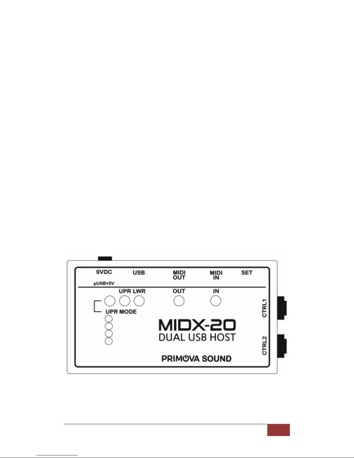
MIDX-20 DUAL USB Host
DESCRIPTION
The MIDX-20 unit has two USB Host ports (USB A sockets), a MIDI IN and a MIDI
OUT (both 5 pin MIDI) port, plus two controller jacks for generating MIDI from
external expression pedals or dual foot switches.
There are various programmable MIDI routing possibilities between the connectors.
A USB MIDI (foot) controller may control a USB device as well as other 5-pin MIDI
equipment.
Another routing possibility is when a 5-pin MIDI (foot) controller controls up to two
USB devices (see separate chapter for full description of the routing capabilities).
When connecting a guitar synthesizer with Guitar-to-MIDI conversion an external
synthesizer can be used for playback.
The unit also has an optional MIDI THRU/MERGE mode, sending 5-pin MIDI IN to the
5-pin MIDI OUT at the same time as other data from the USB devices is transmitted.
The two USB connectors are fully Roland/Boss compatible allowing any Roland/Boss
USB device to be connected for control or playback. Roland/Boss devices use a
vendor-specific USB MIDI communication protocol. This unit is compatible with the
following Roland/BOSS Guitar devices: Katana Amplifiers, GT-10, GT-100, GT-001,
VG-99, GR-55, GP-10 and SY-300.
Both USB connectors recognize Fender Mustang™ Amplifiers allowing the amps to
be controlled using MIDI commands (see the Mustang MIDI implementation chart
elsewhere in this manual).
Any MIDI class compliant USB device may be used with the unit, such as Fishman
TriplePlay, KMM SoftStep2, Logidy UMI3 USB MIDI Foot Controller, etc.
The MIDI USB Host is powered by a regulated 8-12V (center negative) mains adaptor
(not supplied) or a 5V Mini USB cable via a phone charger (not supplied).
Important:
- The MIDX-20 does NOT support USB Hubs.
- Powering the unit using a Mini USB cable directly connected to a Personal
Computer works, but is not recommended as digital noise may be
introduced.
- The unit can deliver a current up to 1.0 Amp assuming the power supply
(pedal board adapter or Mini USB adapter) is rated at that level.
MIDX-20 User’s Manual
4
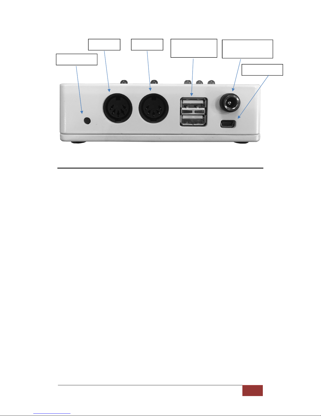
CONNECTORS
MIDIINANDMIDIOUT5-PINCONNECTORS
The two 5-pin MIDI connectors allow for connection of ‘classic’ MIDI devices in the
communication stream. The unit provides an optional MERGE/MIDI THRU feature
(enabled with the SET button), which will forward any incoming MIDI message from
the MIDI IN 5-pin connector directly to the MIDI OUT 5-pin connector. If there’s a
collision between USB messages from the USB device with messages from MIDI IN,
the message that started first gets priority to complete before the other streams are
allowed to pass through.
USBCONNECTORS
The MIDX-20 USB Host connectors allow communication with two Roland/BOSS
devices, Mustang™ Amplifiers, or any other class compliant MIDI devices. The
connector is of ‘stacked’ type with an upper and a lower USB slot.
The lower connector (LWR) is intended for a device controlled either by the upper
(UPR) connector or via 5-pin MIDI, and cannot be reconfigured.
The upper connector (UPR) is configurable and may be programmed for a second
device controlled by 5-pin MIDI or may be configured for a USB Foot controller.
MIDI IN MIDI OUT USB Connectors
(LWR and UPR)
8V – 12VDC
(center negative)
Mini USB 5V)
SET Button

MIDX-20 User’s Manual
5
POWERCONNECTORS
The MIDX-20 can be powered by:
1. Normal DC pedal board adapter (not included) 250mA – 2.0A (8V - 12V DC,
center pin negative). If the wrong polarity is used the unit will not be harmed,
but it will not work.
2. Mini USB cable (5V DC) from a phone charger (not included).
When connected to most devices the current draw by USB is negligible however the
LEDs and microcontroller circuitry require a few milliamps. The unit can deliver a
current up to 1.0 Amp assuming the power supply (pedal board adapter or Mini USB
adapter) is rated at that level.
PHYSICALDIMENSIONS
Dimensions 120 x 65 x 35 mm (max)
Weight 200g

MIDX-20 User’s Manual
6
CONTROLLERJACKS1&2
Each of the jacks allows you to connect either a Roland EV-5
expression pedal, a Roland FS-6, or Roland FS-7 compatible
dual foot switch. The expression pedals or foot switches will
be continuously monitored and converted to MIDI control
commands.
EXPRESSION PEDALS (ANALOG CONTROL)
Expression pedals compatible with MIDX-20 require a
10 kOhm potentiometer. The stereo plug TIP is
connected to the center tap of the potentiometer
(Output), the SLEEVE is connected to one end of the
potentiometer (Ground) and the RING (Input) is
connected to the other end of the potentiometer. At
heel-down position the lowest resistance should be
obtained between Tip (Output) and Sleeve (Ground)
Recommended expression pedals:
Roland EV-5, EV-7, Boss FV-500L
DUAL FOOT SWITCHES (ON/OFF CONTROL OR PROGRAM CHANGE)
Dual footswitches compatible with MIDX-20 require:
- One switch to short the TIP to SLEEVE when pressed.
- The other switch short the RING to SLEEVE when pressed.
The switches must be of MOMENTARY type (or the switch unit
must be configured to MOMENTARY mode).
Recommended switches:
Boss FS-6 and Boss FS-7
IMPORTANT NOTE:
For FS-7 use these settings: Polarity = II (RIGHT), Mode = FS-5U Momentary.
For FS-6 set both switches: Polarity = RIGHT, Mode = FS-5U Momentary.
MIDX-20 User’s Manual
7
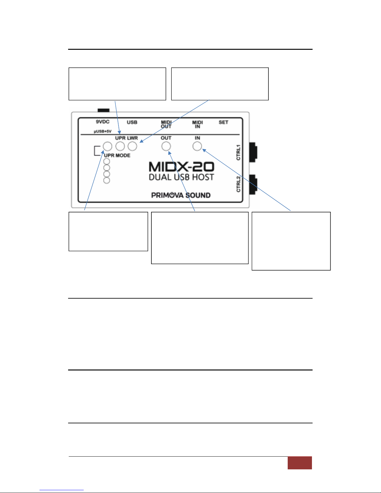
STATUSLEDS
In normal operation the LED’s show the following information.
FenderMustang™Bridge
MIDX-20 contains special software that allows control of one or two Fender
Mustang™ Amplifiers using regular MIDI commands.
You may control the Mustang™ by using an external MIDI controller connected to
the MIDX-20 and/or by using expression pedals/foot switches connected to the
CTRL1 and CTRL2 jacks.
IMPORTANT NOTE:
If you connect a Mustang™ to the upper USB connector the MIDX-20 need to be in
“DEVICE IN/OUT” mode (the leftmost LED showing RED) for proper operation.
If you connect a Mustang™ to the lower USB connector all of the Upper USB Modes
may be used.
Status of upper USB connector
Yellow – USB Disconnected
Green – Connected OK
Red – Connection Failed
Status of lower USB connector
Yellow – USB Disconnected
Green – Connected OK
Red – Connection Failed
Upper USB mode
Not lit – DEVICE OUT
Red – DEVICE IN/OUT
GREEN – CONTROLLER IN
YELLOW – CONTROLLER IN/OUT
5-PIN MIDI OUT TRAFFIC
Blinks when sending data.
- Normal mode: LED is normally off but
turns on when data is transmitted.
- MERGE/MIDI THRU mode: LED is
normally on but turns off when data is
transmitted.
5-PIN MIDI IN TRAFFIC
Blinks when receiving data.
- Normal mode: LED is normally
off but turns on when data is
received.
- MERGE/MIDI THRU mode: LED
is normally on but turns off
when data is received.

MIDX-20 User’s Manual
8
FenderMustang™Bridge-MIDIImplementation
PC#00 - PC#nn - Change Amplifier Patch Number (# of available patches may vary)
Miscellaneous CC’s
Tuner Toggle = CC#20 (0-63 Tuner OFF, 64-127 Tuner ON)
All FX Bypass = CC#22 (0-63 All effects OFF, 64-127 All effects ON)
Stomp CC’s
Bypass = CC#23 (0-63 effect OFF, 64-127 effect ON)
CC# 28 Stomp Effect CC# 29 CC# 30 CC# 31 CC# 32 CC# 33
None = 0 - - - - -
Overdrive = 1 Level Gain Low Mid High
Wah = 2 Mix Frequency Heel Freq Toe Freq High Q (0-1)
Touch Wah = 3 Mix Sensitivity Heel Freq Toe Freq High Q (0-1)
Fuzz = 4 Level Gain Octave Low High
(V1) Fuzz Touch Wah = 5 Level Gain Sensitivity Octave Peak
Simple Comp = 6 Type - - - -
Compressor = 7 Level Threshold Ratio Attack Time Release Time
(V2) Ranger Boost = 8 Level Gain Lo-cut Bright -
(V2) Green Box = 9 Level Gain Tone Blend -
(V2) Orange Box = 10 Level Dist Tone - -
(V2) Black Box = 11 Level Dist Filter - -
(V2) Big Fuzz = 12 Level Tone Sustain - -
Modulation CC’s
Bypass = CC#24 (0-63 effect OFF, 64-127 effect ON)
CC# 38 Mod Effect CC# 39 CC# 40 CC# 41 CC# 42 CC# 43
None = 0 - - - - -
Sine Chorus = 1 Level Rate Depth Average Delay LR Phase
Triangle Chorus =2 Level Rate Depth Average Delay LR Phase
Sine Flanger = 3 Level Rate Depth Feedback LR Phase
Triangle Flanger = 4 Level Rate Depth Feedback LR Phase
Vibratone = 5 Level Rotor Speed Depth Feedback LR Phase
Vintage Tremolo = 6 Level Rate Duty Cycle Attack Time Release Time
Sine Tremolo = 7 Level Rate Duty Cycle LFO Clipping Tri Shaping
Ring Modulator = 8 Level Frequency Depth LFO Shape LFO Phase
Step Filter = 9 Level Rate Resonance Min Freq Max Freq
Phaser = 10 Level Rate Depth Feedback LFO Shape
Pitch Shift = 11 Level Rate Detune Feedback Pre Delay
(V2) Wah = 12 Mix Frequency Heel Freq Toe Freq High Q(0-1)
(V2) Touch Wah = 13 Mix Sensitivity Min Freq Max Freq High Q (0-1)
(V2) Diatonic Pitch Shift = 14 Mix Pitch (0-21) Key (0-11) Scale (0-8) Tone
Delay CC’s
Bypass = CC#25 (0-63 effect OFF, 64-127 effect ON)
CC# 48 Delay Effect CC# 49 CC# 50 CC# 51 CC# 52 CC# 53 CC# 54
None = 0 - - - - - -
Mono Delay = 1 Level Delay Time Feedback Brightness Attenuation -
Mono Echo Delay =2 Level Delay Time Feedback Frequency Resonance Input Level
Stereo Echo Filter = 3 Level Delay Time Feedback Frequency Resonance Input Level
Multitap Delay = 4 Level Delay Time Feedback Brightness Mode -
Ping Pong Delay = 5 Level Delay Time Feedback Brightness Stereo -
Ducking Delay = 6 Level Delay Time Feedback Release Threshold Reverse Delay = 7 Level Delay Time FFdbk RFdbk Tone -
Tape Delay = 8 Level Delay Time Feedback Flutter Brightness Stereo
Stereo Tape Delay Level Delay Time Feedback Flutter Separation Brightness

MIDX-20 User’s Manual 9
Reverb CC’s
Bypass = CC#26 (0-63 effect OFF, 64-127 effect ON)
CC# 58 Reverb Effect CC# 59 CC# 60 CC# 61 CC# 62 CC# 63
None = 0 - - - - Small Hall = 1 Level Decay Dwell Diffusion Tone
Large Hall = 2 Level Decay Dwell Diffusion Tone
Small Room = 3 Level Decay Dwell Diffusion Tone
Large Room = 4 Level Decay Dwell Diffusion Tone
Small Plate = 5 Level Decay Dwell Diffusion Tone
Large Plate = 6 Level Decay Dwell Diffusion Tone
Ambient = 7 Level Decay Dwell Diffusion Tone
Arena = 8 Level Decay Dwell Diffusion Tone
63 Fender Spring = 9 Level Decay Dwell Diffusion Tone
65 Fender Spring = 10 Level Decay Dwell Diffusion Tone
Amp CC’s
Bypass = CC#27 (0-63 effect OFF, 64-127 effect ON) Noise Gate
0-63 Off
64-127 On
CC# 68 Amp Type
CC# 69 CC# 70 CC# 71 CC# 72 CC# 73 CC# 74 CC# 75 CC# 76 CC# 77 CC# 78 CC# 79 CC#90 CC# 91 CC# 92
None = 0 - - - - - - - - - - - - - -
Fender ’57 Deluxe = 1 Ga in Ch. Volume Treble Middle Bass Sag (0-2) Bias Noise Gate (0-4) Cab (0-12) - NG Thresh (0-9) NG Depth -
Fender’ 59 Bassman = 2 Ga in Ch. Volume Treble Middle Bass Sag (0-2) Bias Noise Gate (0-4) Cab (0-12) Presence Blend NG Thresh (0-9) NG Depth -
Fender ’57 Champ = 3 G ain Ch. Volume Treble Middle Bass Sag (0-2) Bias Noise Gate (0-4) Cab (0-12) - NG Thresh (0-9) NG Depth -
Fender ’65 Deluze Reverb = 4 Gain Ch. Volume Treble Middle Bass Sag (0-2) Bias Noise Gate (0-4) Cab (0-12) - NG Thresh (0-9) NG Depth -
Fender ’65 Princeton = 5 G ain Ch. Volume Treble Middle Bass Sag (0-2) Bias Noise Gate (0-4) Cab (0-12) - NG Thresh (0-9) NG Depth -
Fender ’65 Twin Reverb = 6 Gain Ch. Volume Treble Middle Bass Sag (0-2) Bias Noise Gate (0-4) Cab (0-12) - NG Thresh (0-9) NG Depth Bright Sw.
Fender Supersonic (Burn) =7 Gain Ch. Volume Treble Middle Bass Sag (0-2) Bias Noise Gate (0-4) Cab (0- 12) G ain2 Master Vol NG Thresh (0-9) NG Depth -
British ‘60s = 8 Gain Ch. Volume Treble Middle Bass Sag (0-2) Bias Noise Gate (0-4) Cab (0-12) Cut Master Vol NG Thresh (0-9) NG Depth Bright Sw.
British ‘70s = 9 Gain Ch. Volume Treble Middle Bass Sag (0-2) Bias Noise Gate (0-4) Cab (0-12) Presence Blend NG Thresh (0-9) NG Depth -
British ‘80s= 10 Gain Ch. Volume Treble M iddle Ba ss Sag (0-2) Bias Noise Gate (0-4) Cab (0-12) Presence Ma ster Vol NG Thresh (0-9) NG Depth -
American ‘90s = 11 Gain Ch. Volume Treble Middle Bass Sag (0-2) Bias Noise Gate (0-4) Cab (0-12) Presence Master Vol NG Thresh (0-9) NG Depth -
Metal 2000 = 12 Gain Ch. Volume Treble Middle Bass Sag (0-2) Bias Noise Gate (0-4) Cab (0-12) Presence Mas ter Vol NG Thresh (0-9) NG Depth -
(V2) Studio Preamp = 13 Gain Ch. Volume Treble Middle Bass - - Noise Gate ( 0-4) Cab (0-12) - - NG Thres h (0-9) NG Depth -
(V2) Fender ’57 Twin = 14 Gain Ch. Volume Treble Middle Bass Sag (0-2) Bias Noise Gate (0-4) Cab (0-12) Presence NG Thresh (0-9) NG Depth -
(V2) Sixties Thrift = 15 Gain Ch. Volume Treble Middle Bass Sag (0-2) Bias Noise Gate (0-4) Cab (0- 12) - - NG Thresh (0-9) NG Depth -
(V2) British Watts = 16 G ain Ch. Volume Treble Middle Bass Sag (0-2) Bias Noise Gate (0-4) Cab (0-12) Presence Master Vol NG Thresh (0-9) NG Depth -
(V2) British Colour = 17 G ain Ch. Volume Treble Middle Bass Sag (0-2) Bias Noise Gate (0-4) Cab (0-12) - Master Vol NG Thresh (0-9) NG Depth -

MIDX-20 User’s Manual
10 10
SETTINGUPTHEUNIT
Use the small pushbutton to configure the MIDX-20. If you cannot reach the pushbutton
with your finger, use a tooth pick or a small screw driver.
FAST CLICK: Turn MIDI THRU/MERGE mode ON/OFF
SHORT x 1
If you click the button quickly (< 1 second) the MIDI MERGE mode will toggle on or off.
The status is shown on the MIDI IN and MIDI OUT LEDs. If they are off MERGE is OFF, if
they show a GREEN light then MERGE is ON.
LONG HOLD: Change MODE of the UPPER USB CONNECTOR
LONG x 1
If you hold the button in for more than 2 seconds the UPR MODE will change.
The status is shown on the UPR MODE LED:
LED is OFF – Mode for two USB devices, UPR is only sending data.
LED is RED – Mode for two USB devices, UPR is bidirectional.
LED is GREEN – Mode for a USB Controller on UPR, UPR is only receiving data.
LED is YELLOW – Mode for a USB Controller on UPR, UPR is bidirectional.
NOTE: For a full description of modes see chapter ‘MIDX-20 MODES / MIDI DATA FLOW’
CLICK 5 TIMES: Run the Setup Wizard
SHORT x 5
If you quickly press the button 5 times the unit will go into a ‘Setup Wizard’ mode.

MIDX-20 User’s Manual
11 11
While in Setup Wizard mode the following button press patterns can be used at any time:
x 1 ‘EDIT’ - Increment value at the current Wizard step.
After reaching maximum value it will resume at the minimum value.
x 2 ‘NEXT SETTING’ - Move forward to the next setting of the Wizard.
x 3 ‘PREVIOUS SETIING’ - Move back to the previous setting of the Wizard.
x 5 ‘SAVE’ - Immediately store settings and exit the Wizard.
All settings following the current step will be as they were before you
started the Wizard.
“Ones” and “Tens” – Numbers 00-99 are setup in two steps. First you set the “Tens” part
and then the “Ones” part. Example: For the number 68, Tens=’6’ and Ones=’8’.
68
Description of foot switch modes:
Send CC# Latched The first time the foot switch is pressed, the value 127 will be sent to the control. The next
time 0 will be sent, and so on in a toggling/latched fashion.
The next Wizard step will setup the Control number used.
Send CC#
Momentary
When foot switch is held down, 127 will be sent to the control, and when released 0 will be
sent. The next Wizard step will setup the Control number used.
Send fixed PC# When the foot switch is pressed a fixed Program Change (PC) number will be sent. The next
step will set up what fixed number to use.
Decrement PC# When the foot switch is pressed the current Program Change number will be decremented
and sent. The next step will set up the STARTING (power-on) program number.
Increment PC# When the foot switch is pressed the current Program number will be incremented and sent.
The next step will setup the STARTING (power-on) program number.
Note: if one FS is used for decrement and the other FS is used for increment, the decrement
STARTING number is used for both switches.
Send START This will send out a START command. The next two Wizard steps have no meaning.
Send CONTINUE This will send out a CONTINUE command. The next two Wizard steps have no meaning.
Send STOP This will send out a CONTINUE command. The next two Wizard steps have no meaning.
Ones
Tens

MIDX-20 User’s Manual
12 12
STEP 1 - Set CTRL1 MIDI Channel
x 1
The Channel number
will increment by 1, After Channel
16 it will resume at Channel 1.
x 2
When the preferred
channel is selected, double-click
the button to advance to the next
step of the Wizard.
STEP 2 - Set CTRL2 MIDI Channel
x 1
The Channel number
will increment by 1. After Channel
16 it will resume at Channel 1.
x 2
When the preferred
channel is selected, double-click
the button to advance to the next
step of the Wizard.
STEP 3 - Set Mustang™ MIDI Channel
x 1
The Channel number
will increment by 1. After Channel
16 it will restart at Channel 1.
x 2
When the preferred
channel is selected, double-click
the button to advance to the next
step of the Wizard.
UPR MODE
UPR LWR
MIDI OUT
MIDI IN
Meaning
RED FLASH
- - - -
Channel 1
RED FLASH
- - -
GREEN
Channel 2
RED FLASH
- -
GREEN
Channel 3
RED FLASH
- -
GREEN
GREEN
Channel 4
RED FLASH
-
GREEN
- Channel 5
RED FLASH
-
GREEN
-
GREEN
Channel 6
RED FLASH
-
GREEN
GREEN
-
Channel 7
RED FLASH
-
GREEN
GREEN
GREEN
Channel 8
RED FLASH
GREEN
- - -
Channel 9
RED FLASH
GREEN
- -
GREEN
Channel 10
RED FLASH
GREEN
-
GREEN
-
Channel 11
RED FLASH
GREEN
-
GREEN
GREEN
Channel 12
RED FLASH
GREEN
GREEN
- -
Channel 13
RED FLASH
GREEN
GREEN
-
GREEN
Channel 14
RED FLASH
GREEN
GREEN
GREEN
Channel 15
RED FLASH
GREEN
GREEN
GREEN
GREEN
Channel 16
UPR MODE
UPR LWR
MIDI OUT
MIDI IN
Meaning
YELLOW FLASH
- - - - Channel 1
YELLOW FLASH
- - - GREEN
Channel 2
YELLOW FLASH
- - GREEN
Channel 3
YELLOW FLASH
- - GREEN
GREEN
Channel 4
YELLOW FLASH
- GREEN
- Channel 5
YELLOW FLASH
- GREEN
-
GREEN
Channel 6
YELLOW FLASH
- GREEN
GREEN
-
Channel 7
YELLOW FLASH
- GREEN
GREEN
GREEN
Channel 8
YELLOW FLASH
GREEN
- - -
Channel 9
YELLOW FLASH
GREEN
- -
GREEN
Channel 10
YELLOW FLASH
GREEN
-
GREEN
-
Channel 11
YELLOW FLASH
GREEN
-
GREEN
GREEN
Channel 12
YELLOW FLASH
GREEN
GREEN
- -
Channel
13
YELLOW FLASH
GREEN
GREEN
-
GREEN
Channel 14
YELLOW FLASH
GREEN
GREEN
GREEN
Channel 15
YELLOW FLASH
GREEN
GREEN
GREEN
GREEN
Channel 16
UPR MODE
UPR LWR
MIDI OUT
MIDI IN
Meaning
GREEN FLASH
- - - - Channel 1
GREEN FLASH
- - - GREEN
Channel 2
GREEN
FLASH - - GREEN
Channel 3
GREEN FLASH
- - GREEN
GREEN
Channel 4
GREEN FLASH
- GREEN
- Channel 5
GREEN FLASH
- GREEN
-
GREEN
Channel 6
GREEN FLASH
- GREEN
GREEN
-
Channel 7
GREEN FLASH
- GREEN
GREEN
GREEN
Channel 8
GREEN FLASH
GREEN
- - -
Channel 9
GREEN FLASH
GREEN
- -
GREEN
Channel 10
GREEN FLASH
GREEN
-
GREEN
-
Channel 11
GREEN FLASH
GREEN
-
GREEN
GREEN
Channel 12
GREEN FLASH
GREEN
GREEN
- -
Channel 13
GREEN FLASH
GREEN
GREEN
-
GREEN
Channel 14
GREEN FLASH
GREEN
GREEN
GREEN
Channel 15
GREEN FLASH
GREEN
GREEN
GREEN
GREEN
Channel 16

MIDX-20 User’s Manual
13 13
The following steps (4-11) show how to configure the CTRL1 jack for expression pedals
or dual footswitches. Steps 12-19 for configuring CTRL2 properties are identical. To
save pages in this document the CTRL2 steps are not included.
STEP 4 - Set CTRL1 EXPR. PEDAL Control Number (CC#) 1
st
Digit (Tens)
x 1
Increment the “Tens” digit
of the CC#.
x 2
Advance to the next step
of the Wizard.
STEP 5 - Set CTRL1 EXPR. PEDAL Control Number (CC#) 2nd Digit (Ones)
x 1
Increment the “Ones” digit
of the CC#.
x 2
Advance to the next step
of the Wizard.
Note:
If CC# is 00 then the Expression Pedal is turned OFF
UPR MODE
UPR LWR
MIDI OUT
MIDI IN
Digit
YELLOW
- - - - 0
YELLOW
-
- - GREEN
1
YELLOW
-
- GREEN
- 2
YELLOW
-
- GREEN
GREEN
3
YELLOW
-
GREEN
- - 4
YELLOW
-
GREEN
-
GREEN
5
YELLOW
-
GREEN
GREEN
- 6
YELLOW
-
GREEN
GREEN
GREEN
7
YELLOW
GREEN
- - - 8
YELLOW
GREEN
- - GREEN
9
UPR MODE
UPR LWR
MIDI OUT
MIDI IN
Digit
YELLOW
FLASH - - - - 0
YELLOW
FLASH - - - GREEN
1
YELLOW
FLASH - - GREEN
- 2
YELLOW
FLASH - - GREEN
GREEN
3
YELLOW
FLASH - GREEN
- - 4
YELLOW
FLASH - GREEN
-
GREEN
5
YELLOW
FLASH - GREEN
GREEN
- 6
YELLOW
FLASH - GREEN
GREEN
GREEN
7
YELLOW
FLASH GREEN
- - - 8
YELLOW
FLASH GREEN
- - GREEN
9

MIDX-20 User’s Manual
14 14
STEP 6 - Set Mode of CTRL1 “TIP” Foot switch
x 1
The Mode will
increment. After the last
mode it will resume at the
first.
x 2
Advance to
the next step of the Wizard.
STEP 7 - Set CTRL1 “TIP” Foot switch 1st Digit (Tens)
This number (Tens) combined with the next step (Ones) is used by the Mode you have selected. If the
mode is CC# (latched or momentary) it’s the CC# to use. If it is PC# fixed then it’s the PC# to use. If it’s PC#
decrement/increment, it’s the starting PC# when the unit is started up. For START, CONTINUE and STOP
this value has no meaning.
x 1
Increment the “Tens” digit.
x 2
Advance to the next step of the
Wizard.
STEP 8 - Set CTRL1 “TIP” Foot switch 2nd Digit (Ones
x 1
Increment the “Ones” digit.
x 2
Advance to the next step of the
Wizard.
Notes:
BOSS FS-7: If the stereo plug is connected to jack B, then FS-B is “TIP” and FS-A
is “RING”. If the stereo plug is connected to jack A, the FS-A is “TIP” and ‘B’ is
not available. BOSS FS-6: If the stereo plug is connected to jack A&B, then FS-B
is “TIP” and FS-A is “RING”. If CC# mode and CC#=0 then the foot switch is off.
UPR MODE
UPR LWR
MIDI OUT
MIDI IN
Digit
RED FLASH
RED FLASH
- - - Send CC# Latched
RED FLASH
RED FLASH
- - GREEN
Send CC# Momentary
RED FLASH
RED FLASH
- GREEN
-
Send fixed PC#
RED FLASH
RED FLASH
- GREEN
GREEN
Decrement PC#
RED FLASH
RED FLASH
GREEN
- -
Increment PC#
RED FLASH
RED FLASH
GREEN
-
GREEN
Send START
RED FLASH
RED FLASH
GREEN
GREEN
-
Send CONTINUE
RED FLASH
RED FLASH
GREEN
GREEN
GREEN
Send STOP
UPR MODE
UPR LWR
MIDI OUT
MIDI IN
Digit
RED - - - - 0
RED - - - GREEN
1
RED - - GREEN
- 2
RED - - GREEN
GREEN
3
RED - GREEN
- - 4
RED - GREEN
-
GREEN
5
RED - GREEN
GREEN
- 6
RED - GREEN
GREEN
GREEN
7
RED GREEN
- - - 8
RED GREEN
- - GREEN
9
UPR MODE
UPR LWR
MIDI OUT
MIDI IN
Digit
RED FLASH
-
- - - 0
RED FLASH
-
- - GREEN
1
RED FLASH
-
- GREEN
- 2
RED FLASH
-
- GREEN
GREEN
3
RED FLASH
-
GREEN
- - 4
RED FLASH
-
GREEN
-
GREEN
5
RED FLASH
-
GREEN
GREEN
- 6
RED FLASH
-
GREEN
GREEN
GREEN
7
RED FLASH
GREEN
- - - 8
RED FLASH
GREEN
- - GREEN
9

MIDX-20 User’s Manual
15 15
STEP 9 - Set Mode of CTRL1 “RING” Foot switch
x 1
The Mode
will increment. After
the last mode it will
resume at the first.
x 2
Advance
to the next step of the
Wizard.
STEP 10 - Set CTRL1 “RING” Foot switch 1st Digit (Tens)
This number (Tens) combined with the next step (Ones) is used by the Mode you have selected. If the
mode is CC# (latched or momentary) it’s the CC# to use. If it is PC# fixed then it’s the PC# to use. If it’s PC#
decrement/increment, it’s the starting PC# when the unit is started up. For START, CONTINUE and STOP
this value has no meaning.
x 1
Increment the “Tens” digit.
x 2
Advance to the next step of the
Wizard.
STEP 11 - Set CTRL1 “RING” Foot switch 2nd Digit (Ones)
x 1
Increment the “Ones” digit.
x 2
Advance to the next step of
the Wizard.
NOTE: AT THIS POINT THE WIZARD WILL CONTINUE WITH STEPS 12-19 TO CONFIGURE
CTRL2 JACK PROPERTIES. THESE STEPS ARE IDENTICAL TO STEPS 4-11.
UPR MODE
UPR LWR
MIDI OUT
MIDI IN
Digit
GREEN FLASH
GREEN FLASH
- - - Send CC# Latched
GREEN FLASH
GREEN FLASH
- - GREEN
Send CC#
Momentary
GREEN FLASH
GREEN FLASH
- GREEN
-
Send fixed PC#
GREEN FLASH
GREEN FLASH
- GREEN
GREEN
Decrement PC#
GREEN FLASH
GREEN FLASH
GREEN
- -
Increment PC#
GREEN FLASH
GREEN FLASH
GREEN
-
GREEN
Send START
GREEN FLASH
GREEN FLASH
GREEN
GREEN
-
Send
CONTINUE
GREEN FLASH
GREEN FLASH
GREEN
GREEN
GREEN
Send STOP
UPR MODE
UPR LWR
MIDI OUT
MIDI IN
Digit
GREEN
-
- - - 0
GREEN
-
- - GREEN
1
GREEN
-
- GREEN
- 2
GREEN
-
- GREEN
GREEN
3
GREEN
-
GREEN
- - 4
GREEN
-
GREEN
-
GREEN
5
GREEN
-
GREEN
GREEN
- 6
GREEN
-
GREEN
GREEN
GREEN
7
GREEN
GREEN
- - - 8
GREEN
GREEN
- - GREEN
9
UPR MODE
UPR LWR
MIDI OUT
MIDI IN
Digit
GREEN
FLASH - - - - 0
GREEN FLASH
-
- - GREEN
1
GREEN FLASH
-
- GREEN
- 2
GREEN FLASH
-
- GREEN
GREEN
3
GREEN FLASH
-
GREEN
- - 4
GREEN FLASH
-
GREEN
-
GREEN
5
GREEN FLASH
-
GREEN
GREEN
- 6
GREEN FLASH
-
GREEN
GREEN
GREEN
7
GREEN FLASH
GREEN
- - - 8
GREEN FLASH
GREEN
- - GREEN
9

MIDX-20 User’s Manual
16 16
MIDX-20CONNECTIONEXAMPLES
USB ‘UPR’ IS SET AS CTRL IN (or IN/OUT)
In this mode a USB foot controller plus external foot controllers and expression pedals
may control for instance a GP-10 and GR-55.
Guitar-to-MIDI from the GP-10 can be played back to a 5-Pin MIDI Synth.
USB ‘UPR’ IS SET AS DEV OUT (or IN/OUT)
In this mode the 5-PIN MIDI foot controller and the FS-7, EV-5s control three devices, GT001, GP-10 and GR-55.
Guitar-to-MIDI from the GP-10 can be played back to any 5-Pin MIDI Synth.

MIDX-20 User’s Manual
17 17
Another two-device example, controlling both a Mustang™ and a GP-10:

MIDX-20 User’s Manual
18 18
REAL-TIMEMESSAGES
MIDI Clock - When power is first applied, no input is defined as a master and all clock
messages from both inputs will be passed until one input is defined as a master. The
input to receive the most recent START command will become the clock master. That
input continues to be the clock master until another input satisfies the above condition.
Active Sensing - The first input to receive an active sensing message will become the
active sensing master. Active sensing messages from that input will be passed to the
output and any active sensing messages received at other inputs will be ignored. The
input will remain the active sensing master until no additional active sensing messages
are received at that input for a period of a few seconds. Then the other input has the
opportunity to become the active sensing master.
MIDX-20MODES/MIDIDATAFLOW
As there are three bidirectional MIDI connections (2xUSB + Standard MIDI) and two
controller jacks, the flow of data between the connectors can be configured in many
different ways. To cover most cases, four modes have been elected for the MIDX-20,
selected using the SET button. A LONG HOLD of the button will cycle through the four
modes and the current mode will show on the UPR MODE LED.
LED is OFF – Mode for two USB devices, UPR is only sending data.
LED is RED – Mode for two USB devices, UPR is bidirectional.
LED is GREEN – Mode for a USB Controller on UPR, UPR is only receiving data.
LED is YELLOW – Mode for a USB Controller on UPR, UPR is bidirectional.
Each of the four modes may also have MIDI THRU/MERGE ON or OFF rendering the total
number of possible configurations to eight. The following flow charts describes in detail
how the unit operates in these eight modes.
This symbol is used to indicate a merge of two or more MIDI data streams.
If there’s a collision between USB messages, the message started first gets priority to
complete before the other stream is allowed to pass through.
Note:
The MIDI MERGE mode allows for forwarding MIDI data and daisy-chaining several
devices (or MIDX-20 units) via the 5-Pin MIDI connections.
+

MIDX-20 User’s Manual
19 19
UPR IS ‘DEV OUT’ and MIDI THRU/MERGE is ‘OFF’
UPR IS ‘DEV OUT’ and MIDI THRU/MERGE is ‘ON’

MIDX-20 User’s Manual
20 20
UPR IS ‘DEV IN/OUT’ and MIDI THRU/MERGE is ‘OFF’
UPR IS ‘DEV IN/OUT’ and MIDI THRU/MERGE is ‘ON’

MIDX-20 User’s Manual
21 21
UPR IS ‘CTRL IN’ and MIDI THRU/MERGE is ‘OFF’
UPR IS ‘CTRL IN’ and MIDI THRU/MERGE is ‘ON’

MIDX-20 User’s Manual
22 22
UPR IS ‘CTRL IN/OUT’ and MIDI THRU/MERGE is ‘OFF’
UPR IS ‘CTRL IN/OUT’ and MIDI THRU/MERGE is ‘ON’

MIDX-20 User’s Manual
23 23
SETUPUSINGPCSOFTWARE
The MIDX-20 Assistant application allows you to configure the MIDX-20 using a PC
connected to the MIDX-20 via a standard USB to MIDI converter ‘cable’ such as Roland
UM-ONE.
For newer version of this manual or to download of the MIDX-20 Assistant, please visit
www.primovasound.com
FIRMWAREUPGRADES
Firmware upgrades are published at www.primovasound.com, along with the MIDX-20
Assistant PC-software required to upgrade your MIDX-20.
WARRANTY
PRIMOVA WARRANTS THE MIDX-20 PRODUCT FOR ONE YEAR. TWO YEARS IF INSIDE EU.
LIMITATION OF LIABILITY AND WARRANTY
NO WARRANTIES OF DAMAGES TO CONNECTED EQUIPMENT OR CABLES.
NO WARRANTIES IF UNSUITABLE VOLTAGE HAS BEEN APPLIED TO CONNECTORS.
PRIMOVA AB ONLY WARRANTS THE MIDX-20 UNIT ITSELF.
CONNECTING THE MIDX-20 UNIT OR THE MIDX-20 BOARD, TO COMPONENTS SUCH AS SYNTHESIZERS OR
COMPUTERS IS AT OWN RISK.
IN NO EVENT WILL PRIMOVA BE LIABLE FOR DIRECT, INDIRECT, SPECIAL, INCIDENTAL, OR CONSEQUENTIAL
DAMAGES ARISING OUT OF THE USE OR THE INABILITY TO USE THE MIDX-20 UNIT EVEN IF ADVISED OF
THE POSSIBILITY OF SUCH DAMAGES. IN PARTICULAR, PRIMOVA IS NOT RESPONSIBLE FOR ANY COSTS
INCLUDING BUT NOT LIMITED TO THOSE INCURRED AS A RESULT OF LOST PROFITS OR REVENUE, LOSS OF
USE OF THE MIDX-20 PRODUCT, LOSS OF DATA, THE COST OF SUBSTITUTING THE MIDX-20 UNIT, OR ANY
CLAIMS BY THIRD PARTIES.
© Copyright Primova AB Sweden 2016
PRIMOVA AB
Kurlandaallén 21
68151 Kristinehamn, Sweden
www.primovasound.com, email: sound@primova.se
Thanks to:
Steven Hirsch (Snhirsch) for assisting in developing and testing the MIDX-20 Mustang
MIDI Bridge, and Steve Conrad (Elantric) for valuable input and for maintaining the
V-Guitar forums www.vguitarforums.com
 Loading...