

PrimeVOLT V-3000N-V, PV-5000W-V, PV-5000W-HV Installation & Operation Manual

Ver. 1.0 (EN) NOV. 2017 Printed on Recycled Paper
SINGLE PHASE ON-GRID PV INVERTER
PV-3000N-V & PV-5000W-V & PV-5000W-HV
Installation & Operation Manual
1
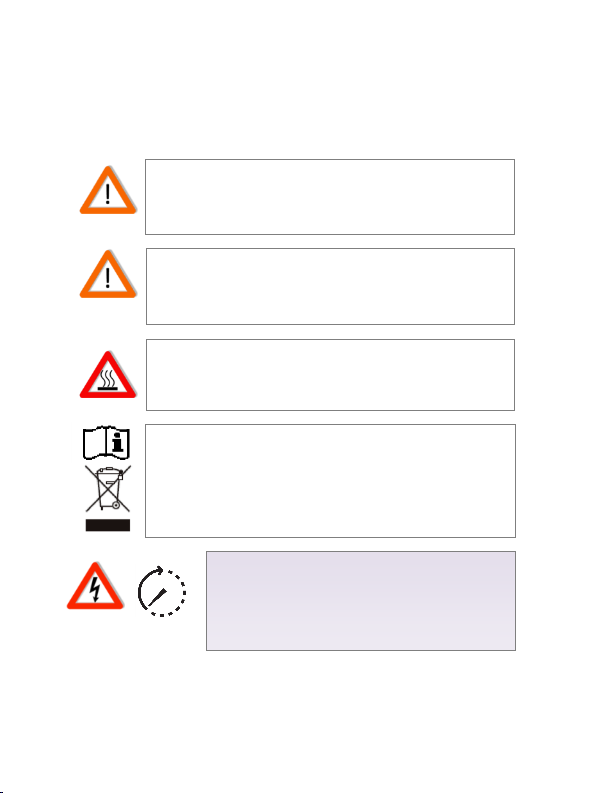
1. Safety Precautions
Before beginning your journey, please read the following safety instructions
carefully.
PV--V
Qualified Personnel ONLY!
Only Qualified technicians shall install or service unit(s) in
accordance with local wiring regulations.
PV Modules ONLY!
Designed for PV and solar power conversion only; do not use for
other DC sources or conversion purposes.
Hot Surface
Metallic parts of enclosure may be hot during operation.
Recycle
Do not throw this electronic device in a trash dumpster when
being disposed of. To minimize pollution of environment, please
consult your local service provider.
Danger!
High voltage inside inverter can cause Electric shock,
even when inverter is not operating. Wait for at least
45 minutes before opening the enclosure.
45 minutes
2
2. Contact Information
Asian Power Devices Inc.
(Trade mark: PrimeVOLT )
TEL: +886-2-2695-5388
FAX:+886-2-2693-1009
ADD: 11F., No.211, Nanyang St., Xizhi Dist.,New Taipei City 221, TAIWAN
Official Website: http://www.primevolt.com

3
3. Warranty Information
Warranty or liability will be void if damage caused by, but not limited to the
following:
1. Unauthorized opening of unit
2. Installation faults such as improper environment, wiring and applications
3. Working conditions beyond specified
4. Improper operation of unit
5. Violation of safety instructions in this manual
6. Damage during transportation
7. Any internal modifications
8. Replacing or installation of unauthorized software
9. Unforeseen calamity or force majeure

4
Table of Contents
1. Safety Precautions .................................................................................................. 1
2. Contact Information ............................................................................................... 2
3. Warranty Information ............................................................................................. 3
4. PV System ............................................................................................................... 5
5. Product Overview ................................................................................................... 6
6. Installation ............................................................................................................ 10
6.1 Assembly Chart .................................................................................................. 12
6.2 Choosing Proper Installation Site ....................................................................... 13
6.3 Mounting Properly ............................................................................................. 14
6.4 Mounting Procedure .......................................................................................... 15
6.5 Wire Connections ............................................................................................... 17
6.6 Ready to Start .................................................................................................... 27
7. Operation (S-Series) .............................................................................................. 29
7.1 Overview ............................................................................................................ 29
7.2 Setting Clock ...................................................................................................... 30
7.3 Status LED .......................................................................................................... 32
7.4 Frames ............................................................................................................... 32
7.5 Network and Internet......................................................................................... 36
7.6 Browsing Inverter Web Page ............................................................................. 37
7.7 Using USB ........................................................................................................... 42
8. Operation (ES-Series) ............................................................................................ 44
9. RS485 .................................................................................................................... 49
9.1 About RS485 ....................................................................................................... 49
9.2 Connecting RS485 .............................................................................................. 49
10. Connecting to Ripple Control Receiver (RCR) ..................................................... 51
11. Maintenance ....................................................................................................... 53
12. Troubleshooting .................................................................................................. 54
13. Specifications ...................................................................................................... 55
14. Addendum .......................................................................................................... 57
5
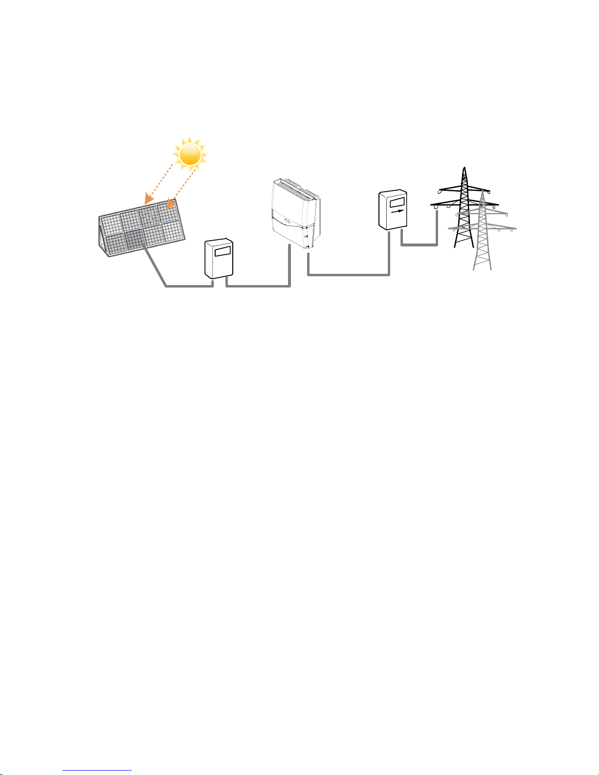
4. PV System
DC Switchboard
PV Generator
AC Switchboard
Public Grid
PV Inverter
A typical PV system contains:
1. PV Generator: Receive sunlight and generate DC power
2. DC Switchboard: Links between PV panels and PV inverter, include of DC
switch and surge protection
3. Inverter's DC Switch: PV Inverter with DC Switch
4. PV Inverter: Converts DC power by PV panels to AC output power for public
grid
5. AC Switchboard: Links between PV inverter and public grid
6. Public Grid: Provides utility for homes
6
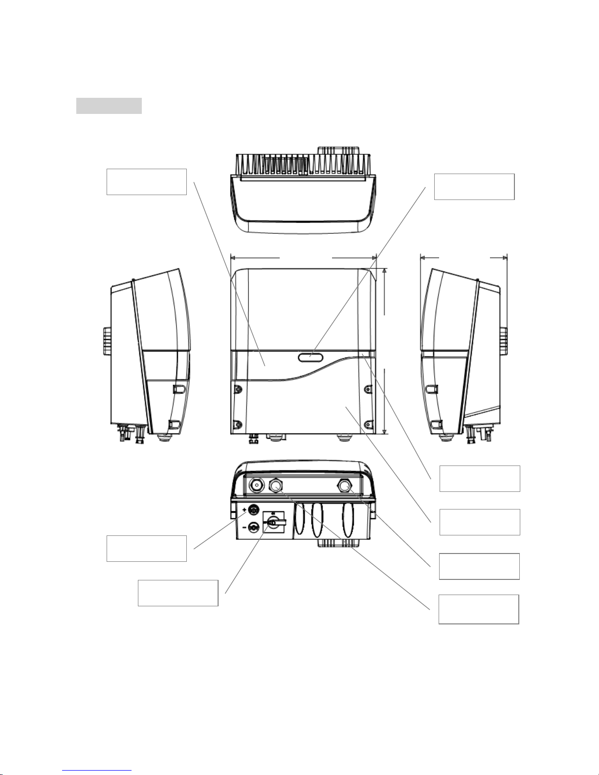
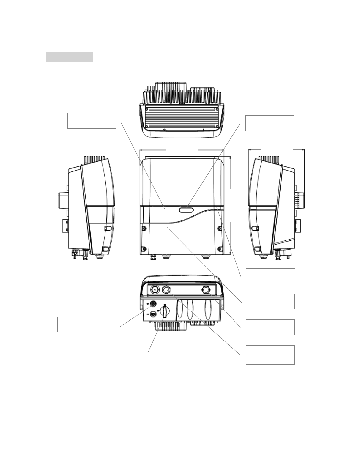
5. Product Overview
PV-3000N-V
Status LED
Front Cover
AC Cable Gland
Signal Cable
Gland
DC Switch
DC (PV) Inputs
Display LCD
Button & LED
330(mm)
196(mm)
375(mm)

7
PV-5000W-V
Button & LED
Display LCD
Status LED
Front Cover
AC Cable Gland
Signal Cable
Gland
DC Switch
DC (PV) Inputs
418(mm)
190(mm)
485(mm)
8
PV-5000W-HV
Signal Cable
Gland
Button & LED
AC Cable Gland
Status LED
Display LCD
DC (PV) Inputs
DC Switch
Front Cover
328(mm)
218(mm)
383(mm)

9
Product Labels
10
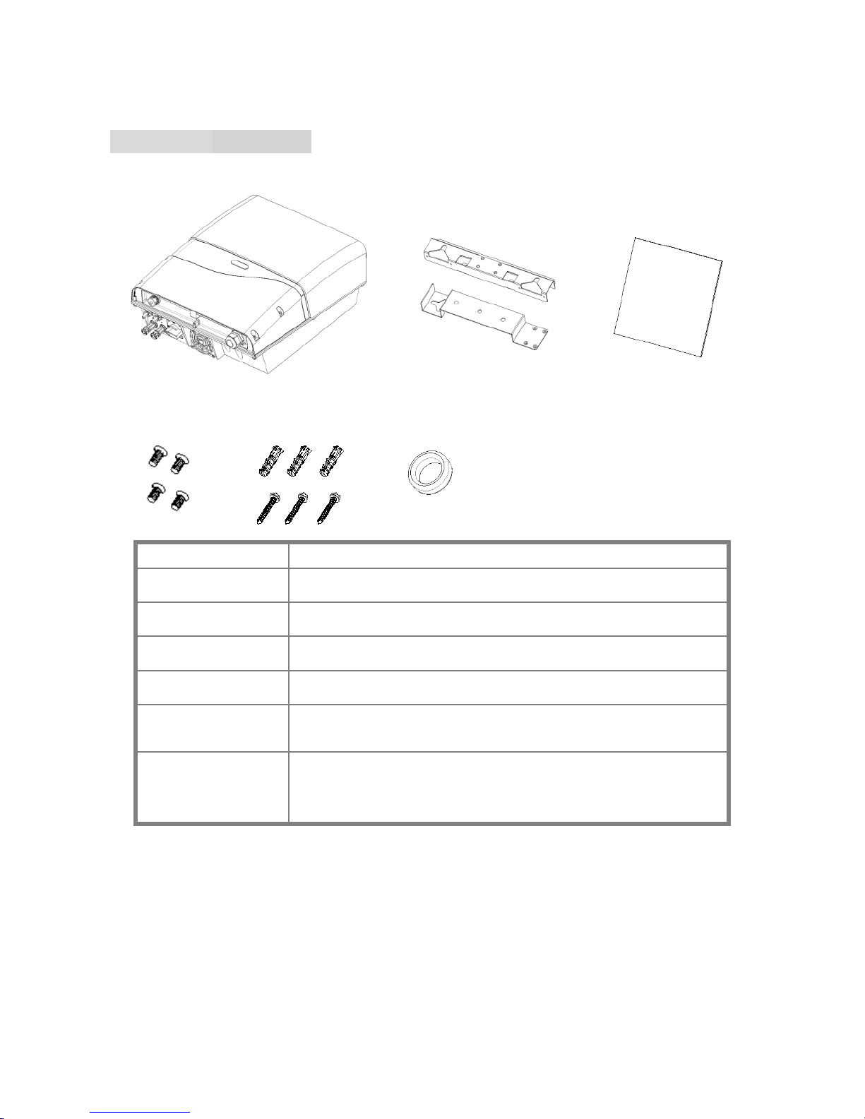
6. Installation
PV-3000N-V/PV-5000W-V
Item
Description
Ⓐ
Inverter
Ⓑ
Mounting bracket kit
Ⓒ
User manual
Ⓓ
M4 flat screws × 8, used for mounting bracket
Ⓔ
Plastic anchors & screws × 3. Used to install
mounting bracket on wall
Ⓕ
EMI core(s) for Ethernet cable(s)
PV-3000N-V: Circular EMI cores × 2
PV-5000W-V: Clip-on EMI core × 1
Ⓐ
Ⓑ Ⓒ Ⓓ Ⓔ Ⓕ
*
11
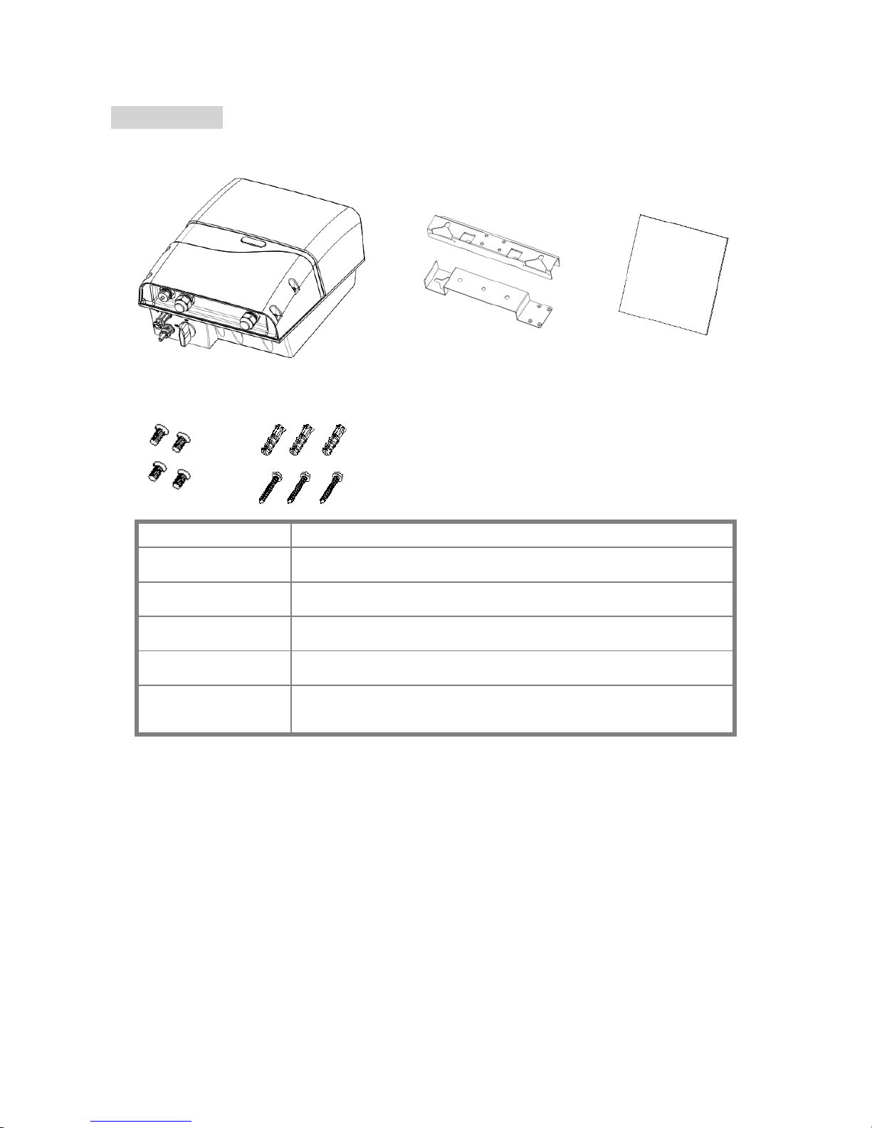
PV-5000W-HV
Item
Description
Ⓐ
Inverter
Ⓑ
Mounting bracket kit
Ⓒ
User manual
Ⓓ
M4 flat screws × 8, used for mounting bracket
Ⓔ
Plastic anchors & screws × 3. Used to install
mounting bracket on wall
Ⓐ
Ⓑ
Ⓒ
Ⓓ
Ⓔ
12
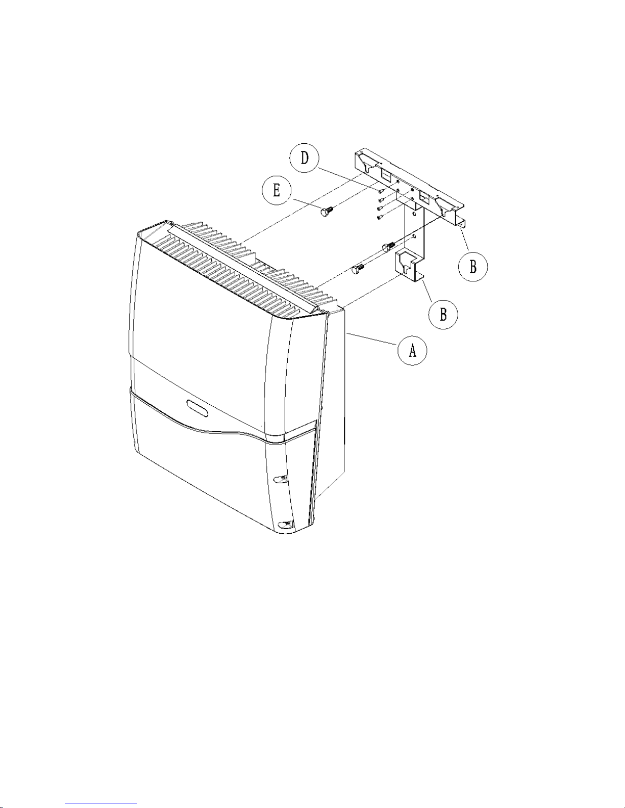
6.1 Assembly Chart
13
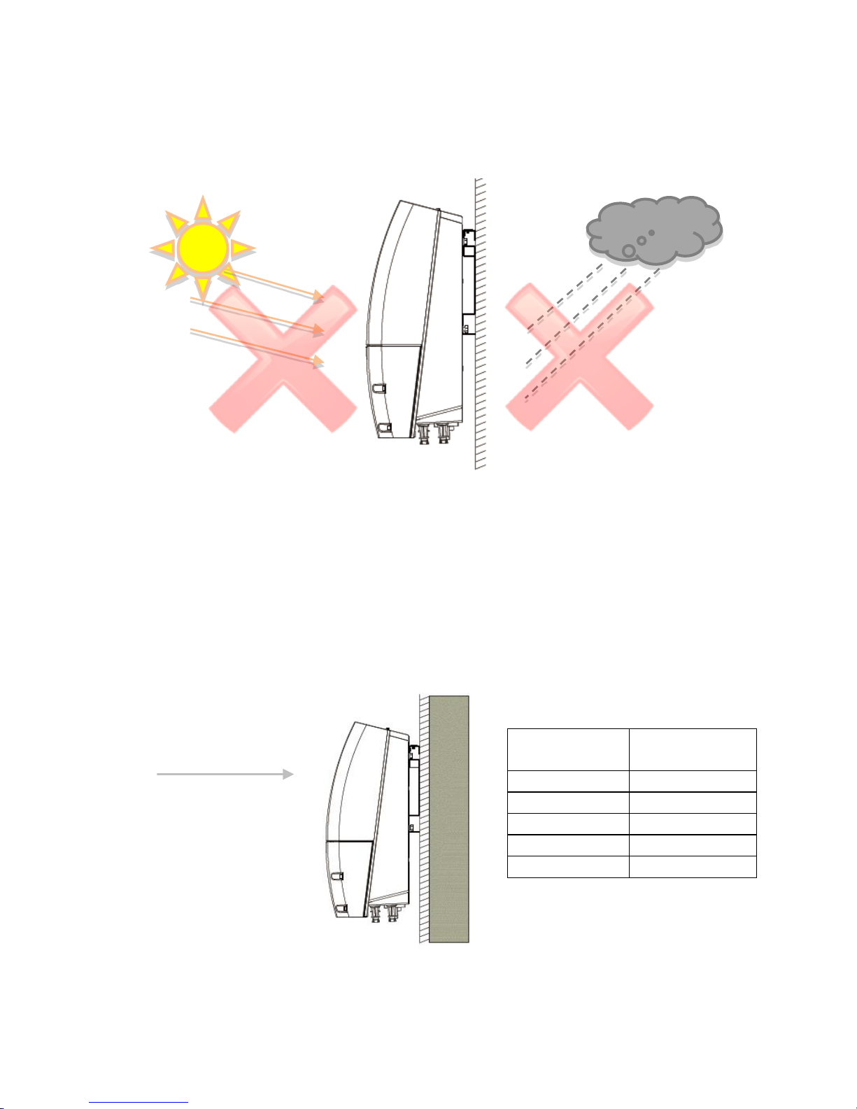
6.2 Choosing Proper Installation Site
Avoid exposing the inverter in direct sunlight or to rain.
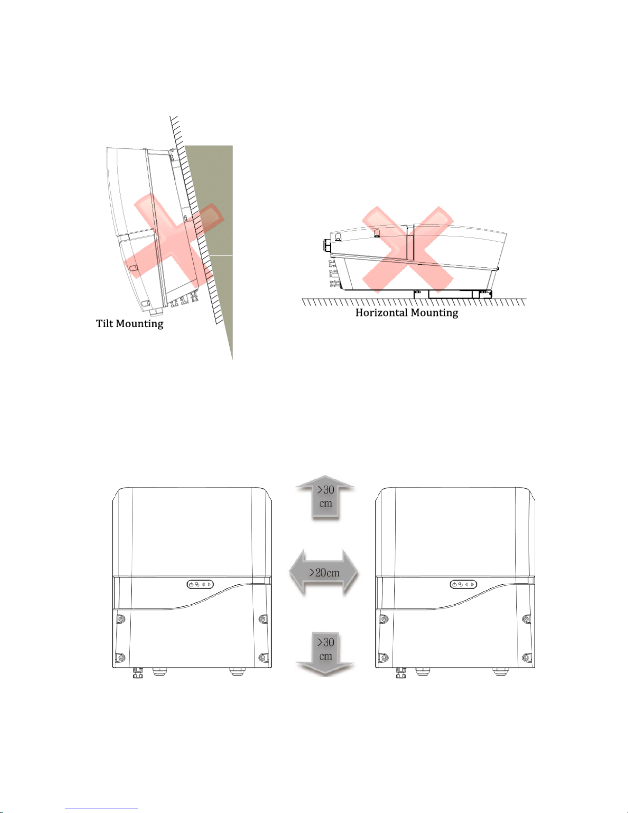
Mount the inverter in vertical direction; tilt or horizontal mounting should be
avoided.
Mounting
Surface
OK or NO
Concrete
OK
Metal
OK
Stone
OK
Plastics/Acrylic
No
Wood
No
Direct Sunlight
Direct Rain
Visible Level
14
6.3 Mounting Properly
Orientation
Keeping Clearance
To retain the good cooling condition, keep each of unit over 20cm left and right,
30cm upper and down and ensure no any object is put around the units to
affect the cooling.

15
6.4 Mounting Procedure
Dimensions of Bracket
The bracket is used to support inverter on wall. Refer to the recommendations
below to complete mounting.
Assembling Bracket
Before fixing on wall, assemble the bracket as below. (use M4 flat Screws x 4) item
Ⓓ of accessory kit.
PV-3000N-V
PV-5000W-V & PV-5000W-HV
16
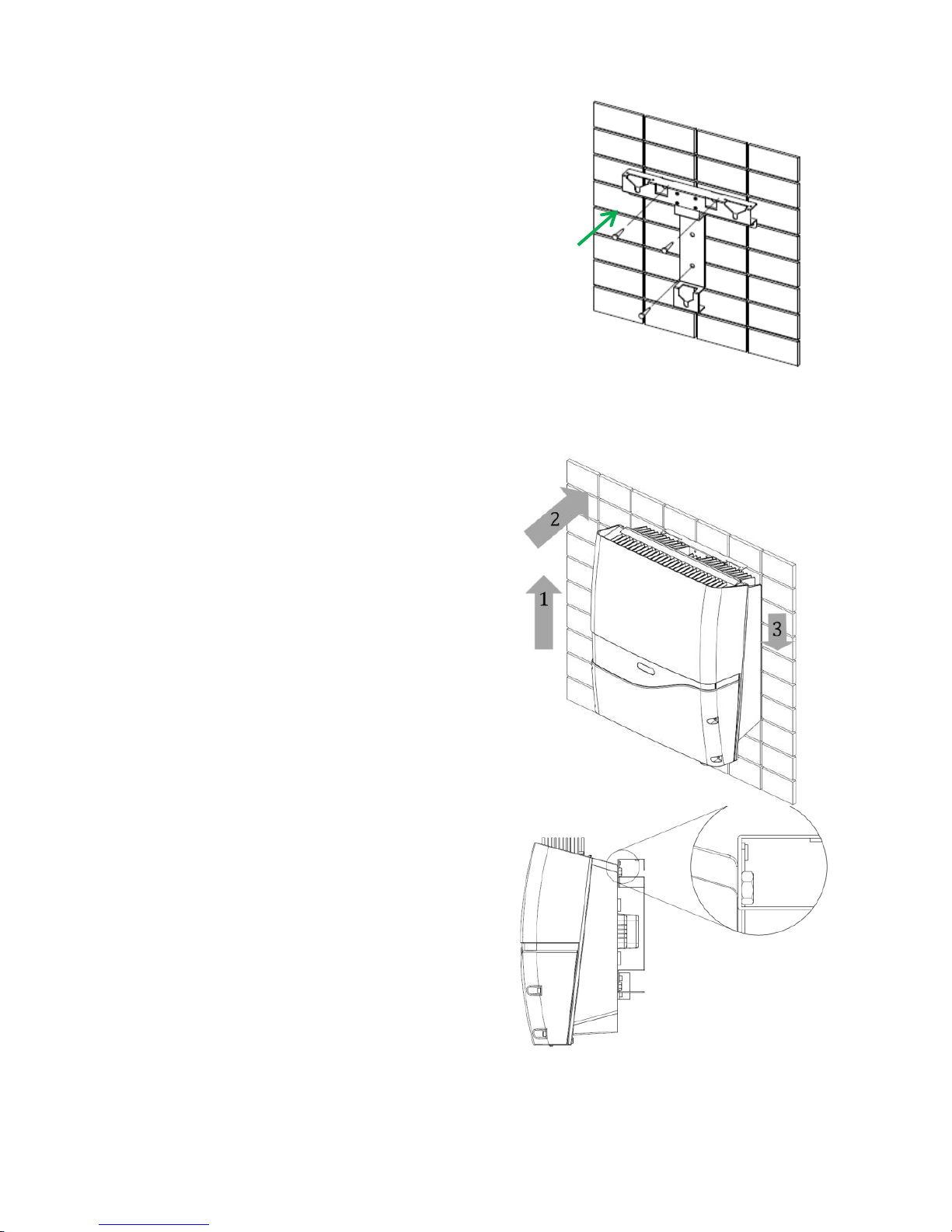
Mounting Bracket
1. Place the assembled bracket on
where the inverter will be installed.
Make proper drill holes and mount
the assembled bracket with screws
from accessory kit. (use item Ⓔ to
install mounting bracket on wall).
2. For safe and firm mounting, make at
least 3 drill holes in a triangular
manner as demonstrated on right.
3. Use Ⓔ item (torque: 1.0-1.2Nm) to
install mounting bracket on wall.
Attaching Inverter
1. Lift inverter slightly higher than
bracket; Make sure all fixing points
on back are at correct positions.
2. Attach inverter on bracket.
3. Hang inverter on bracket slowly.
Checking
1. All supporting points are firm.
2. Lock caps are tightened with
screws.
3. Inverter is well installed and
secured on wall.
③
17
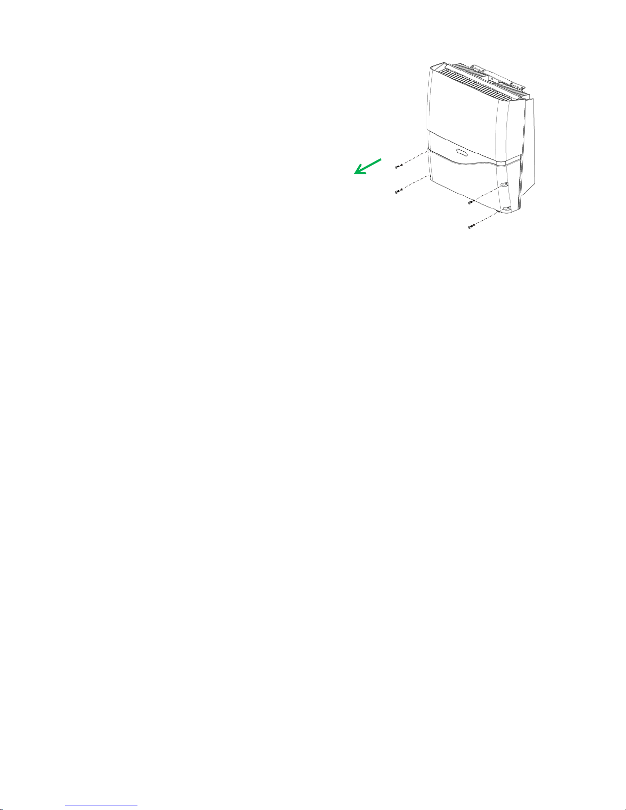
6.5 Wire Connections
Opening Front Cover
1. Remove the 4 screws on cover as shown on
right.
2. Take off the cover gently.
①
 Loading...