

PrimeVOLT PV-5000W-V Installation & Operation Manual
SINGLE PHASE GRID-TIE PV INVERTERS
PV-5000W-V
Installation & Operation Ma nual
〇Safety Precautions
Qualified Personnel ONLY!
Only Qualified technicians shall install o r service unit(s) in
accordance with local wiring regulatio ns.
PV Modules ONLY!
Designed for PV and solar power conve rsion only; do not use
for other DC sources or conversion pur poses.
Hot Surface
Metallic parts of enclosure may be ho t during operation.
Recycle
Do not throw this electronic device in a trash dumpster
when being disposed of. To mi nimize pollution of
environment, please consult your local service provider.
Danger!
High voltage inside inverter can cause e lectric
shock, even when inverter is not operati ng. Wait
for at least 41 minutes before openin g the
enclosure.
41 minutes
1/2
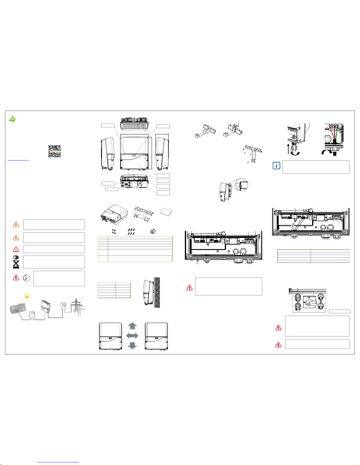
〇Outline & Dimensions
Before beginning your journey, please rea d the following safety instructions
carefully.
〇Installation
■ Unpacking
Recommended Max. DC Power (W)
Max. DC (V)
Max. Current (A)
String
5500
580
9A/String, 18A in Total
2
■Wire Connections
■ AC(Grid) Wiring
Caution!
For safety purposes, place an indepe ndent circuit breaker
between inverter and grid BEFORE all connections. Make sure
inverter will be safely disconnected from the grid in all
circumstances.
It is recommended to use certified 250V /30A circuit breakers.
Note on Cable Selection
It is recommended to use solid cables to ensure steadfastness of
cables on terminal block. If stranded wir es are used, apply coreend materials enclosed in accessory kit fo r all sakes.
■ RS485 & RJ45 Connections
■ DC (PV) Wiring
Be Sure to SWITCH OFF PV
Direct pull-off of DC plugs can lead to sparks. Be sure to switch
off PV before hand.
2. Use either connector
a. Wieland PST40i1C (Preferred)
b. Multi-Contact MC4
3. Connect to PV, After all the associated cables and connectors have been
prepared
4. Remove sealing plugs as depicted on r ight
5. Plug in PV cables gently as depicted belo w
1. DC Input Ratings
614-37089-02
■ Choosing Proper Installation Site
Remind!
1. Using the 600Vdc/20A x 2(tracke rs) circuit breaker between
PV Module with PV Inverter.
2. Only non-grounding PV module is applicable, user is
suggested to consult with system instal ler for PV module
type selection.
3. Require PV modules that have IEC 61 730 class A rating.
SpecificationItem
>30
cm
>30
cm
>20cm
1. Remove sealing plug and twist off th e cable gland (M25)
2. Insert wires from rear of guidance and holes of rubber sealing (M25)
3. Connect RJ45 and RS485 wires as show n below
4. Make sure that RJ45 cable is wound two turns the gray EMI core
5. Tighten cable gland to secure cables firm ly in position
■ Keeping Clearance
Avoid exposing the inverter in direct su nlight or to rain.
Mount the inverter in vertical direction ; tilt or horizontal mounting should be
avoided.
Mounting Surface
Concrete
OK/NO
OK
Metal
Stone
OK
OK
PLastics / Acrylic NO
Wood NO
To retain the good cooling condition , keep each of unit over 20cm left and right,
30cm upper and down and ensure no any object is put around the units to affect
the cooling.
■ Assembling Bracket
Before fixing on wall, assemble the bracket as below.(Use M4 flat screws × 4 item
Ⓓ of accessory kit)
■ Mounting Bracket
■ Checking
1. Place the assembled bracket on where the inverter
will be installed. Make prope r drill holes and mount
the assembled bracket with screws from accessory kit.
2. For safe and firm mounting, make a t least 3 drill holes
in a triangular manner as demonstr ated on right.
3. Use Ⓔ item to install mounting bra cket on wall.
1. All supporting points are firm
2. Lock caps are tightened with screws
3. Inverter is well installed and secured on wall
Warranty Information
Warranty or liability will be void if dama ge caused by, but not limited to the
following:
1. Unauthorized opening of unit
2. Installation faults such as improp er environment, wiring and applications
3. Working conditions beyond spe cified
4. Improper operation of unit
5. Violation of safety instructions in this manual
6. Damage during transportation
7. Any internal modifications
8. Replacing or installation of unautho rized software
9. Unforeseen calamity or force majeu re
Contact Information
〇PV System
DC Switchboard
PV Generator
AC Switchboard
Public Grid
PV Inverter
A typical PV system contains:
1. PV Generator : Receive sunli ght and generate DC power.
2. DC Switchboard : Links between PV panels and PV inverter, include of DC switch
and surge protection.
3. Inverter's DC Switch : PV Inverte r with DC Switch(Optional).
4. PV Inverter : Converts DC power by P V panels to AC output power for public grid.
5. AC Switchboard : Links betwe en PV inverter and public grid.
6. Public Grid : Provides utility for h omes.
1. AC cord configured with M25 ca ble gland, containing waterproof rubber plug
three holes for cable diameter of 4.8 ~ 6.2mm, diameter is recommended to
3.5/5.5/8mm2 of wire. The following factors should be taken into account when
it comes to actual wiring: Ambient te mperature, Wiring nearby, Cooling
2. Recommend to use right M25 cab le gland for Line(L), neutral(N)/ground(PE)
wires
3. Twist off the cable gland and remov e rubber waterproof plug. Remove the
required number of sealing plu g for AC wires
4. Use the cable with appropriated wi re diameter through the rubber waterproof
plug. Then insert the rubber wate rproof plug into the cable gland
5. Remove an appropriated length of the jacket and insulation layer from
cable and crimp the wires wit h terminal
6. Use a screwdriver to fix L(Line), N( Neutral) and ground(PE) wires on the AC
terminal block from left to right si de
7. Tighten cable gland firmly to fix wir es and achieve waterproof effect
Note:Be sure to use the water-proof plugs that you put in order to achieve the waterproof function.
ES-Series
◎
ES-Series
◎
Your PV Inverter Professional
PrimeVOLT
Asian Power Devices Inc.
(Trade mark: PrimeVOLT )
www.primevolt.com
1. AC Cable Gland M25 (AC cabl e)
2. Signal Cable Gland M25 (Ethernet/RS48 5)
3. AC terminal block
4. RS485 terminal
5. RS485 terminal resistor switch
6. RS485 address selector
7. RJ45 port for Internet access
8. Ripple Control Receiver (RCR) termi nal
9. USB connector
190mm418mm
485mm
Status LED
Front Cover
AC Cable
Guidance
Signal Cable
Guidance
Button & LED
Display LCD
DC (PV) Input
DC Switch
Ⓐ Ⓑ Ⓒ
Ⓓ Ⓔ
Ⓕ
*
Black EMI core x 1(Ethernet cable RJ45)
DescriptionItem
Ⓐ Inverter
Ⓑ
Ⓒ
Ⓓ
Ⓔ
Ⓕ
Mounting bracket kit
User manual
M4(8mm) flat screws × 4, used for mounting bracket
Plastic anchors & screws(Φ6.5*32mm) × 3. Used to install mounting
bracket on wall
RS485 Port
RJ45 Port (Internet)
L
N
②
①
③
⑨
④ ⑤ ⑥
⑦ ⑧
L
N
L
N
⑥
③
④
PV1(+) PV1(-)
PV2(-)PV2(+)
DC Switch
Internal fault detected
Please keep DC breaker of solar panels off
Grid voltage below range
Measured voltage displayed
AC VOLT LOW
VacXXX/XXX/XXX V
AC FREQ HIGH
fac XXX.X Hz
Grid frequency over range
Measured frequency displayed
AC FREQ LOW
fac XXX.X Hz
Grid frequency below range
Measured frequency displayed
PV VOLT HIGH
Vdc XXX/XXXV
Solar panel voltage over range
Measured voltage displayed
PV ISUL LOW Check for insulation of solar panels failed
GFC HIGH
Ig XXX mA
Leakage current high
Measured current displayed
C1
C2
High DC current detected
Relay failed
C3
C4
DC current sensor failed
Internal temperature high
C5
C7
GFCI detection failed
Anti-islanding detection failed
FAN FAILS
F1
Fan not working properly
Bus voltage low
F2
F3
Bus voltage high
CPU communication abnormal
F4
F5
Mismatch of firmware version between CPUs
EEPROM memory faulty
F6
F7
Error on system consistency
Over-current in inverter detected
F8 Slow start-up on Bus
Grid voltage over range
Measured voltage displayed
AC VOLT HIGH
VacXXX/XXX/XXX V
ES-Serial Description
■ Error Message
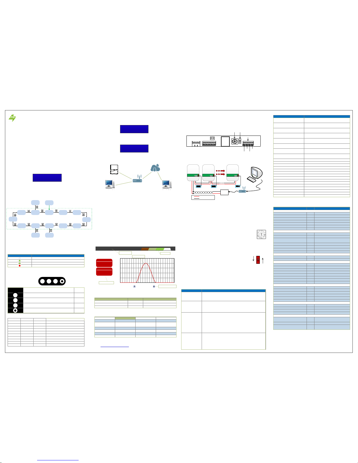
Input (DC)
Recommended Maximum Power W 5500
MPPT Working Range V 180 ~ 580
MPPT Range(full load) V 290 ~ 500
Maximum DC Voltage V 580
Maximum DC Current A 10x2
No. of MPP Trackers 2
Max. backfeed current to array mA 1.6
Output (AC)
Nominal Power W 5000
Maximum Power W 5000
Nominal Voltage V 220/230/240
Nominal Frequency Hz 50/60
Power Factor -0.8 ~ +0.8
Maximum Current A 23.8
Max. O/P Over-Current Protection A 45
Efficiencies
Max. Efficiency % 97.2
Euro- Eta % 96.1
General
Temp. Range °C -25 ~ 55
Temp. (Full Power) °C -20 ~ 45
Topology Transformerless
Protection IP65
Humidity % 0 ~ 100
Cooling Force-Air Cooling
Protection Class I
Overvoltage Cat.
DC input:II、AC input:III
Features(ES-Series)
LCD 1602 character display
RS485 Standard, half-duplex
Network
Cable Network (RJ45)、Wi-Fi(Optional)
Data Logging Yes, 3 years
Web Server Yes
Clock Synchronization Automatically sync with time server
Mechanical
W x H x D mm 418 x 485 x 190
Weight kg 22
Input Pairs 2
DC Switch Built-in
Compliances
Grid Monitoring
VDE-AR-N 4105
VDE0126-1-1/A1、PEA/MEA、G83-2
Safety
IEC 62109-1、62109-2
EMC
EN 61000-6-2、EN 61000-6-4
EN 61000-3-11、EN 61000-3-12
Note: Specifications are subject to change without prior notice.
〇Specifications
■ Wiring Diagram
Inverter Info. PV-5000W-HV Date & Time Jan/1/2016 2:04:33
Voltage Range 184.0 ~ 264.5 V Frequency Range 50 Hz
Grid Regulation VDE-AR-N 4105
IP Address 192.168.60.43 Wi-Fi (Edit)
Auto FW Update ON Language English
Feed-in Rate $0.32 Administration admin
UPLOAD (Edit)
When in Settings sheet, you will see the table below.
■ Settings
〇Browsing Inverter Web Page(ES-Series)
■ Basics
Inverter has a built-in and multi-functio nal web page that user can access via LAN/
WLAN. The recommended web browsers ar e Internet Explorer, Firefox and Safari.
Follow the steps below to explore the i nverter web page.
1. Make sure you have successfully conne cted inverter to a LAN by either Ethernet
or Wi-Fi.
2. Tap button to switch to “Operation Fram e” to read off the inverter’s IP address.
3. Open a web browser on your desktop/ laptop, key in the IP address you have
read previously at the address bar
4. Daily graphs will load soon after.
〇Network and Internet(ES-Series)
■ Accessing Inverter via LAN (Local Area Network)
The illustration above demonstrates ho w to access the inverter via Internet. Similar
to LAN, the inverter can be accessed by we b browser. However, there is usually a
firewall that would block direct access of the LAN from the Internet. In order to
overcome this, you will need to set up NA T (Network Address Translation) or Port
Forwarding of the router. For detailed information, please refer to the manual
provided by your router supplier.
Information Board
Inverter Status
Daily Graphs
Forward/Backward Tabs
Display Tabs
■ Error Message Display
KEEP PV OFF
614-37089-02
Function Unit Specification
〇RS485 Communication Interface
■RS485 hardware interface
Address
Switch
Terminal
Resistor Switch
RS485 terminal
T/R 1+ T/R 2+
T/R 1- T/R 2-
ES-Series
◎
■ Address Setup(ES-Series)
To do this setting, use the address rot ary switch shown on right. For a
single inverter, set the position to “1”; for multiple inverters, please assign
them different positions with no dupl ications. Since only 15 positions (1~F)
are available, the maximum number of inverters that can be grouped at a
time in a RS485 bus is 15.
■ Setting the Terminal Resistor
As shown on right, “ON” indicates a resisto r is added. ONLY the
terminal-end inverter (last inverte r of the row) should have this switch
set to “ON”. Switches of the other inve rters should be set as “OFF.”
ON
OFF
5.0kW
4.0kW
3.0kW
2.0kW
1.0kW
0.0kW
0 1 2 3 4 5 6 7 8 9 10 11 12 13 14 15 16 17 18 19 20 21 22 23 24
2016 / 01 / 01
Production
System
Now
Today
Total
Vac
Vdc
Fac
50000W
22.2kWh
23.8kWh
230V
650.1 V
50.1 Hz
Grid-Connected
PV-5000W-HV
DAYSETTINGS LOGS MONTH
ON
1
■ LCD display
Buttons are used to change frame display on LCD screen.
DescriptionIcon Note
LED A,Reference LED fault table A
LED B,Reference LED fault table B
LED C,Reference LED fault table C
Button
2/2
CBA
A
B
C
Pac 5000W
Etoday 50.5kWh
Computer via LAN
Router/Modem
Computer via Internet
Inverter
■ Logs
Event records of inverter. Events inclu de activities and errors of inverter. See
picture below for demonstration
When inverter encounters an error, LC M screen enter error mode and an error
message will be displayed on LCM screen continuously. The maximum is 5 in ESserial For more detail content, please refer to the“error message”chapter.
2016/01/20 10:26:12 System StartedInformation
2016/02/27 15:25:24 AC FREQ HIGHError
2016/01/22 11:23:15 Frequency range changedInformation
Time EventType
■ Cloud Monitoring
Trouble Suggestions
No display or
incorrect display
No generation
(No Error)
1. Check PV wiring.
2. Check PV polarities.
3. Check PV voltages.
4. Wait for stronger sunlight.
Error on display
1. Check PV module installation.
2. Check the PV module is damage d or sheltered.
3. Ensure inverter is not in direc t sun light.
4. Remove all objects on inverter .
5. Check the setting space of each in verter.
6. Check inverter’s ambient temper ature and coiling condition.
Generated power
less than expected
Refer to error table in Error Frame section .
1. Error other than “C#”: Check the er ror message and take
suitable action.
2. “C#” Error: Switch off the AC br eaker then the DC breaker.
Switch on the DC breaker then th e AC breaker again.
3. If “C#” error persists, call your local service provider for
assistance.
1. Check AC connection segments such as fuses, breakers and
wires. Be sure AC is connected t o inverter properly.
2. Switch AC off and on again.
■ Troubleshooting
In cases where an inverter detects a pro blem, an error message may be conveyed
by the system. Use the table below t o resolve accordingly. If the problem persists,
contact your local service provider for further assistance.
〇Maintenance
Go to http://mypowermanager.net to down load the user manual of cloud and
register your user account to set up you r inverters for cloud monitoring.
1. Connect T/R+ and T/R- of RS485 converter to the T/R1+ and T/R1- of the data logger
respectively.
2. Between two data loggers, match T/R2+ and T/R2- of this inverter to T/R1+ and T/R1 of the next inverter.
3. Set terminal resistor switch “ON” of the terminal-end inverter (last data logg er of the row)
only. The others’ should be set as “OFF.”
4. Connect data logger and router of RJ45 Cable.
T/R -
T/R +
T/R - T/R1 -
T/R + T/R1 +
RJ45 Cable
RJ45 Cable
Data
Logger
Router
Pin:Off Pin:Off Pin:On
Inverter
RS485 Connector
ON
1
Inverter
RS485 Connector
ON
1
Inverter
RS485 Connector
ON
1
〇Operation
ES-Series
◎
■ Status LED
The LED on the inverter right side wil l show the inverter operation status by
different colors. In normal operatio n, the LED appears in green color; in error
circumstance, it appears in red color.
IndicationStatus
Solid Green: Inverter is standing by/operating (day).
Flashing Green: Inverter is standing by (evening/night).
Solid Red: Inverter is having a fault.
Inverter is not connected to AC.
■ LED Fault and LED Indication
Error Message
LED A LED CLED B
Off Off Off All Normal
ON
Off Off High DC Current Detected
Off
ON
Off Relay(s) Failed
ON
Off Off DC Current Sensor(s) Fail ed
ON ON
Off Internal Temperature High
Bus Failed
GFCI Detection Failed
ON
Off
ON
Off
ON ON
Check for insulation of solar panels failed
Leakage Current High
Fan not Working Properly
Blink
Off
Off Off
Blink
Off Off
Blink
Note:Blinking means LEDs on for 0.5 seconds and off for 0.5 seconds.
LED fault table
AC VOLT HIGH
Vac 271/ 262/ 261V
■ Operation Chart
The inverter error that has occurred most recently is generally recorded by the
history error.
■ Error Message Display
History Error
Message Record
Output Power
Daily Energy
LAN IPWi-Fi IP
AC Voltage
AC Current
Safety Mode
Model
F/W Version
Modbus
Adress
5 Seconds
WELCOME
DC Voltage
DC Current
E-Total
H-Total
Date/Time
VAC/FAC
Range
Error Record
Clock
Setting
F/W Version
History Error
Record
Press
Press5 Seconds
Press5 Seconds
5 Seconds
When inverter has connected to electrica l grid and started generating power, the
LCM screen enters regular mode. The LC D display flow chart sequence of on-screen
information is as the frames as below .
Off
Your PV Inverter Professional
PrimeVOLT
Your PV Inverter Profess ional
PrimeVOLT
E S-Se ries offer s basic logger functionalit ies with simple and necessary onscreen information form.
The pro duction using for RS485 or R J 45 t o monitor the inverter working
status, and provide the LED and LCD d isplay, the LCD is 16*2 character type.
The LED panel has three LED lights and one button. When a fault occurs, one
or two or three LED lights will be blink ing in response.
The display content s include outp ut power、grid voltage & current、PV
module voltage & cu rrent、energy of today ( E-Today)、 accumul ated ener gy
(E -To ta l) 、totally op er at ion time (H -T ota l) 、regulation setting ( Saf et y
Mode)、model name and firmware v ersion.
 Loading...