

Page 1

1
OPERATOR’S MANUAL
AND PARTS LIST
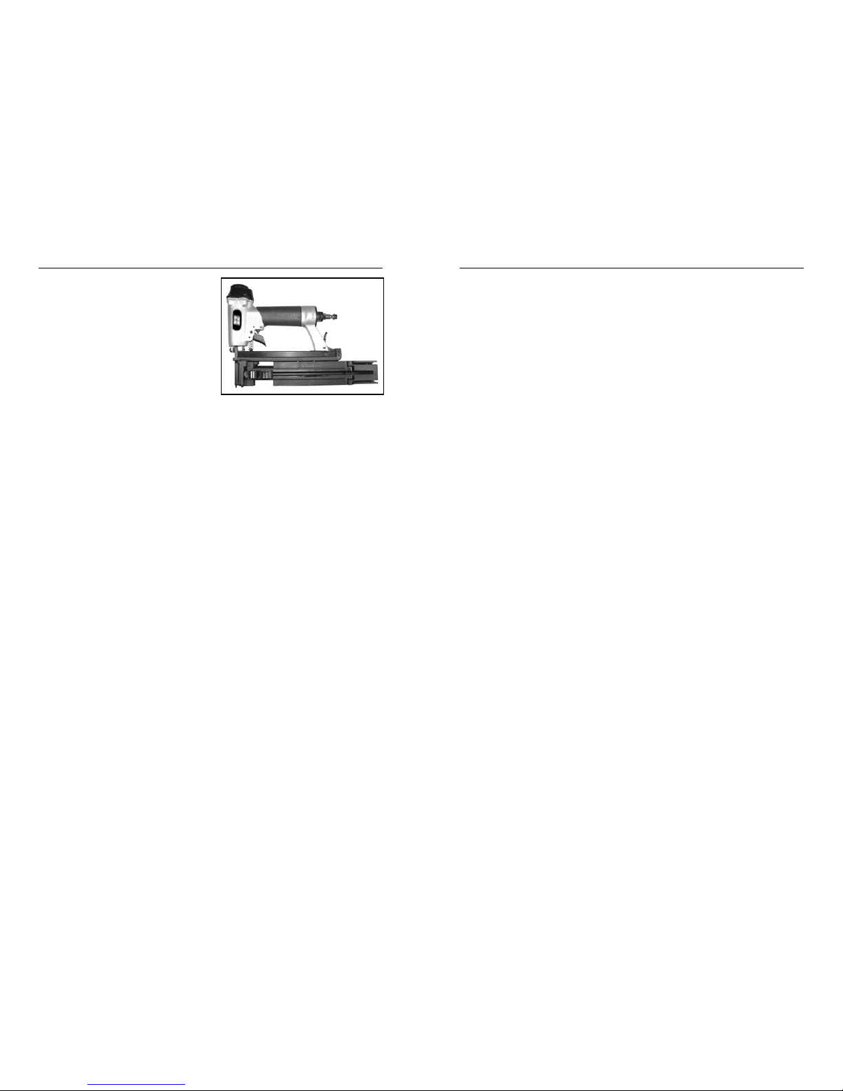
MODEL GRC58A
PLASTIC CAP STAPLER
Distributed By
www.grip-rite.com
Page 2

32
TABLE OF CONTENTS
TABLE OF CONTENTS -------------------------------- 2
SPECIFICATIONS --------------------------------------- 3
SAFETY ---------------------------------------------------- 4
TOOL PARTS --------------------------------------------- 8
PARTS DESCRIPTION--------------------------------- 9
LOADING FASTENERS ----------------------------- 10
LOADING PLASTIC CAPS --------------------------- 11
OPERATION--------------------------------------------- 12
MAINTENANCE ---------------------------------------- 13
PARTS SCHEMATIC---------------------------------- 14
PARTS LIST --------------------------------------------- 15
TROUBLESHOOTING ------------------------------- 16
WARRANTY --------------------------------------------- 18
SPECIFICATIONS
SPECIFICATIONS
MODEL GRC58A Plastic Cap Stapler
STAPLE GAUGE 21 GA. (.080”) (2 mm) Flat Wire Staples
STAPLE SIZE 1/2” (12.8 mm) Crown x 5/8” (15.8 mm) Long
STAPLE CAPACITY 110 Staples
PLASTIC CAP DIA. 1-1/32” (26.2 mm) Diameter Plastic Caps
CAP CAPACITY Cordel - 110 Caps (1 Strip)
Laser - 110 Caps (2 Strips)
PLASTIC CAP FEED Automatic/Pneumatic Cylinder
MAX AIR PRESSURE 120 (8.3 bar) psi
MIN AIR PRESSURE 100 (6.9 bar) psi
TOOL WEIGHT 4 lbs. (1.8 kg)
TOOL LENGTH 12 1/4” (31.1 cm) Magazine Closed
18 1/8” (46 cm) Magazine Open
TOOL HEIGHT 8.5” (21.6 cm)
TRIGGER TYPE STD. DUAL ACTION
AIR INLET 1/4 NPT
AIR CONNECTION QUICK CONNECT
LUBRICATION 10W Air Tool Oil (Provided)
IMPORTANT SAFETY INFORMATION
You must read this entire manual and familiarize yourself with all
safety, operating, and service instructions before loading, handling,
or using your tool. When used correctly, pneumatic fastening
tools provide a lightweight, powerful, and safe means of fastening.
Used improperly, these tools can cause serious injury to you and
those around you.
IMPORTANT FASTENER INFORMATION
Only GripRite™ GRCP5822 & GRCP5822L 5/8” Cap Pack Staples
and adhesive/string or laser weld plastic caps fit this tool. Use of
any other type of staple or cap will cause tool to malfunction.
Page 3
54
SAFETY
SAFETY
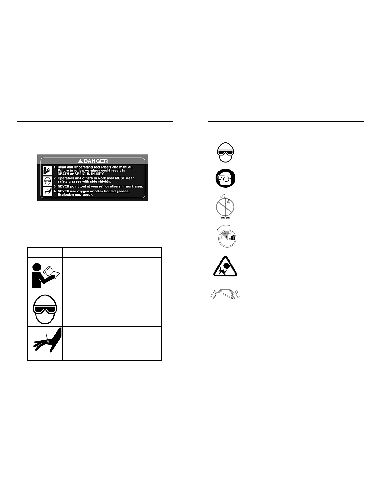
SAFETY LABELS
This pneumatic fastening tool includes a warning label to help remind you of
important safety information when operating the tool. The safety label must be
legible at all times, and must be replaced if it becomes worn or damaged.
SAFETY SYMBOLS
The safety symbols on the safety label provide a visual reminder of
basic safety rules, and the personal injury hazard that may arise if
all safety and operating instructions are not followed. Make sure
you understand the meaning of each of these symbols, and protect
yourself and others by obeying all safety and operating instructions.
SYMBOL
DESCRIPTION
READ THE MANUAL - The manual contains
important safety and operating instructions
that must be followed. All tool users must
read the manual before using the tool.
WEAR SAFETY GLASSES - Tool operator
and bystanders must wear safety glasses
with side shield that meet ANSI Z87.1
requirements.
RISK OF PERSONAL INJURY - Failure to
follow all safety and operating instructions,
or misuse of the tool, can result in serious
injury to tool operator and bystanders.
WEAR SAFETY GLASSES
Always wear safety glasses with side shields that meet ANSI
Z87.1 requirements when operating the tool. Make sure all
others in work area wear safety glasses.
WEAR HEARING PROTECTION
Wear hearing protection to protect your hearing from noise.
Prolonged exposure to loud noise can result in hearing loss.
NEVER OPERATE THE TOOL WITH OXYGEN OR OTHER
BOTTLED GASES
Oxygen and other reactive or high-pressure bottled gases
can cause the tool to explode. Use clean, dry regulated
compressed air from a properly operating air compressor.
DO NOT EXCEED MAXIMUM RECOMMENDED OPERATING AIR
PRESSURE OF 120 PSI /8.3 Bar.
Exceeding the maximum recommended air pressure can
cause the tool housing to burst, or cause premature failure of
components.
NEVER CONNECT THE TOOL TO AN AIR SUPPLY THAT HAS
THE POTENTIAL TO EXCEED 180 PSI/12.4 Bar.
Using a regulated air supply with a line or tank pressure
greater than 180 psi can cause the tool to burst if the air line
regulator fails suddenly.
USE AN AIR HOSE RATED FOR 180 PSI/12.4 Bar OR
GREATER
Always use air hose rated to handle 180 psi or the maximum
potential pressure of the air supply.
ONLY USE A RELIEVING-TYPE AIR COUPLING IN THE TOOL
AIR INLET OPENING.
Use of a non-relieving air coupling on the tool can trap air
inside the tool housing, and allow the tool to drive a fastener
even after the air hose has been disconnected.
SAFETY INSTRUCTIONS
120 psi
6.9 bar
100 psi
8.3 bar
Page 4

76
SAFETY
SAFETY
DO NOT ATTEMPT TO OPERATE THE TOOL IF THE TOOL’S
OPERATING CONTROLS HAVE BEEN MODIFIED OR ARE NOT
WORKING PROPERLY.
Attempting to use a tool with modified or malfunctioning
trigger or workpiece contact can result in a fastener being
driven unintentionally.
USE CORRECT FASTENERS AND PLASTIC CAPS FOR TOOL
Only use the correct cap and fastener for the tool. Using
caps or fasteners with incorrect specifications can jam the
tool or cause serious injuries.
USE THE CORRECT FASTENERS FOR THE APPLICATION.
Using the wrong fasteners can cause the workpiece to split
and allow the fastener to fly free.
KEEP TOOL POINTED IN A SAFE DIRECTION WHEN LOADING
FASTENERS.
Never point the tool at yourself or anyone else when loading
fasteners.
DO NOT LOAD TOOL WITH TRIGGER OR WORKPIECE
CONTACT DEPRESSED.
Depressing the trigger or workpiece contact during loading
can result in an unintentional fastener drive if both devices
are accidentally actuated at the same time.
KEEP FINGER OFF TRIGGER UNTIL TOOL IS IN POSITION TO
DRIVE A FASTENER.
An unexpected bump or sudden contact with your body or that
of a bystander can result in serious injuries.
AVOID DRIVING FASTENERS INTO KNOTS, ON TOP OF
OTHER FASTENERS, AT WORKPIECE EDGES, OR INTO
BRITTLE MATERIALS.
Driving fasteners into extremely hard materials, or driving into
workpiece edges, can cause fasteners to deflect away from
the workpiece. Flying fasteners can cause serious injuries.
SAFETY INSTRUCTIONS
KEEP HANDS AND BODY PARTS AWAY FROM AREA BEING
FASTENED.
Fasteners can deflect and turn as they are being driven into
the workpiece, and penetrate fingers, hands, and other body
parts that may be in the fastening area.
DO NOT OVERREACH OR WORK WHILE ON UNSTABLE
FOOTING
If you lose your balance while fastening, you could drive a
fastener into yourself or a bystander.
DO NOT USE TOOL IF TOOL MALFUNCTIONS OR BEGINS
LEAKING AIR.
Operating a malfunctioning tool can result in an unexpected
fastener discharge and injury to yourself or others.
DISCONNECT THE TOOL FROM THE AIR SUPPLY TO RELOAD, CLEAR JAMS, OR PERFORM MAINTENANCE.
Never attempt to reload a tool, clear a jam, or perform
maintenance without first disconnecting the air supply.
NEVER LEAVE A LOADED, PRESSURIZED TOOL
UNATTENDED
A loaded, pressurized tool could be picked up or handled by
someone who is unfamiliar with the tool or that has not read
the tool manual.
KEEP TOOLS OUT OF THE REACH OF CHILDREN
Place the tool back in the tool box after use, and store the tool
out of reach.
DO NOT MODIFY TOOL
Modifications can cause a tool to be unsafe and can cause
the tool to operate improperly.
SAFETY INSTRUCTIONS
Page 5
98
DESCRIPTION
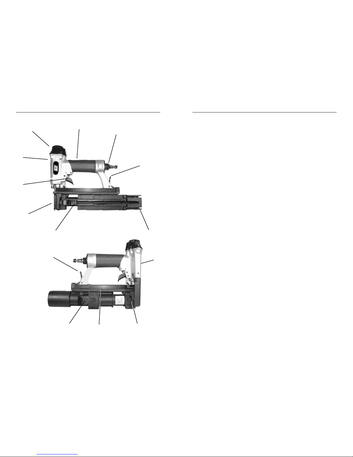
PART DESCRIPTIONS
1. Cylinder Cap - Covers main valve and piston assembly.
2. Handle - Cushioned handgrip provides comfortable operation.
3. Air Coupling - Quick-disconnect male coupling allows quick
connection to air hose. Dust cap keeps dirt out when tool is not in
use.
4. Magazine Release - Opens fastener magazine for quick reloading
fasteners.
5. Cap Tower Door - Pivots open to permit fast reloading of plastic
caps into high capacity cap tower.
6. Follower Handle - Pull back to release tension on plastic caps and
open cap tower door.
7. Workpiece Contact - Spring-loaded contact mechanism prevents
tool from driving a fastener unless tool is pressed down and held
against a work surface.
8. Dual Action Trigger - Actuates tool when workpiece contact is
depressed against work surface. Permits contact-trip (bump fire) or
trigger-fire operation.
9. Tool Housing - Contains tool components and provides air storage
for consistent fastener drive.
10. Cap Cylinder - Air-powered cylinder drives cap feed hook. Automati-
cally feeds plastic caps for rapid cap application.
11. Cap Feed Hook - Feeds caps into fastening position.
12. Fastener Magazine - Hold fasteners securely and provides positive
feeding of fasteners into driving position.
13. Belt Hook - Durable tool hook slides on belt. Holds tool securely
and keeps it in reach for greater productivity.
Metric Hex Wrenches - Included with tool to allow tightening of
metric screws. Keep tools in tool case for periodic tightening of
screws.
Air Tool Oil - Lightweight oil formulated for use in air tools provides
proper lubrication to o-rings and internal parts.
Safety Goggles - Provide required eye protection
DESCRIPTION
TOOL PARTS
1
2
4
3
12
5
8
6
11
10
9
7
4
13
Page 6
1110
OPERATION
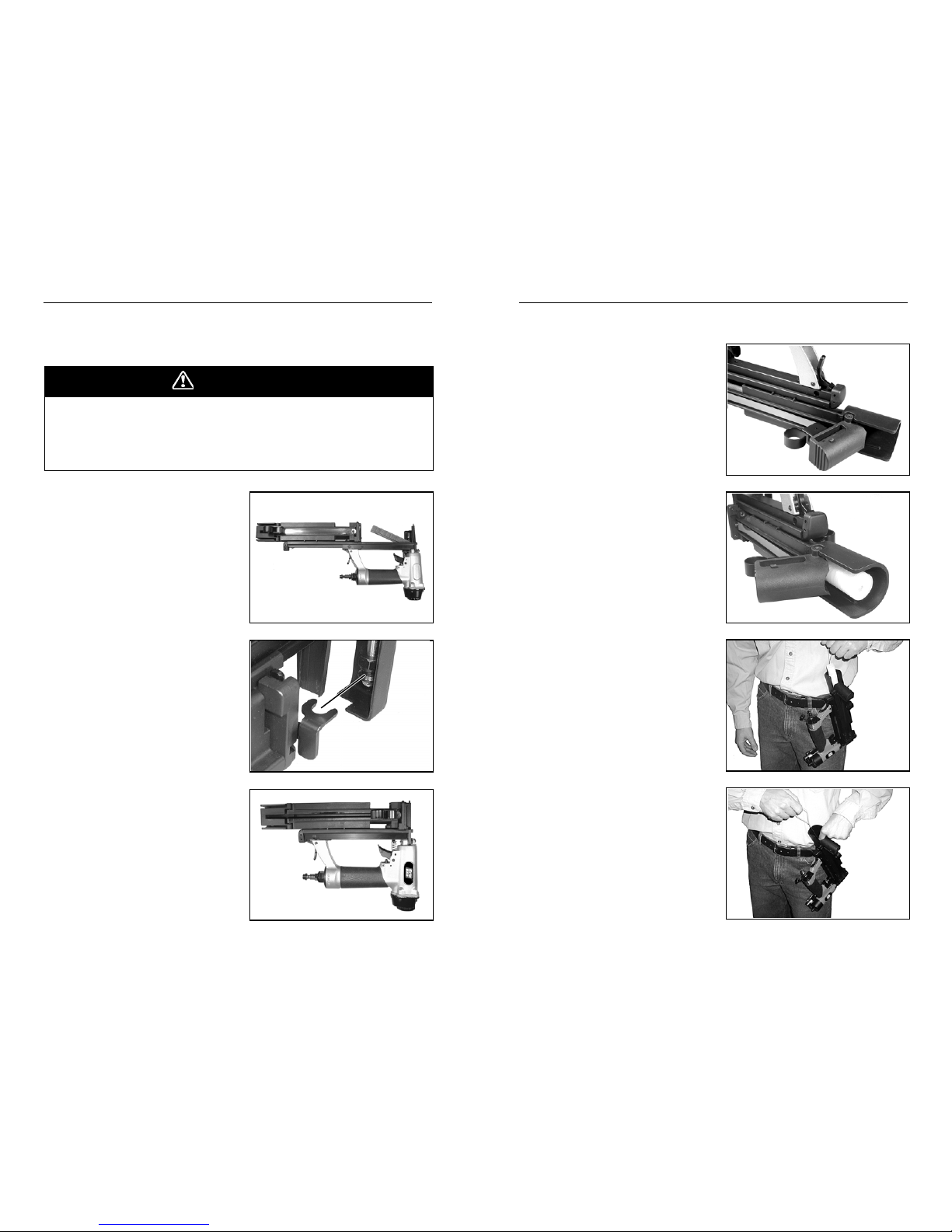
LOADING PLASTIC CAPS
LOADING INSTRUCTIONS
1. Disconnect tool from air supply
using quick-connect coupling.
2. Open loading tower door by
pulling follower handle all the
way back, then out and away
from magazine.
3. Laser weld caps:
Load two complete strips of
GripRite™ plastic caps into
tower. “UP” side of caps face
out. Top of cap stack must fit
below rim inside tower.
Skip to step 5.
4a. String/adhesive caps:
Hang tool on belt using belt
hook. Load one complete strip
of GripRite™ plastic caps into
tower. Top of cap stack must
fit below rim inside tower.
4b. Hold cap stack down, and pull
plastic string completely free of
stack using other hand. Discard string. Lift tool off belt.
OPERATION
LOADING FASTENERS
LOADING INSTRUCTIONS
1. Disconnect tool from air supply
using quick-connect coupling.
2. Depress magazine latch, and
slide magazine cover open.
3. Place one strip of GripRite™
GRCP5822 staples into
magazine.
4. Before closing magazine,
check cap driver hook position
for correct alignment with
recess on cap cylinder bolt,
and reposition hook if necessary. See alignment label on
side of cap tower.
5. Slide magazine cover closed.
Magazine must click into
latched position.
6. Load plastic caps as shown on
next page.
A fastener can be driven unintentionally if the trigger and safety bracket
are activated at the same time. Always disconnect tool from air supply
before loading fasteners or plastic caps, or performing any service on
tool. Keep finger off trigger until ready to drive a fastener.
DANGER
Page 7
1312
MAINTENANCE
CONTACT TRIP (BUMP FIRE) DRIVING METHOD
1. Position the nose of the tool over the work surface, near the area
where the first fastener/cap is to be driven.
2. Squeeze and hold the trigger in the depressed position.
3. Bump the workpiece contact (safety) against the work surface at
each point where a fastener/cap is to be driven.
4. Using a bouncing motion, continue moving the tool into position for
each fastener drive/cap attachment.
5. When fastening is completed, release the trigger.
MAINTENANCE
Your tool will last longer and perform better if periodic maintenance is
performed. Please use the information below to keep your tool operating in
top condition.
Lubrication
Disconnect tool from the air supply and remove all fasteners. Apply three
drops of air tool oil (provided) in the air inlet before each use, and after
every 1000 fasteners driven. If the tool will be used outside in the winter,
use a winter grade air tool oil to help keep frost from forming inside the
tool. Do not use other types of lubricants on this tool, as other lubricants
may contain chemicals harmful to o-rings and other tool components.
Cleaning
Disconnect tool from the air supply and remove all fasteners. Brush tool
off using a parts cleaning brush or clean rag. Open magazine and brush
out dirt and debris. Check area around trigger and workpiece contact,
and clean as necessary.
Workpiece Contact & Trigger
Check workpiece contact for proper operation before each use. Workpiece
contact must move freely and return to extended position when lifted from
workpiece. Trigger must operate freely.
Daily Inspection
• Check for broken, damaged, or excessively worn parts, and repair
or replace as needed.
• Check for air leaks at trigger, cap, and nose. Disconnect tool from
air supply immediately if leaks are present, and see dealer for
service.
• Make sure all screws are tightened securely.
OPERATION
TRIGGER FIRE METHOD
1. Hold the tool securely using the handgrip. Keep finger off trigger
until tool is in position and you are ready to drive a fastener.
2. Position the nose of the tool on the workpiece, placing the nose at
the desired fastener driving position.
3. Press the tool down firmly against the work surface, fully depressing
the workpiece contact (SAFETY).
4. Squeeze the trigger once and release to drive a fastener. (NOTE:
First fastener driven after reloading plastic caps does not include a
cap. Cap feeds into fastening position after first fastener is driven.)
5. Lift the tool off the work surface to reset the workpiece contact.
6. Check fastener for flush drive against plastic cap, and adjust air
pressure setting on compressor to obtain desired fastener drive.
7. Increase air pressure to drive deeper or to drive into harder materials.
Reduce air pressure to reduce drive or to drive into softer materials.
For longest tool and part life, always use the lowest air pressure
necessary to drive fasteners to desired depth.
8. Position the tool for driving the next fastener, and repeat the above
procedure. Always keep hands and other body parts away from
areas being fastened.
OPERATION
LOADING INSTRUCTIONS (Cont’d)
5. Pull follower handle back and
in to close tower door. Door
must click into locked position.
6. Slide follower handle forward,
and release.
7. Connect tool to air supply
using quick connect coupling.
8. Drive one fastener to advance
plastic cap into fastening
position.
9. Tool is now ready for fastening
caps as desired.
Page 8

1514
PARTS LISTPARTS SCHEMATIC
ITEM P/N DESCRIPTION
1 GRBN312 DEFLECTOR
2 GRBN308 BOLT ASSY
3 GRBN313 CA P
4 GRBN296 SEAL
5 GRBN314 COMPRESSION SPRING
6 GRBN297 O - RING
7 GRBN306 O - RING
8 GRBN315 HD.VALVE PISTON
9 GRBN316 O - RING
10 GRBN317 CYLINDER CAP SEAL
11 GRBN318 COLLAR
12 GRBN161 O - RING
13 GRBN319 DRIVER UNIT
14 GRBN320 O - RING
15 GRBN321 CYLINDER
16 GRBN160 CYLINDER RING
17 GRBN295 BUMPER
18 GRBN164 DRIVER BLADE GUIDE
19 GRBN322 O - RING
20 GRBN323 TRIGGER VALVE HEAD
21 GRBN174 SPRING
22 GRBN324 PLUNGER
23 GRBN307 O - RING
24 GRBN325 O - RING
25 GRBN326 O - RING
26 GRBN327 PLUNGER CAP
27 GRBN181 TRIGGER PIVOT PIN
28 GRBN305 HEX.SOC.HD.SCREW
29 GRBN328 ROLL PIN
30 GRBN329 ROLL PIN
31 GRBN231 ROLL PIN
32 GRBN182 URETHANE RETAINER
33 GRBN298 SAFETY
34 GRBN299 TRIGGER
35 GRBN186 ROLL PIN
36 GRBN180 SAFETY GUIDE
37 GRBN330 SAFETY SPRING
38 GRBN293 GUN BODY UNIT
39 GRBN300 O - RING
40 GRBN301 END CAP
41 GRBN331 AIR PLUG CAP
42 GRBN28 AIR PLUG
43 GRBN309 BOLT ASSY
44 GRBN194 HEX.SOC.HD.BOLT
45 GRBN195 DRIVER GUIDE COVER
46 GRBN310 GASKET
47 GRBN197 MAGAZINE B
48 GRBN332 SAFETY
49 GRBN199 BRACKET
50 GRBN285 HEX.SOC.HD.BOLT
51 GRBN201 FLAT WASHER
52 GRBN202 HEX.SOC.HD.BOLT
53 GRBN203 PUSHER
ITEM P/N DESCRIPTION
54 GRBN204 MAGAZINE A
55 GRBN205 PROT. HOOD COVER
56 GRBN206 SPRING
57 GRBN207 LAT CH
58 GRBN208 LATCH PIN
59 GRBN209 E - RING
60 GRBN210 PULL SPRING
61 GRBN211 RELIEF PLATE
62 GRBN333 SAFETY COVER
63 GRBN222 ANCHOR BLOCK
64 GRBN218 HALF RND HD.HEX.BOLT
65 GRBN334 HALF RND HD.HEX.BOLT
66 GRBN294 FIXED SUPPORT
67 GRBN335 FRONT PLATE A
68 GRBN336 SPRING
69 GRBN337 PUSHING
70 GRBN227 FLIPPER ARM
71 GRBN52 HEX.SOC.HD.BOLT
72 GRBN338 HEX.SOC.HD.BOLT
73 GRBN229 BELT HOOK
74 GRBN230 HEX.SOC.HD.BOLT
75 GRBN232 SPRING
76 GRBN9 HEX.SOC.HE.SCREW
77 GRBN10 TOWER DOOR
78 GRBN12 PLUG
79 GRBN11 FOLLOWER
80 GRBN302 HEX.SOC.HD.BOLT
81 GRBN14 ROLL PIN
82 GRBN13 NEG.DRUM
83 GRBN16 SPRING
84 GRBN287 HD. BOLT
85 GRBN311 COUNTER SUNK SCREW
86 GRBN236 BALL SPRING ASSY
87 GRBN339 FRONT PLATE B
88 GRBN228 HEX.SOC.HD.BOLT
89 GRBN340 SEAL
90 GRBN341 SPRING SEAL
91 GRBN342 COMPRESSION SPRING
92 GRBN343 PISTON
93 GRBN344 BUMPER
94 GRBN345 PISTON SHAFT
95 GRBN346 COLLAR
96 GRBN347 SEAL
97 GRBN348 PUSHER CONTACT
98 GRBN47 LOCK NUT
99 GRBN349 DEFLECTOR
100 GRBN350 C - RING
101 GRBN351 O - RING
102 GRBN352 EXHAUST VALVE B
103 GRBN353 O - RING
104 GRBN354 EXHAUST VALVE C
105 GRBN355 EXHAUST VALVE A
106 GRBN356 BRACKET
ITEM P/N DESCRIPTION
A GRDAK1300 DRIVER ASSEMBLY KIT
B GRRBK1300 REBUILD KIT
C MANC58A OPERATORS MANUAL
D CASEC58A TOOL CASE
Page 9

1716
TROUBLESHOOTING
TOOL TROUBLESHOOTING
Your pneumatic fastening tool has been designed for long life and troublefree operation. However, if operating problems arise, please use the
troubleshooting information below to determine how to remedy the problem.
TROUBLESHOOTING
Fastener jammed in
tool nose, preventing
tool from operating.
Depress magazine release, and open magazine. Remove jammed fastener, and check
magazine for obstructions, debris, and loose
fasteners. Discard loose fasteners. Clean
fastener track as required, and reload fasteners.
PLASTIC CAP PROBLEMS
Caps are not applied
Check cap tower and reload if necessary
Caps feed, but are not
retained in fastening
position.
Flipper arm worn or broken. See dealer for
repair.
Cap tower full, and
driver link is aligned,
but caps do not feed.
Open cap tower door and push cap stack
down firmly. Close door and drive a fastener
to eject cap.
Cap tower full, but
caps do not feed into
fastening position.
Check cap driver hook for proper positioning
as shown on alignment label. Reposition if
necessary.
Caps do not feed - cap
appears jammed in
magazine.
Remove jammed cap through opening in front
plate.
Caps not tight against
work surface.
Increase air pressure. Make sure tool is held
against work surface when driving fastener.
Caps cut or deformed
by fastener.
Fastener position on
cap off-center
Decrease air pressure.
Avoid dragging tool against work when
applying caps. Keep tool stationary when
fastener is being driven.
CORRECTIVE ACTION
PROBLEM
Fasteners do not drive
completely.
Increase air pressure. Add 2 - 3 drops of air
tool oil to inlet. Do not exceed 120 psi/8.3
bar
Fasteners do not drive
completely when
driving in quick succession.
Inadequate air flow. Use larger diameter hose.
Use compressor with larger storage tank.
Keep hose lines short. Check air hose for
kinks or other restrictions.
Fasteners drive too
deeply.
Reduce air pressure. (Do not reduce air
pressure below 100 psi/6.9 bar.)
Tool operates, but no
fastener is driven.
Check fasteners for smooth feeding in
magazine. Check magazine for obstructions
or debris, and clean as required.
Tool leaks air. Check for source of leak, and tighten fittings
and screws as required. Discontinue using
tool if air leaks at trigger area or from cap
exhaust. Contact your dealer.
PROBLEM CORRECTIVE ACTION
Fasteners do not drive
completely after air
pressure is increased.
Driver blade worn or broken. See dealer for
replacement.
FASTENER DRIVING PROBLEMS
FASTENER DRIVING PROBLEMS
Always disconnect tool from air supply before performing any service on
tool. Correcting a problem while the tool is pressurized may result in
injury from fastener discharge or tool operation.
DANGER
Page 10

1918
PNEUMATIC TOOL/COMPRESSOR WARRANTY
Pneumatic nailers, staplers & compressors marketed under the
GRIP RITETM brand are warranted to be free from defects in work-
manship & materials (except rubber o-rings, bumpers, seals, driver
blades, dipsticks, & air filters) for a period of one year from the date
of original purchase.
This warranty will not apply when:
• The original receipt (or copy of the original receipt), showing the
original purchase date, is not provided with tools/compressors sent
in for warranty repair
• The tool/compressor has been misused, abused or improperly
maintained
• Alterations have been made to the original tool/compressor
• Repairs have been attempted/made to the original tool/compressor
by any entity other than a proprietary GRIP-RITE® service/warranty
center or authorized service/warranty center
• Non-GRIP-RITE TOOLS
TM
/ GRIP-RITE COMPRESSORS
TM /
parts
have been used
• The tool has suffered any physical damage due to the use of nonGRIP-RITE® approved fasteners*
• Repairs are required due to normal wear & tear
• The tool/compressor has been inadequately packaged leading to
damage in-transit to the service/warranty center.
*Approved fasteners include the following brands GRIP-RITE
FAS’NERSTM, FAS’NERS UNLIMITED
TM
IN NO EVENT SHALL PRIMESOURCE® BE LIABLE FOR ANY INDIRECT, ACCIDENTAL OR CONSEQUENTIAL DAMAGE FROM THE SALE
OR USE OF THESE PRODUCTS. THIS DISCLAIMER APPLIES BOTH
DURING & AFTER THE TERM OF WARRANTY.
THIS IS OUR WARRANTY & IS EXPRESSLY IN LIEU OF ALL OTHER
WARRANTIES, EXPRESS OR IMPLIED, INCLUDING THE WARRANTIES
OF MERCHANTABILITY AND FITNESS FOR A PARTICULAR PURPOSE
(EXCEPT AS MAY BE OTHERWISE PROVIDED BY LAW).
THIS LIMITED WARRANTY GIVES YOU SPECIFIC LEGAL RIGHTS, AND
YOU MAY ALSO HAVE OTHER RIGHTS, WHICH VARY, FROM STATE TO
STATE.
WARRANTY
PNEUMATIC TOOL/COMPRESSOR SERVICE INFORMATION
Should any mechanical problems develop during the life of your
equipment the following options are available for service and parts:
• Call (800)676-7777 where you will be routed to the nearest GRIP-
RITE® distribution center and directed to the nearest authorized
service/warranty center.
• Logging on to our website at www.grip-rite.com where you will
find a list of our authorized service centers.
• Contact the GRIP-RITE® Factory Warranty Center directly at
Phone: (800)207-9259 or Fax: (800)207-9614
STEPS TO TAKE WHEN SHIPPING TOOLS
• Adequately package the product to avoid damage in-transit (in
the case of pneumatic tools, the original blow mold plastic
carrying case is considered adequate packaging).
• Provide the original/copy of receipt showing the original purchase
date.
• Insure your shipment with the shipping company.
PRIMESOURCE® will not be responsible for any tool/compressor that
is lost or damaged by the shipper on route to the PRIMESOURCE®
service/warranty center.
WARRANTY
Page 11

20
USE GENUINE GRIP-RITE®
FASTENERS FOR BEST
PERFORMANCE
MANC58A
www.grip-rite.com
 Loading...