


PowerMeasuringCassette
PMC-C
Revision 01/2018 DE
Operating Manual
35,0(6
Translation of the original instructions


IMPORTANT!
READ CAREFULLY BEFORE USE.
KEEP FOR FUTURE USE.

35,0(6
PowerMeasuringCassette PMC-C
4
Revision 01/2018 EN
Table of contents
1 Basic safety instructions 7
2 Symbol explanation 9
3 Conditions at the installation site 10
4 Special Instructions for measuring devices with rechargeable
lithium ion batteries 10
5 System description 11
5.1 Measuring principles ............................................................................ 11
5.2 Display of measured values .................................................................. 12
5.2.1 PRIMES Cube App ................................................................. 12
5.2.2 LaserDiagnosticsSoftware LDS .............................................. 12
6 Transportation 12
7 Installation/Removal 13
7.1 Installation into the laser system ........................................................... 13
7.2 Mounting position ................................................................................ 14
7.3 Removal from the laser system ............................................................ 14
8 Connections 15
8.1 Micro-USB socket ............................................................................... 15
8.2 Bluetooth ............................................................................................. 15
9 Control elements 16
9.1 ON/Off button ...................................................................................... 16
10 LED display 16
11 Capacity of the rechargeable lithium ion battery 17

35,0(6
PowerMeasuringCassette PMC-C
5
Revision 01/2018 EN
12 Description of the PRIMES Cube App 18
12.1 Application ........................................................................................... 18
12.2 System requirements ........................................................................... 18
12.3 Download ............................................................................................ 18
12.4 Install/uninstall...................................................................................... 18
12.5 Operation ............................................................................................. 19
12.6 Connect device .................................................................................... 20
12.7 Composition of the graphic user interface ............................................ 22
12.7.1 Navigation .............................................................................. 23
12.7.2 Icons ...................................................................................... 24
12.8 Pages .................................................................................................. 25
12.8.1 Measuring operation ............................................................... 25
12.8.2 Measured data selection ........................................................ 26
12.8.3 Evaluation .............................................................................. 28
12.8.4 Devices .................................................................................. 29
12.8.5 Info ......................................................................................... 31
13 Measuring and displaying with the PRIMES Cube App 33
13.1 Safety Instructions ............................................................................... 33
13.2 Laser parameter setting ....................................................................... 34
13.2.1 Setting the laser rise time ....................................................... 34
13.2.2 Minimum energy per single measurement............................... 35
13.3 Prepare measurement .......................................................................... 36
13.4 Serial measurement ............................................................................. 38
13.5 Measurement with pulsed lasers .......................................................... 39
14 Measurement and evaluation with the LaserDiagnosticsSoftware LDS 40

35,0(6
PowerMeasuringCassette PMC-C
6
Revision 01/2018 EN
15 Maintenance and service 41
15.1 Exchanging the protective window ....................................................... 41
15.1.1 Safety instructions .................................................................. 41
16 Measures for the product disposal 44
17 Technical data 45
18 Dimensions 47
19 Declaration of conformity 48
20 Appendix 49
20.1 Max. laser power depending on the irradiation time ............................. 49
20.2 Max. laser power depending on the beam diameter ............................ 49

35,0(6
PowerMeasuringCassette PMC-C
7
Revision 01/2018 EN
1 Basic safety instructions
Intended use
The PowerMeasuringCassette-Compact PMC-C is used to measure the power of lasers
directly in the BEO laser processing head. Please observe and adhere to the specifications and limit values given in chapter17, „Technical data“, on page45. Other forms
of usage are improper. The information contained in this operating manual must be
strictly observed to ensure proper use of the device.
Using the device for unspecified use is strictly prohibited by the manufacturer. By usage
other than intended the device can be damaged or destroyed. This poses an increased
health hazard up to fatal injuries. When operating the device, it must be ensured that
there are no potential hazards to human health.
The device itself does not emit any laser radiation. During the measurement, however,
the laser beam is guided onto the device which causes reflected radiation (laser class
4). That is why the applying safety regulations are to be observed and necessary protective measures need to be taken.
Observing applicable safety regulations
Please observe valid national and international safety regulations as stipulated in ISO/
CEN/TR standards as well as in the IEC-60825-1 regulation, in ANSIZ136 “Laser
Safety Standards” and ANSI Z 136.1 “Safe Use of Lasers”, published by the American
National Standards Institute, and additional publications, such as the “Laser Safety
Basics”, the “LIA Laser Safety Guide”, the “Guide for the Selection of Laser Eye Protection” and the “Laser Safety Bulletin”, published by the Laser Institute of America, as well
as the “Guide of Control of Laser Hazards” by ACGIH.
Taking necessary safety measures
If there are people present within the danger zone of visible or invisible laser radiation,
for example near laser systems that are only partly covered, open beam guidance systems or laser processing areas, the following safety measures need to be taken:
• Please wear safety goggles adapted to the power, power density, laser wave
length and operating mode of the laser beam source in use.
• Depending on the laser source, it may be necessary to wear suitable protective
clothing or protective gloves.

35,0(6
PowerMeasuringCassette PMC-C
8
Revision 01/2018 EN
• Please protect yourself from direct laser radiation, scattered radiation as well as
from beams generated from laser radiation (e.g. by using appropriate shielding
walls or by weakening the radiation to a harmless level).
• Please use beam guidance- or beam absorber elements which do not emit any
hazardous particles as soon as they get in contact with laser radiation and which
resist the beam sufficiently.
• Please install safety switches and/or emergency safety mechanisms which enable
an immediate closure of the laser shutter.
• Please ensure a stable mounting of the device in order to prevent a relative motion
of the device to the beam axis of the laser and thus to reduce the risk of stray
radiation.
Employing qualified personnel
The device may only be operated by qualified personnel. The qualified personnel must
have been instructed in the installation and operation of the device and must have a
basic understanding of working with high-power lasers, beam guiding systems and
focusing units.
Conversions, modifications and repairs
The device must not be modified, neither constructionally nor safety-related, without
our explicit permission. The device must not be opened e.g. to carry out unauthorized
repairs. Modifications of any kind will result in the exclusion of our liability for resulting
damages.
Liability disclaimer
The manufacturer and the distributor of the measuring devices do not claim liability
for damages or injuries of any kind resulting from an improper use or handling of the
devices or the associated software. Neither the manufacturer nor the distributor can be
held liable by the buyer or the user for damages to people, material or financial losses
due to a direct or indirect use of the measuring devices.

35,0(6
PowerMeasuringCassette PMC-C
9
Revision 01/2018 EN
2 Symbol explanation
The following symbols and signal words indicate possible residual risks:
DANGER
means that death or serious physical injuries will occur if necessary safety
precautions are not taken.
WARNING
means that death or serious physical injuries can occur if necessary safety
precautions are not taken.
CAUTION
means that a slight physical injury can occur if necessary safety precautions
are not taken.
NOTICE
means that property damages can occur if necessary safety precautions are
not taken.
The device itself or the packing bears the following symbols to indicate requirements and possible dangers:
Read and observe the operating instructions and safety guidelines before the
start-up!

35,0(6
PowerMeasuringCassette PMC-C
10
Revision 01/2018 EN
Further symbols that are not safety-related:
Here you can find useful information and helpful hints.
With the CE marking the manufacturer guarantees that his product is in conformity with the EC guidelines.
Call for observing (visual feedback from the device or the software).
X
Call for action
3 Conditions at the installation site
The device must only be operated in a dry and dust free atmosphere. High levels of
humidity can lead to condensation, which can affect the operation of the device. This
also applies to high environmental dust exposure.
In industrial environments erroneous measurements may be triggered by strong electromagnetic fields. In this case we recommend EMC compliant shielding of the interlock
cable.
4 Special Instructions for measuring devices with
rechargeable lithium ion batteries
The device is equipped with a lithium-ion battery. Note that this battery may ignite or
explode at high temperatures.
To operate the device, the ambient conditions must therefore be observed and adhered
to in accordance with the specifications in chapter17, „Technical data“, on page45.
The lithium-ion battery is permanently installed in the device. Do not open the device
to replace the lithium-ion battery, as damage to the battery may result in the escape of
harmful substances.

35,0(6
PowerMeasuringCassette PMC-C
11
Revision 01/2018 EN
5 System description
Laser beam
Protective window holder
Protective window
Locking latch
On/Off button
Fig. 5.1: System description of the PMC-C
5.1 Measuring principles
The absorber of the calorimetric measurement system is irradiated by a laser for a short
period of time. The temperature difference of the absorber between start and finish
of the laser pulse is measured. From the increase in temperature, the microprocessor
based electronics is able to calculate laser power to a high degree of accuracy.

35,0(6
PowerMeasuringCassette PMC-C
12
Revision 01/2018 EN
5.2 Display of measured values
The PMC-C does not have its own display. To display the measured values, an operating software is required:
5.2.1 PRIMES Cube App
The PRIMES Cube App operating software displays the measured values with a smartphone or tablet with Android™. The PRIMES Cube App is available in the Google Play
Store/Tools. The connection of the PMC-C with the smartphone or tablet with Android
™ is made via a Bluetooth interface.
See chapter12, „Description of the PRIMES Cube App“, on page18 and chapter13,
„Measuring and displaying with the PRIMES Cube App“, on page33.
5.2.2 LaserDiagnosticsSoftware LDS
With the optional operating and evaluation software LaserDiagnosticsSoftware LDS you
can also operate the device via the PC and evaluate the measurements. When using
the optional LaserDiagnostics software LDS, the device communicates with the LDS via
the micro-USB socket.
See chapter14, „Measurement and evaluation with the LaserDiagnosticsSoftware
LDS“, on page40.
6 Transportation
NOTICE
Damaging/Destruction of the device
Hard impacts or dropping the device can damage the optical and electrical components.
X
Only transport the device in its original packaging.

35,0(6
PowerMeasuringCassette PMC-C
13
Revision 01/2018 EN
7 Installation/Removal
7.1 Installation into the laser system
1. Turn off the laser source.
2. Ensure that moving parts, e.g. robot arms, etc. are at a standstill and that they
cannot be set in motion unintentionally.
3. Remove the protective glass cassette (part of the laser system) from the laser
processing head.
• Protect the protective glass of the protective glass cassette from contamination.
NOTICE
Damage to the laser system
Contamination and fingerprints on the protective window can lead to
damage or shattering or splintering of the protective window during
measuring operation. Parts of the protective window can get into the
laser system and damage it.
X
Do not touch the protective window.
X
Only operate the device with a clean protective window.
4. Remove the protective foil from the protective window of the device.
5. Insert the device into the slot of the laser processing head until the locking latch
locks in place (see Fig. 5.1 on page 11).
6. Ensure a secure fit of the device in the laser processing head:
• The device must be fully seated until the locking latch engages in the laser processing head.

35,0(6
PowerMeasuringCassette PMC-C
14
Revision 01/2018 EN
7.2 Mounting position
Insert the PMC-C into the laser processing head so that the laser beam hits the protective window.
7.3 Removal from the laser system
DANGER
Serious eye or skin injury due to laser radiation
If the device is pulled out of the laser processing head during the
measurement, scattered or directed reflection of the laser beam will
occur.
X
First turn the laser source off and then remove the device from the laser
processing head.
1. Turn off the laser source.
2. Ensure that moving parts, e.g. robot arms, etc. are at a standstill and that they
cannot be set in motion unintentionally.
3. Press the locking latch (see Fig. 5.1 on page 11) and remove the device from
the laser processing head.
4. Apply the protective foil to prevent contamination of the protective window.
5. Insert the protective window cassette (part of the laser system) back into the laser
processing head.

35,0(6
PowerMeasuringCassette PMC-C
15
Revision 01/2018 EN
8 Connections
Micro-USB socket
Fig. 8.1: Micro-USB-Socket
8.1 Micro-USB socket
You can charge the rechargeable lithium ion battery of the measuring device by plugging it into the micro-USB socket on the PC. A suitable cable is included in the scope of
delivery.
When using the optional LaserDiagnosticsSoftware LDS, the device communicates with
the LDS via the micro-USB socket.
You will find the PRIMES USB-driver for all USB-capable devices on the
PRIMES website at: https://www.primes.de/en/support/downloads/software.html.
8.2 Bluetooth
A class 1 Bluetooth interface was integrated in the PMC-C. This enables a wireless connection with the PC, tablet or the smartphone. When connected to a PC with a class 1
Bluetooth stick, the range under free space conditions is approx. 100 m. After switching
on the device, the Bluetooth connection is permanently active.
The PMC-C can be controlled entirely via the Bluetooth connection, and it is also possible to transmit the measuring values. When the Bluetooth connection is activated, the
USB interface is deactivated.
When using the PRIMES Cube App for mobile devices with Android™ (not included in
delivery), the device communicates with the app via Bluetooth.

35,0(6
PowerMeasuringCassette PMC-C
16
Revision 01/2018 EN
9 Control elements
9.1 ON/Off button
Keystroke Function
5seconds Turn on/Turn off
Tab. 9.1: On/off button
Power up is indicated by a flashing LED above the on/off button. If the LED is permanently green, the device is ready to measure. When switched off, the LED goes out.
10 LED display
The multi-color LED indicates different operating states.
LED display
Fig. 10.1: LED display
LED Color Meaning
Blue Ready for operation (after booting)
Green Waiting for Laser
Yellow Thermalization
White Measurement finished
Red Error (configuration)
Tab. 10.1: Meaning of the LED colors

35,0(6
PowerMeasuringCassette PMC-C
17
Revision 01/2018 EN
11 Capacity of the rechargeable lithium ion battery
The capacity of the rechargeable lithium-ion battery is displayed in percentage. The
accuracy of this display is subject to various factors (such as, for example, the temperature, the battery condition, etc.). We therefore recommend charging the battery when
20% are displayed. If the battery is fully discharged, the charging can take between 12
and 14 hours.
Please note that the charging process can only be carried out in the temperature range
from 0 °C to + 45 °C to protect the battery.
With a battery capacity of 100%, the device has an operating time of approx. 3hours
(equivalent to approx. 100measurements). When using all power saving functions (see
Tab. 14.1 on page 40) approx. 7 hours.

35,0(6
PowerMeasuringCassette PMC-C
18
Revision 01/2018 EN
12 Description of the PRIMES Cube App
12.1 Application
The PRIMES Cube App is an application for smartphones/tablets with Android™ used
for mobile measurement of laser power.
A bluetooth connection with the PRIMES measuring device makes it possible to read
out and graphically display the measured values (laser power, pulse length, and energy
per pulse) with the mobile end device. The app also shows an overview of the device
status (temperature, capacity, status notifications).
Other functions: Setpoint values can be entered by the user and stored in a table as
default settings. When a measurement is performed, the actual measured values of the
PRIMES measuring device are added to the table, thus enabling a tabular and graphic
comparison of the target and measured values as well as a graphic illustration of the
percentage of deviation of the measured value from the setpoint value.
12.2 System requirements
The PRIMES Cube App can be used on a smartphone/tablet with an Android 4.1 operating system or higher and a display resolution of HVGA 320x480 or higher.
12.3 Download
The PRIMES Cube App can be downloaded from the Google Play Store/Apps for free.
You will need a Google account for this. Enter the search term “Primes Cube App” in
the search bar of the Google Play Store.
Cube
Fig. 12.1: Icon for the PRIMES Cube App
12.4 Install/uninstall
How the PRIMES Cube App is installed or uninstalled depends on the device. Please
read the operating instructions of your smartphone/tablet for this.

35,0(6
PowerMeasuringCassette PMC-C
19
Revision 01/2018 EN
12.5 Operation
As with any app on a smartphone, you can operate the app by tapping, swiping, and
sliding along the screen.
Fig. 12.2: Operating the PRIMES Cube App

35,0(6
PowerMeasuringCassette PMC-C
20
Revision 01/2018 EN
12.6 Connect device
When you open the PRIMES Cube App, the Devices page will appear on the screen.
Tap the Start Device Search button. All of the devices found will be displayed on the
screen.
Tap on the device names in order to establish a connection and confirm the query with
OK.
PMC-C 11267
Fig. 12.3: Search for device/select
One you have connected successfully, the connection icon will appear to the left of
the device name. The device settings now appear (see Fig. 12.4 on page 21).

35,0(6
PowerMeasuringCassette PMC-C
21
Revision 01/2018 EN
PMC-C 11267
Fig. 12.4: Connected device and its device settings
Additional information on device settings can be found in chapter12.8.1, „Measuring
operation“, on page25.

35,0(6
PowerMeasuringCassette PMC-C
22
Revision 01/2018 EN
12.7 Composition of the graphic user interface
Page content
Page
Navigation bar
Status line
Fig. 12.5: Composition of the graphic user interface
The graphic user interface consists of the following pages:
• Measuring operation
• Measuring data selection
• Evaluation
• Devices/settings
• Info

35,0(6
PowerMeasuringCassette PMC-C
23
Revision 01/2018 EN
12.7.1 Navigation
You can gain quick access to individual pages in the navigation bar. Tapping on the
icon in the navigation bar will pull up the corresponding page. You can leaf through the
pages by swiping horizontally. Depending on the size of your mobile device’s display,
you may also be able to see two pages displayed next to each other (e.g. on tablets).
PMC-C 11267
PMC-C 11267
Fig. 12.6: Navigation bar

35,0(6
PowerMeasuringCassette PMC-C
24
Revision 01/2018 EN
12.7.2 Icons
Symbol Function
Temperature, capacity, and measured value display
Entry of setpoint values for the next measurement
Tabular display of target and measured values
Storage/loading of setpoint values
Graphic display of target and measured values
Process device settings
Information on software and status information
A current status notification can be seen on the “Information” page
Bluetooth connection with device is active
Save setpoint values
Delete loaded setpoint value
Checkbox for activating/deactivating a function
Update default settings
Tab. 12.1: Icons and their function

35,0(6
PowerMeasuringCassette PMC-C
25
Revision 01/2018 EN
12.8 Pages
12.8.1 Measuring operation
Page
Battery capacity in %
Status line
Remaining capacity of
the absorber in joules
Absorber temperature in °C
Measured values of the
current measurement
Display of the last
14 measurements
Specifications for the next
measurement (setpoint values)
Navigation bar
Fig. 12.7: Measuring operation

35,0(6
PowerMeasuringCassette PMC-C
26
Revision 01/2018 EN
12.8.2 Measured data selection
The target and measured values given on the Measuring operation page are listed
here in a table. Here you can edit setpoint values and then save them under a freely
definable name. You can also load or delete setpoint value lists that have already been
saved.
Entry fields for
setpoint values
Page
Delete loaded
setpoint values
Save setpoint values
Line selection
Measured value selection
Line
Insert (+)
Delete (-)
Navigation line
Delete measured data
Update default settings
Fig. 12.8: Measured data selection

35,0(6
PowerMeasuringCassette PMC-C
27
Revision 01/2018 EN
You can enter setpoint values for power and pulse length in the table. The setpoint
values for the next measurement are then shown on the Measuring operation page
under Next measurement.
Once the measurement is completed, the measured values for power and pulse length
are displayed in the active line of the table as measured values. If you don’t want the
measured values to be included in the graphic evaluation, you must remove the check
from the checkbox in the corresponding line by tapping on the box.
The Clear measurement data button will delete all measured values in the table. The
measured data in the PRIMES measuring device is not deleted in the process.
Once you tap on a setpoint value window, a numeric keyboard will appear. Enter the
setpoint value and confirm with OK.
You want to... Action
....select a line Tap on a measured value (the line will be highlighted in blue)
...add a line Tap the (+) button
...delete a line Select the line, it will be highlighted in blue. Tap on the - button
...insert a line at a certain
location
Tap on a measured value at the desired location (the line will
be highlighted in blue) and then tap on (+), a new line will be
created under the selected line
...Enter a setpoint value Tap on a setpoint value field (the numeric keyboard will appear)
and enter the desired value. Confirm with OK
Tab. 12.2: Entries in the table
If no line is marked, the +/- buttons can be used to expand the table on the bottom or
delete lines one by one starting from the bottom.
35,0(6
PowerMeasuringCassette PMC-C
28
Revision 01/2018 EN
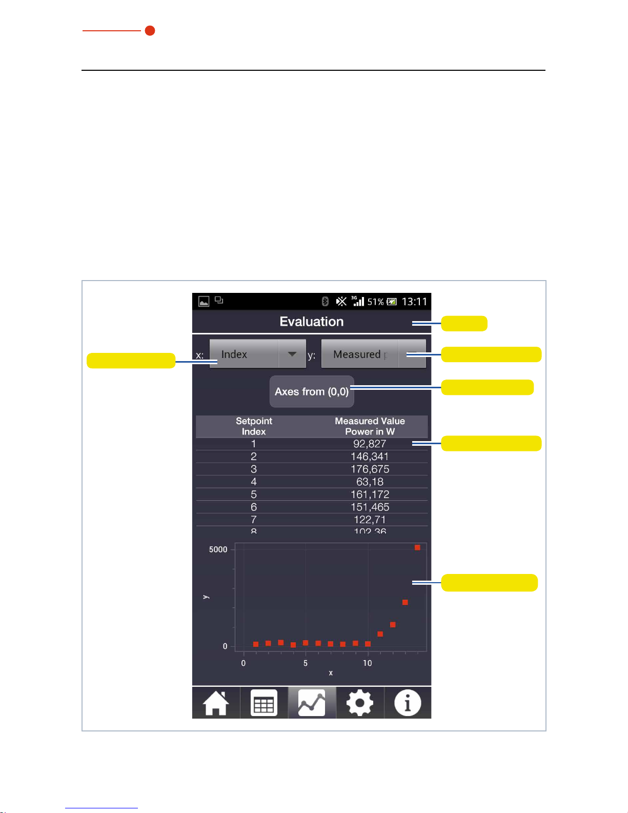
12.8.3 Evaluation
This page graphically displays select measured values or entire measurement series.
Selected setpoint values are displayed on the x-axis and measured values or the percentage of deviation of the measured values from the setpoint values are displayed on
the y-axis.
If setpoint values aren’t entered ahead of time, the measured values will also be entered
into the setpoint value list for graphic illustration. You can select either the power, pulse
length, or energy on both axes.
You can enlarge/shrink the view in the graph by pulling with two fingers.
Page
Selection y-axis
Axis scaling
Values numerically
Values graphically
Selection x-axis
Fig. 12.9: Evaluation

35,0(6
PowerMeasuringCassette PMC-C
29
Revision 01/2018 EN
If the minimum values are located in the upper or right part of the graph, you
can use the Axes from (0,0) button to shift the origin of the coordinate system
in order to optimize the display.
12.8.4 Devices
In the lower part of the page, you can configure various device settings, mainly to conserve power.
PMC-C 11267
Fig. 12.10: Devices

35,0(6
PowerMeasuringCassette PMC-C
30
Revision 01/2018 EN
Function Possible settings
Auto ready The device will automatically switch to be ready for the next mea-
surement by default. If you remove the check mark, you will have to
put the device back into ready mode after each measurement by
quickly pressing the activation button.
Energy-saving features Continuous background lighting on/off.
Turn off lighting after(in s). The set time only applies when continuous
background lighting is turned off.
Turn interlock on/off. For security reasons, it is not recommended
that you turn interlock off.
Turn the device off after a specified period of time.
Tab. 12.3: Functions
Every time you change the settings, you must tap on the Update button in order to
save the desired settings on the device (it may take a few minutes for the device to
accept the settings).

35,0(6
PowerMeasuringCassette PMC-C
31
Revision 01/2018 EN
12.8.5 Info
This page gives information, among other things, on the firmware and software versions used on the PRIMES measuring device. In the status area you will find any error
messages and warning notices or information on the status of the connection with the
device.
Regardless of which page you have selected, the navigation bar will alert you when a
status report has been released by displaying an exclamation point in the info icon
.
At the same time, the temperature display and info symbol on the Measuring opera-
tion page will be shown in red.
PMC-C 11267
Status notification
Info symbol
Fig. 12.11: Info

35,0(6
PowerMeasuringCassette PMC-C
32
Revision 01/2018 EN
Status reports
In order to prevent damage to the absorber, power levels and pulse lengths can be no more
than 8000W and 2000ms.
The energy input exceeds the maximum capacity of the absorber. Reduce the power and/or
pulse length.
The energy input exceeds the remaining capacity of the absorber. Reduce the power and/or
pulse length or wait until the absorber has cooled.
The current absorber temperature is over 70°C, wait until the absorber has cooled down
before you make another measurement.
The energy input is too low to obtain a reliable measuring result. Increase the power and/or
pulse length.
Tab. 12.4: Status reports

35,0(6
PowerMeasuringCassette PMC-C
33
Revision 01/2018 EN
13 Measuring and displaying with the PRIMES Cube App
13.1 Safety Instructions
CAUTION
Cutting hazard
Contamination and fingerprints on the protective window can lead to damage or shattering or splintering of the protective window during measuring operation.
X
Do not touch the protective window.
X
Regularly check the condition of the protective window and exchange it
in case of pollution (see chapter15.1, „Exchanging the protective window“, on page41).
X
Only operate the device with a clean protective window.
NOTICE
Damaging/Destruction of the device
The maximum permissible energy per laser pulse depends on various
variables, including the absorber temperature.
X
Please mind the limit values and dependencies given in chapter17,
„Technical data“, on page45 and chapter20, „Appendix“, on
page49 before performing the measurement.
NOTICE
Damage to the laser system
Contamination and fingerprints on the protective window can lead to
damage or shattering or splintering of the protective window during
measuring operation. Parts of the protective window can get into the
laser system and damage it.
X
Regularly check the condition of the protective window and exchange it
in case of pollution (see chapter15.1, „Exchanging the protective window“, on page41).
X
Only operate the device with a clean protective window.

35,0(6
PowerMeasuringCassette PMC-C
34
Revision 01/2018 EN
13.2 Laser parameter setting
13.2.1 Setting the laser rise time
The applicable measurement time is between 0.1 s and 2.0 s, which has to be transferred to the laser controller as pulse length. The maximum laser rise time for measuring the power cannot exceed 100 µs. This limit has to be adhered to in order to avoid
incorrect results of the power measurement.
Some laser beam sources are factory set with power ramps of up to a few 100 ms to
switch on the laser beam. To achieve the correct power values the shortest possible rise
time (< 100 μs) has to be set.
P
Max
P
Meas
t
t
p
t
0
P
100µs
Fig. 13.1: Laser rise time > 100µs
P
Max
≙ P
Meas
t
t
p
t
0
P
100µs
Fig. 13.2: Laser rise time < 100µs

35,0(6
PowerMeasuringCassette PMC-C
35
Revision 01/2018 EN
13.2.2 Minimum energy per single measurement
The energy used for the measurement must achieve a sufficiently high temperature in
the absorber to be recorded with high precision. Energy of about 300J is generally
recommended, as long as the measurement duration is < 2 s.
Example: With a laser power of 1kW and an irradiation time of 300ms, 300 J are
absorbed.
E = P · t = 1000W · 0.3s = 300J
Tab. 13.1 on page 35 shows information for selecting the energy permissible for a
measurement in conjunction with the absorber temperature.
25 30 35 40 45 50 55 60 65 70
Absorber temperature in °C
Permissible measuring energy in J
1000
3000
10
100
PWC - Messbereich in Abhängigkeit der Absorbertemperatur
25 °C Ambient temperature
Max. energy input
Min. energy input
The measuring range varies in accordance with the ambient
temperature. To achieve the greatest possible accuracy, the
absorber temperature should be close to the ambient temperature, particularly when it comes to the measurement of small
amounts of energy (< 200 J).
Tab. 13.1: Measuring range as a function of the absorber temperature
The minimum energy application shows the limit above which a measurement can be
performed with high precision. The maximum energy application value specifies the limit
at which the absorber reaches its reliable limit temperature. The energy, e.g. for multiple
measurements (series measurements) can be distributed across the range shown in
green.
If the absorber temperature is greater than 70 ˚C, it won’t be possible to take any further
measurements. In this case, please wait until the temperature falls to below 50°C (depending on the energy application selected). Please take the limit values from Tab. 13.1
on page 35.

35,0(6
PowerMeasuringCassette PMC-C
36
Revision 01/2018 EN
13.3 Prepare measurement
Please read chapter13.1, „Safety Instructions“, on page33 first.
X Tap the Cube icon to start the app.
Cube
X The Devices page is opened.
X Tap the Start Device Search
button.
The devices found are displayed.
PMC-C 11267
X Tap on the desired device in order
to establish a connection and confirm the query with OK.
PMC-C 11267
The bluetooth connection to the
device is displayed .
PMC-C 11267

35,0(6
PowerMeasuringCassette PMC-C
37
Revision 01/2018 EN
X Configure the desired device
settings and tap on Update.
X Switch to the Measuring opera-
tion page.
X Enter the desired power and pulse
length under Next measurement.
X Set the desired power and pulse
length on the laser.
For a high measurement accuracy, we recommend an energy input of 300J per measurement.
See chapter13.2.2, „Minimum energy per single
measurement“, on page35.
Observe the information on serial measurements
according to chapter 13.4 on page 38.
Note: The PRIMES measuring device and
PRIMES Cube App WILL NOT transfer any data
to the laser!

35,0(6
PowerMeasuringCassette PMC-C
38
Revision 01/2018 EN
13.4 Serial measurement
Please read chapter13.1, „Safety Instructions“, on page33 first.
Always start a measurement series with the smallest power and increase it gradually.
Small amounts of energy should be measured with absorber temperatures that are
close to the ambient temperature.
In general:
The minimum amount of irradiated energy should amount to approximately twenty times
the difference of the absorber temperature minus room temperature, so at least 50 J.
In case of subsequent measurements, the residual capacity of the absorber for another
laser pulse has to be considered. Tab. 13.2 on page 38 shows information for selecting the energy permissible for a series measurement in conjunction with the absorber
temperature.
25 30 35 40 45 50 55 60 65 70
Absorber temperature in °C
Permissible measuring energy in J
1000
3000
10
100
PWC - Messbereich in Abhängigkeit der Absorbertemperatur
1st measurement 50 J
2nd measurement 100 J
3rd measurement 300 J
4th measurement 600 J
5th measurement 900J
Max. energy input
Min. energy input
Tab. 13.2: Example of a series measurement in conjunction with the absorber temperature
If the absorber temperature is greater than 70 ˚C, it won’t be possible to take any further
measurements. In this case, please wait until the temperature falls to below 50°C (depending on the energy application selected). Please take the limit values from Tab. 13.2
on page 38.

35,0(6
PowerMeasuringCassette PMC-C
39
Revision 01/2018 EN
13.5 Measurement with pulsed lasers
Limited measurement with pulsed lasers is possible. When it comes to pulsed laser
radiation a correct exposure time measurement up to a pulse frequency of 1 kHz and a
duty cycle of 50 % is possible.
In case of on/off times shorter than 500 μs a correct exposure time measurement is not
possible.

35,0(6
PowerMeasuringCassette PMC-C
40
Revision 01/2018 EN
14 Measurement and evaluation with the LaserDiagnosticsSoft-
ware LDS
With the optional operating and evaluation software LaserDiagnosticsSoftware LDS you
can also operate the device via the PC and evaluate the measurements. The functions
can be found in Tab. 14.1 on page 40.
Function Possible Settings
Auto ready By default, the device automatically returns to measurement readi-
ness after each measurement. If you uncheck the box, you will need
to reset the unit after each measurement by briefly pressing the on/
of button.
Power Saving Function Continuous background on/off
Turn off backlight after (in s). The set time only applies if the permanent backlight is switched off.
Switch interlock on/off (no function on the PMC-C).
Switch off the device after an entered time
Tab. 14.1: Functions and settings

35,0(6
PowerMeasuringCassette PMC-C
41
Revision 01/2018 EN
15 Maintenance and service
The operator is responsible for determining the maintenance intervals for the measuring
device.
PRIMES recommends a maintenance interval of 12 months for inspection and validation
or calibration.
If the device is used only sporadically, the maintenance interval can also be extended up
to 24 months.
15.1 Exchanging the protective window
The protective window in the beam entrance is a wearing part and can be replaced
if necessary. Low levels of contamination of the protective window can be carefully
removed when cooled with Isopropanol (observe the manufacturer‘s safety instructions).
In case of heavy, non-removable contamination or damage, the protective window must
be replaced with a new one.
The protective window is coated with an antireflection coating and has low
reflection values of less than 1%. To avoid increased reflection values, use only
original PRIMES protective window.
Protective window diameter 55mm
Glass thickness 1.5mm
Order number 410-070-021 (1 piece); 410-070-031 (10 pieces)
15.1.1 Safety instructions
CAUTION
Burns due to hot components
After a measurement the absorber below the protective window is hot!
Unintentional contact during the protective window exchange could lead
to burns.
X
Do not replace the protective window directly after a measurement.
X
Let the device cool down for an adequate period of time. The cooling
time varies depending on the laser power and the irradiation time.

35,0(6
PowerMeasuringCassette PMC-C
42
Revision 01/2018 EN
CAUTION
Cutting hazard
Contamination and fingerprints on the protective window can lead to damage or shattering or splintering of the protective window during measuring operation.
X
Only replace the protective window in a dust-free environment.
X
Do not touch the protective window.
X
When exchanging the protective window, always wear cotton- or powderfree latex gloves.
NOTICE
Damage to the laser system
Contamination and fingerprints on the protective window can lead to
damage or shattering or splintering of the protective window during
measuring operation. Parts of the protective window can get into the
laser system and damage it.
X
Only replace the protective window in a dust-free environment.
X
Do not touch the protective window.
X
When exchanging the protective window, always wear cotton- or powderfree latex gloves.

35,0(6
PowerMeasuringCassette PMC-C
43
Revision 01/2018 EN
1. Observe the safety instructions in chapter 15.1.1 on page 41.
2. Unscrew the 4 Torx screws M3 x 8 mm on the protective window holder.
3. Place the device as shown in Fig. 15.1 on page 43 and carefully remove the
protective window holder upwards.
• Make sure that the inserted Teflon cord and the mirror do not fall out of the device.
4. Remove old protective window from the device and dispose of it.
5. Wear cotton or powder-free latex gloves and insert new protective window into
the device.
• Ensure that the inserted Teflon cord and the mirror is not out of place.
6. Place the protective window holder according to Fig. 15.1 on page 43 with the
2 recesses towards the front.
7. Tighten the protective window holder with 4 Torx screws M3 x 8 mm.
8. Check for secure fit of the protective window holder:
• The protective window holder must lie flat against the device.
Torx screws
M3 x 8 mm
Protective window
holder
Protective
window
Mirror
Teflon cord
2 Recesses
Fig. 15.1: Exchanging the Protective Window

35,0(6
PowerMeasuringCassette PMC-C
44
Revision 01/2018 EN
16 Measures for the product disposal
Due to the Electrical and Electronic Equipment Act (“Elektro-G“) PRIMES is obliged to
dispose PRIMES measuring devices manufactured after August, 2005, free of charge. PRIMES is a registered manufacturer in the German “Used Appliances Register“
(Elektro-Altgeräte-Register “EAR“) with the number WEEE-reg.-no. DE65549202.
Provided that you are located in the EU, you are welcome to send your PRIMES devices
to the following address, where they will be disposed free of charge (this service does
not include shipping costs):
PRIMES GmbH
Max-Planck-Str. 2
64319 Pfungstadt
Deutschland

35,0(6
PowerMeasuringCassette PMC-C
45
Revision 01/2018 EN
17 Technical data
Measurement Parameters
Beam dimensions 10 – 30 mm
Power range 400 – 8000 W
1)
Wavelength range 900 – 1090 nm
Irradiation time 0.1 – 1 s
1)
(depending on the laser power)
Nominal measuring frequency 400 J: 1 cycle / min;
3000 J: 1 cycle /15 min
Accuracy ± 3 %
Reproducibility ± 1 %
1)
The stated limit values are to be understood in correlation with the permitted maximum energy
(E = P · t).
Limit Values
Max. absorber temperature 120 °C
Energy per measurement 50 – 3000 J
Recommended energy per measurement 300 – 500 J
Max. power density
(peak) on the absorber
(approx. 2 mm underneath the protective window) at beam diameters
> 10mm 1,5 kW / cm²
10mm – 3mm 2,5 kW / cm²
3mm – 1.5mm 5 kW / cm²
1.5mm – 1mm 6 kW / cm²
< 1mm 8 kW / cm²
Max. laser rise time 100 µs
Max. angle of incidence ± 5
°

35,0(6
PowerMeasuringCassette PMC-C
46
Revision 01/2018 EN
Supply Data
Power supply Integrated lithium-ion battery, which can be
charged via a micro-USB port
Temperature range for charging the lithiumIon battery
0 °C up to +45 °C
Communication
Interfaces USB / Bluetooth
Dimensions and Weight
Dimensions (L x W x H) 100 x 76 x 31 mm
Weight (approx.) 350 g
Environmental Conditions
Operating temperature range 10 – 40 °C
Storage temperature range 5 – 50 °C
Reference temperature 22 °C
Permissible relative humidity
(non-condensing)
10 – 80 %

35,0(6
PowerMeasuringCassette PMC-C
47
Revision 01/2018 EN
18 Dimensions
All dimensions in mm (general tolerance ISO 2768-v)

35,0(6
PowerMeasuringCassette PMC-C
48
Revision 01/2018 EN
19 Declaration of conformity

35,0(6
PowerMeasuringCassette PMC-C
49
Revision 01/2018 EN
20 Appendix
20.1 Max. laser power depending on the irradiation time
0
1000
2000
3000
4000
5000
6000
7000
8000
9000
0 0,2 0,4 0,6 0,8 1 1,2
Irradiation time in s
Laser power in W
20.2 Max. laser power depending on the beam diameter
0
1000
2000
3000
4000
5000
6000
7000
8000
9000
0 5 10 15 20 25 30 35
Beam diameter in mm
Laser power in W

35,0(6
PowerMeasuringCassette PMC-C
50
Revision 01/2018 EN

35,0(6
PowerMeasuringCassette PMC-C
51
Revision 01/2018 EN

PRIMES GmbH
Max-Planck-Str. 2
64319 Pfungstadt
Deutschland
Telephone: +49 6157 9878-0
info@primes.de
www.primes.de
 Loading...