


Revision 01/2018 EN
FocusMonitor FMW+
Additional Documentation to the Operating Manual
FocusMonitor FM+
35,0(6
Short Start Guide
Translation of the Original Instructions


FocusMonitor FMW+
3
Revision 01/2018 EN
35,0(6
IMPORTANT!
READ CAREFULLY BEFORE USE.
KEEP FOR FUTURE USE.

FocusMonitor FMW+
4
Revision 01/2018 EN
35,0(6
Contents
1 About this documentation 5
2 Distinguishing features in comparison with the standard device 5
3 Connections 5
4 Status display 6
5 Adapt device 6
5.1 Inserting the measuring tip ........................................................................................................7
6 Hinweise zum Absorber 9
7 Mounting/Dismounting 9
7.1 Installation position ....................................................................................................................9
7.2 Alignment ..................................................................................................................................9
8 Electrical connection 10
8.1 Connection to the PC/LAN and establishing the power supply ................................................10
9 Measuring with the LaserDiagnosticsSoftware LDS 11
9.1 Single plane measurement ......................................................................................................11
9.2 Caustic measurement .............................................................................................................15
9.3 Measuring mode Monitor ......................................................................................................20
10 Declaration of conformity 24
11 Technical data 25
12 Dimensions 26
13 Appendix 27
13.1 Exchanging the measuring tip ................................................................................................27
13.2 Exchanging the detector .........................................................................................................29

FocusMonitor FMW+
5
Revision 01/2018 EN
35,0(6
1 About this documentation
This documentation describes the special version „FocusMonitor FMW+“ of the PRIMES measuring device
“FocusMonitor FM+” and presents the differences. It supplements the standard operating manual of the
FocusMonitor FM+.
IMPORTANT!
Please pay special attention to the safety instructions given in the standard operating manual of the
FocusMonitor FM+.
2 Distinguishing features in comparison with the standard device
• The FocusMonitor FMW+ does not have an integrated z-axis. For the measurement the focus is moved
along the axis by the system. Information regarding the z-position can either be entered manually via the
settings dialogue (measurement >> single measurement) in the LaserDiagnosticsSoftware.
• An absorber is integrated into the measuring device (maximum absorber power of 1000 watts).
• The maximum energy per measurement is 90kJ (max. irradiation time=90s at 1000Watt).
• The measuring device does not have a protective gas connection
• Direct connection to the PC via Ethernet.
3 Connections
LED display
On/off switch
Ethernet connection RJ-45
Power supply connection
Fig. 3.1: Connections of the FMW+

FocusMonitor FMW+
6
Revision 01/2018 EN
35,0(6
4 Status display
The different operating modes are indicated by three LEDs.
Designation Color Meaning
Measuring Red Measurement is running
Rotation Orange Motor is running
Power White Voltage is applied (24V)
5 Adapt device
Depending on the laser type the corresponding measuring tip and a suitable detector have to be used. The
DFIG-PS+ detector is included ex works; the measuring tip has to be mounted by the customer.
Detector
type
Laser Type of Sensor Amplification Wavelength range in μm
DFC+ CO
2 Pyro-detector 1 9 − 12
DFY-PS+ NIR/VIS Photodiode Automatic adaptation of the sensitivity 0.4 − 1.1
DFIG-PS+ NIR Photodiode Automatic adaptation of the sensitivity 1 − 2.1
Tab. 5.1: Variety of detectors
Measuring tip High Power CO
2
High Div YAG Diode Tip
Typical pin hole diameter in µm 20-25 20 50
Beam divergence/acceptance angle in mrad < 240 < 200 < 500
Typical wavelength in µm 9-12 0.4-1.1 0.4-1.0
CO
2
Laser
Max. power density
*
)
in MW/cm2
30 — —
Max. power in kW 1 — —
Nd:YAG Laser
Max. power density
*
)
in MW/cm
2
— 10 1
Max. power in kW — 1 1
Diode Laser
Max. power density in MW/cm
2
— 1 1
Suitable Detectors
Detector type DFC+ DFIG-PS+, DFY-PS+ DFIG-PS+, DFY-PS+
Tab. 5.2: Variety of measurement tips and detectors
*) Please note the damage threshold in the Operating Manual FocusMonitor FM+.

FocusMonitor FMW+
7
Revision 01/2018 EN
35,0(6
5.1 Inserting the measuring tip
To prevent transport damage, the measuring tip is disassembled when delivered. It is to be installed with the
curved part facing towards the beam source.
There are different measurement tips available for different wavelengths (see Tab. 5.2 on page6).
NOTICE
Danger of damaging the measuring tip
The small drill hole in the measuring tip can be blocked easily by dirt particles or by
touching it with bare hands.
When mounting/dismounting the tip, please wear powder-free latex gloves and ensure a
dirt- and dust-free environment.
1. Turn off the supply voltage.
2. Turn the drive wheel (see Fig. 5.4) clockwise until the disc extends approx. 15mm into the measuring
window in a positive y-direction.
Drive wheel
Disc with measuring tip retaner
Fig. 5.1: Moving the disc into the measuring window
3. Turn the disc until the measuring tip retainer becomes visible in the opening of the housing.
4. Remove the fastening screws (Torx T8) as well as the retaining plate.
5. Carefully insert the new measuring tip in the disc (caution, the entrance aperture is located on the arched
side of the tip, see Fig. 5.2).

FocusMonitor FMW+
8
Revision 01/2018 EN
35,0(6
Entrance aperture
Fig. 5.2: Entrance aperture (pinhole) in the measuring tip
Fig. 5.3: Inserting the measuring tip
6. Insert the retaining plate in the disc with the guidance groove pointing upwards and an angle of 45 degrees and press it downwards into the opening (see Fig. 5.4).
Fig. 5.4: Inserting the retaining plate
7. Insert the screws and fasten them hand-tight.
8. Move the measuring tip out of the measuring window to ensure it is protected.
When turning the supply voltage back on, the measuring head automatically moves back into its
resting position.

FocusMonitor FMW+
9
Revision 01/2018 EN
35,0(6
6 Notes on the absorber
The high-power absorber can absorb an energy application of 90 kJ (1000 W · 90 s).
NOTICE
Risk of damage caused by overheating
The absorber is equipped with an alarm siren that warns of overheating. It activates when
the absorber casing reaches a temperature of 60 °C.
In case of alarm, immediately turn off the laser and allow the absorber to cool!
NOTICE
Risk of burns
The laser beam can make the surface of the absorber very hot.
Do not touch the absorber during or immediately after a measurement!
7 Mounting/Dismounting
7.1 Installation position
The FMW+ was designed for a vertical beam incidence from above.
7.2 Alignment
1. When positioning the device in x- and y- direction,
please make sure that the laser beam hits the
center of the semi-circle in the inlet aperture.
Air in
Air out
Power
Position of the laser beam

FocusMonitor FMW+
10
Revision 01/2018 EN
35,0(6
8 Electrical connection
The FMW+ requires a voltage supply of 24VDC for the operation. A suitable power supply is included in the
scope of delivery. Use only the included cable to connect the power supply with the local power supply.
Data is transmitted between the FocusMonitor FMW+ and PC/LAN via the Ethernet connection.
8.1 Connection to the PC/LAN and establishing the power supply
Offset: 10.6 mm
Measuring
Rotation
Power
x
+
-
+
y
FMW
+
FocusMonitor
Ethernet
Power In
Ethernet crossover cable
Ethernet
PC
FMW+
PRIMES power supply
Fig. 8.1: Connection of FMW+
Connect the FMW+ to the PC via a crossover cable or to the network via a patch cable.

FocusMonitor FMW+
11
Revision 01/2018 EN
35,0(6
9 Measuring with the LaserDiagnosticsSoftware LDS
With the FocusMonitor FMW+, you can measure one or more planes. Since the FocusMonitor FMW+ does
not have its own mobile z-axis, the system must move the focusing lens or the device in this direction when
measuring multiple planes.
You will find detailed explanations concerning the settings and measuring mode in the operating manuals of
the FM+ and LaserDiagnosticsSoftware LDS.
9.1 Single plane measurement
9.1.1 Connect the device with the LaserDiagnosticsSoftware LDS
1. Switch on the FocusMonitor FMW+.
The operating mode is shown in
the status display (see chapter 4 on
page6).
2. Start the LaserDiagnosticsSoftware
LDS.
3. Click on the Devices tab.
4. Click on the + Connect to device
button under the tab.
The Connections window appears.
5. Click on the desired device.
6. Click on the Connect to device button.
The FocusMonitor FMW+ is estab-
lished as a connected device.
7. Click on the Scanner function.
The Device control menu opens.
Function Scanner
Device control

FocusMonitor FMW+
12
Revision 01/2018 EN
35,0(6
9.1.2 Selecting the measuring mode Single planes
1. In the Device control click on the
Measuring mode drop-down list.
2. Click on the entry Single planes.
Dropdown list Measuring mode
Measuring mode Single planes
The corresponding Device control
opens.
The Single planes toolbench opens
wit the tools Caustic analysis and
Plane analysis.
Caustic analysis Plane analysis
9.1.3 Configuring the settings (Device control > Settings)
1. Click on the Settings tab.
2. Enter the desired manual z-Position
in mm.
3. Activate the check box autom. Mea-
surement window.
4. Activate the check box autom. Gain.
• Please keep in mind that automatic
amplification is not available with the
CO
2
detector.
Only when measuring a time series
5. Enter the number of measurements.
6. Enter the measuring break between
automatic caustic measurements in s.
FocusMonitor FMW+
13
Revision 01/2018 EN
35,0(6
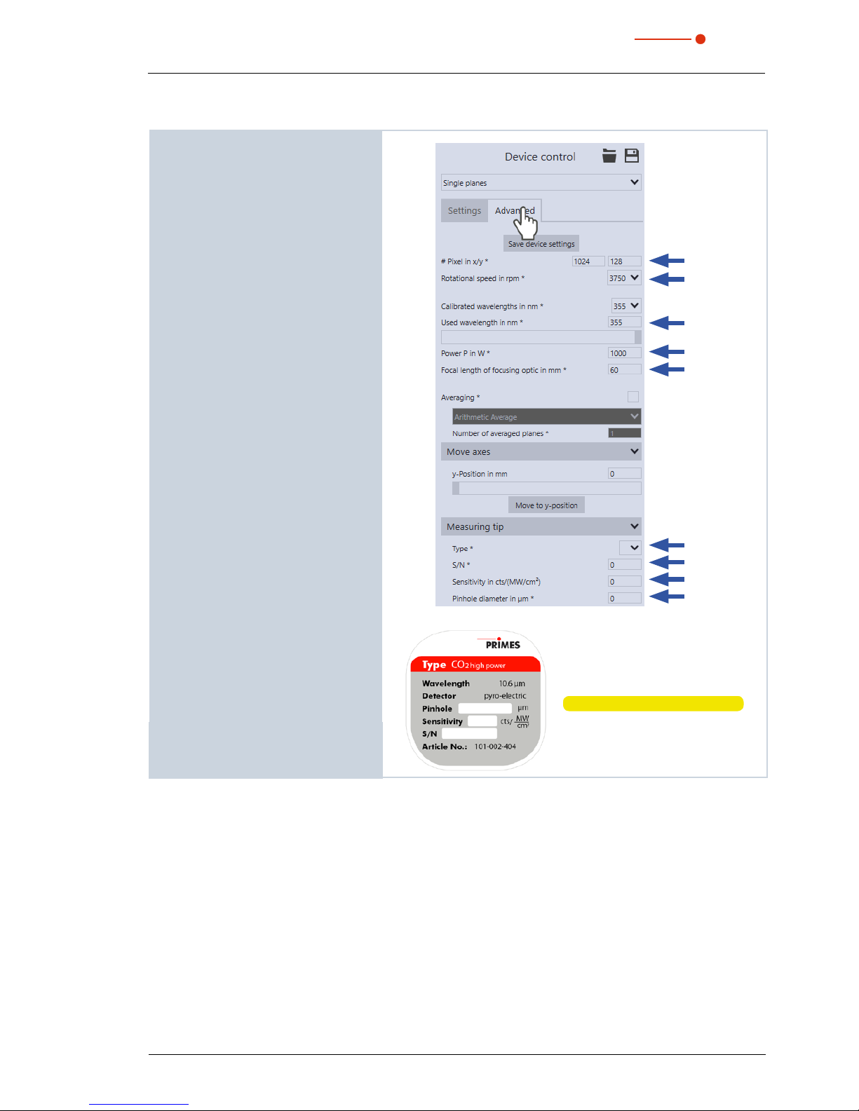
9.1.4 Configuring advanced settings (Device control > Advanced)
1. Click on the Advanced tab.
2. Enter the number of pixels in the
x/y-direction in order to configure the
resolution.
3. Select the rotation speed of the measuring tip 1875, 3750 or 7500rpm.
4. Enter the used wave length in nm.
5. Enter the laser power in Watt.
6. Enter the focal length of the focusing
optic in mm.
Move axis
With FocusMonitor FMW+, it is only possible to move along the y-axis.
• More detailed information
can be found in the manual
„LaserDiagnosticsSoftware LDS“.
Measuring tip
You will find the entry values on the label
attached to the packaging of the measuring tip used.
7. Select the type of measuring tip used.
8. Enter the serial number S/N of the
measuring tip.
9. Enter the sensitivity of the measuring
tip used in cts/(MW/cm²).
10. Enter the pinhole diameter of the
measuring tip used.
Label with measuring tip data

FocusMonitor FMW+
14
Revision 01/2018 EN
35,0(6
9.1.5 Starting measurement
1. Follow the safety instructions in the
Operating Manual „FocusMonitor
FM+“.
2. Turn on the laser.
3. Click on the Start button.
The progress of the measurement is
indicated in the status window below
the start/stop control panel.
9.1.6 Terminating measurement
In the status window below the Start/
Stop operating panel, Measuring
completed is displayed.
1. Press the Stop Rotation button.
2. Turn off the laser.
9.1.7 Measuring results display
The measuring results are displayed in the opened tools once the measurement has been completed.
Fig. 9.1: Measuring results in the opened tools

FocusMonitor FMW+
15
Revision 01/2018 EN
35,0(6
9.2 Caustic measurement
Since the FocusMonitor FMW+ does not have its own z-axis to move along, the system must move either
the device or focusing lens in this direction in order to measure the caustic.
You can enter each new z-position manually and start it manually or specify a z-increment with equidistant
offsets.
9.2.1 Checking the Alignment with the LaserDiagnosticsSoftware LDS
1. Switch on the FocusMonitor FMW+.
The operating mode is shown in
the status display (see chapter on
page4).
2. Start the LaserDiagnosticsSoftware
LDS.
3. Click on the Devices tab.
4. Click on the + Connect to device
button under the tab.
The Connections window appears.
5. Click on the desired device.
6. Click on the Connect to device button.
The FocusMonitor FMW+ is estab-
lished as a connected device.
7. Click on the Scanner function.
The Device control menu opens.
Function Scanner
Device control

FocusMonitor FMW+
16
Revision 01/2018 EN
35,0(6
9.2.2 Selecting the measuring mode Single planes
1. In the Device control click on the
Measuring mode drop-down list.
2. Click on the entry Single planes.
Dropdown list Measuring mode
Measuring mode Single planes
The corresponding Device control
opens.
The Single planes toolbench opens
wit the tools Caustic analysis and
Plane analysis.
9.2.3 Configuring the settings (Device control > Settings)
1. Click on the Settings tab.
2. Enter the desired z-increment in mm.
3. Enter the desired manual z-Position
in mm.
4. Activate the check box autom. Mea-
surement window.
5. Activate the check box autom. Gain.
• Please keep in mind that automatic
amplification is not available with the
CO
2
detector.
Only when measuring a time series
6. Enter the number of measurements.
7. Enter the measuring break between
automatic caustic measurements in s.

FocusMonitor FMW+
17
Revision 01/2018 EN
35,0(6
9.2.4 Configuring advanced settings (Device control > Advanced)
1. Click on the Advanced tab.
2. Enter the number of pixels in the
x/y-direction in order to configure the
resolution.
3. Select the rotation speed of the measuring tip 1875, 3750 or 7500rpm.
4. Enter the used wave length in nm.
5. Enter the laser power in Watt.
6. Enter the focal length of the focusing
optic in mm.
Move axis
With FocusMonitor FMW+, it is only possible to move along the y-axis.
• More detailed information
can be found in the manual
„LaserDiagnosticsSoftware LDS“.
Measuring tip
You will find the entry values on the label
attached to the packaging of the measuring tip used.
7. Select the type of measuring tip used.
8. Enter the serial number S/N of the
measuring tip.
9. Enter the sensitivity of the measuring
tip used in cts/(MW/cm²).
10. Enter the pinhole diameter of the
measuring tip used.
Label with measuring tip data

FocusMonitor FMW+
18
Revision 01/2018 EN
35,0(6
9.2.5 Starting caustic measurement
1. Follow the safety instructions in the
Operating Manual „FocusMonitor
FM+“.
2. Turn on the laser.
3. Click on the Start button.
The progress of the measurement is
indicated in the status window below
the start/stop control panel.
9.2.6 Measuring next plane
1. As soon as the Measurement completed status notification appears,
you can measure the next plane.
1. Click on the Settings tab.
2. Enter the desired offset in mm in the
z-Increment field.
3. Enter the desired start position in mm
in the z-position field.
4. As soon as the Measurement com-
pleted status notification appears,
click on Start again.
5. Repeat this process until the desired
number of planes has been achieved.

FocusMonitor FMW+
19
Revision 01/2018 EN
35,0(6
9.2.7 Terminating caustic measurement
X Click on the Stop button.
X Turn off the laser.
In the status window below the Start/
Stop operating panel, Measuring
completed is displayed.
9.2.8 Measuring results display
The measuring results are displayed in the opened tools once the measurement has been completed.
Fig. 9.2: Measuring results in the tools

FocusMonitor FMW+
20
Revision 01/2018 EN
35,0(6
9.3 Measuring mode Monitor
Monitor measuring mode was meant to be used to make adjustments. Data is not determined in this measuring mode, but rather only the desired plane is shown in false-colors.
9.3.1 Checking the Alignment with the LaserDiagnosticsSoftware LDS
1. Switch on the FocusMonitor FMW+.
The operating mode is shown in
the status display (see chapter 4 on
page6).
2. Start the LaserDiagnosticsSoftware
LDS.
3. Click on the Devices tab.
4. Click on the + Connect to device
button under the tab.
The Connections window appears.
5. Click on the desired device.
6. Click on the Connect to device button.
The FocusMonitor FMW+ is estab-
lished as a connected device.
7. Click on the Scanner function.
The Device control menu opens.
Function Scanner
Device control

FocusMonitor FMW+
21
Revision 01/2018 EN
35,0(6
9.3.2 Selecting the measuring mode Monitor
1. In the Device control click on the
Measuring mode drop-down list.
2. Click on the entry Monitor.
Drop down list Measuring mode
Measuring mode Monitor
The corresponding Device control
opens.
The Monitor toolbench opens wit the
tool False color image.
9.3.3 Configuring the settings (Device control > Settings))
1. Click on the Settings tab.
2. Enter the desired z-Position in mm.
3. Enter the desired gain in dB.

FocusMonitor FMW+
22
Revision 01/2018 EN
35,0(6
9.3.4 Configuring advanced settings (Device control > Advanced)
1. Click on the Advanced tab.
2. Select the rotation speed of the measuring tip 1875, 3750 or 7500rpm.
3. Enter the number of pixels in the
x/y-direction in order to configure the
resolution.
4. Enter the used wave length in nm.
5. Enter the laser power in Watt.
6. Enter the focal length of the focusing
optic in mm.
Move axis
These settings are not relevant to the
Monitor measuring mode.
Measuring tip
You will find the entry values on the label
attached to the packaging of the measuring tip used.
7. Select the type of measuring tip used.
8. Enter the serial number S/N of the
measuring tip.
9. Enter the sensitivity of the measuring
tip used in cts/(MW/cm²).
10. Enter the pinhole diameter of the
measuring tip used.
Label with measuring tip data

FocusMonitor FMW+
23
Revision 01/2018 EN
35,0(6
9.3.5 Starting measuring mode Monitor
1. Follow the safety instructions in the
Operating Manual „FocusMonitor
FM+“.
2. Turn on the laser.
3. Click on the Start button.
The selected planes are continu-
ally scanned in the x-y direction and
shown in the False color view tool.
9.3.6 Terminating measuring mode Monitor
1. Click on the Stop button.
2. Turn off the laser.
In the status window below the Start/
Stop operating panel, Measurement
completed is displayed.

FocusMonitor FMW+
24
Revision 01/2018 EN
35,0(6
10 Declaration of conformity

FocusMonitor FMW+
25
Revision 01/2018 EN
35,0(6
11 Technical data
Measurement parameters
Power range up to 1000W
Max. energy per measurement 90 kJ
Wavelength range 0.4 – 12 µm
Beam dimensions, typ. 150 – 3000 µm (optionally up to 5000 µm)
Function of the measuring system
Measurement window sizes 0.08 x 0.08 up to 8 x 8 mm
Optionally 0.08 x 0.08 up to 12 x 24 mm (at 64 pixel resolution)
Resolution 32 x 32 – 256 x 256 pixel
Rotation speed 1875, 3750 rpm
Supply data
Power supply 24 V DC ± 5 %, max. 1.8 A
Communication
Interfaces Ethernet
Dimensions and weight
Dimensions (L x W x H)
Height with the carrying handle folded down
185.5 x 153 x 237.5 mm
208.5mm
Weight, approx. 8 kg
Environmental conditions
Operating temperature range +10°C up to +40°C
Permissible relative humidity (non-condensing)
10 – 80%

FocusMonitor FMW+
26
Revision 01/2018 EN
35,0(6
12 Dimensions
All dimensions in mm (general tolerance ISO 2768-v)

FocusMonitor FMW+
27
Revision 01/2018 EN
35,0(6
13 Appendix
13.1 Exchanging the measuring tip
There are different measurement tips available for different wavelengths (see „Tab. 5.2: Variety of measurement tips and detectors“ on page6).
NOTICE
Danger of damaging the measuring tip
The small drill hole in the measuring tip can be blocked easily by dirt particles or by touching it with bare hands.
When mounting/dismounting the tip, please wear powder-free latex gloves and ensure a
dirt- and dust-free environment.
1. Turn off the supply voltage.
2. Turn the drive wheel (see Fig. 13.1) clockwise until the disc extends approx. 15mm into the measuring
window in a positive y-direction.
Drive wheel
Measuring tip retaner
Fig. 13.1: Moving the disc into the measuring window
3. Turn the disc until the measuring tip retainer becomes visible in the opening of the housing.
4. Remove the fastening screws (Torx T8) as well as the retaining plate.
5. Carefully insert the new measuring tip in the disc (caution, the entrance aperture is located on the arched
side of the tip, see Fig. 13.2).

FocusMonitor FMW+
28
Revision 01/2018 EN
35,0(6
Entrance aperture
Fig. 13.2: Entrance aperture (pinhole) in the measuring tip.
Fig. 13.3: Inserting the measuring tip
6. Insert the retaining plate in the disc with the guidance groove pointing upwards and an angle of 45 degrees and press it downwards into the opening (see Fig. 13.4).
Fig. 13.4: Inserting the retaining plate
7. Insert the screws and fasten them hand-tight.
8. Move the measuring tip out of the measuring window to ensure it is protected.
When turning the supply voltage back on, the measuring head automatically moves back into its
standby position.

FocusMonitor FMW+
29
Revision 01/2018 EN
35,0(6
13.2 Exchanging the detector
The NIR detector is the standard detector of the FMW+. For measurements with a CO2 laser the detector
has to be replaced by a CO2 detector.
NOTICE
Danger of damage for the detector sensor
The detector sensor must not be damaged and has to be protected from pollution.
Do not touch the detector sensor with your fingers and do not put it down on the sensor
surface.
Only use insulating plastic screws to fasten the detector to prevent noise signals. Do not forget the
foam rubber plate, otherwise the disc may be mechanically blocked by the screws.
Mounting sequence:
1. Turn off the supply voltage
2. Turn the drive wheel anti-clockwise as long as
possible. Now the detector is in its dismounting
position.
3. Carefully remove the two plugs from the detector,
for example by means of long nose pliers.

FocusMonitor FMW+
30
Revision 01/2018 EN
35,0(6
4. Remove the fastening screws on both sides of the
bottom plate (please mind that the screws have
different lengths).
5. Tilt the housing backwards.

FocusMonitor FMW+
31
Revision 01/2018 EN
35,0(6
6. Opened FMW+.
Detektor
7. Remove the plastic retaining screws of the detector with the short screw driver (included in the
scope of delivery) and carefully take the detector
out of the housing.

FocusMonitor FMW+
32
Revision 01/2018 EN
35,0(6
8. Build in the new detector in reversed order. Make
sure you do not forget the foam rubber spacer!
Attention!
If the screws are tightened too firmly, they might
block the rotary disc! Only tighten the screws
hand-tight. The foam rubber spacer may not be
compressed by more than 50% of its original
thickness!
Foam rubber spacer
Detector
x
x
2
Max.
Before
After
Foam Rubber Spacer
 Loading...