


35,0(6
Operating Manual
Translation of the original instructions
Cube L1
LaserDiagnosticsSoftware LDS
Cube App
Revision 01/2019 EN


35,0(6
Cube L1
IMPORTANT!
READ CAREFULLY BEFORE USE.
KEEP FOR FUTURE USE.
Revision 01/2019 EN
3

35,0(6
Cube L1
Table of contents
1 Basic safety instructions 8
2 Symbol explanation 10
3 About this operating manual 11
4 Conditions at the installation site 11
5 Important information for devices with rechargeable lithium-ion battery 12
5.1 Charging the battery ............................................................................ 12
5.2 Storing the battery ............................................................................... 12
5.3 If the battery is damaged ..................................................................... 12
5.4 Disposing of the battery ....................................................................... 12
6 System description 13
6.1 Measuring principles ............................................................................ 13
7 Transportation 13
8 Installation/Removal 14
8.1 Prepare installation ............................................................................... 14
8.2 Mounting position ................................................................................ 15
8.2.1 Align the Cube L1 with the alignment tool ............................... 16
8.3 Install the Cube L1 ............................................................................... 17
8.4 Remove the Cube L1 ........................................................................... 18
9 Connections 19
9.1 Safety interlock .................................................................................... 19
9.2 Micro-USB socket ............................................................................... 20
9.3 Bluetooth ............................................................................................. 20
10 Control elements 21
10.1 On/Off button ....................................................................................... 21
4
Revision 01/2019 EN

35,0(6
Cube L1
11 Display on the Cube L1 21
11.1 Status messages ................................................................................. 22
11.2 Warning message ................................................................................ 22
11.3 Capacity of the rechargeable lithium ion battery ................................... 22
12 Important information for measuring with the Cube L1 23
12.1 Safety instructions................................................................................ 23
12.2 Laser parameter setting ....................................................................... 24
12.2.1 Setting the laser rise time ....................................................... 24
12.2.2 Minimum energy per single measurement............................... 25
12.3 Series measurement ............................................................................ 26
12.4 Measurement with pulsed lasers .......................................................... 27
13 Measuring with the Cube L1 28
13.1 Start measurement .............................................................................. 28
13.2 Measuring results display ..................................................................... 30
14 Measuring with the optional LaserDiagnosticsSoftware LDS 31
14.1 Connect the Cube L1 with the LaserDiagnosticsSoftware LDS ............ 31
14.2 Select measurement mode CW Operation or Pulse Operation ............. 32
14.3 Make settings for power saving functions and automatic
measurement readiness ....................................................................... 33
14.4 Start measurement .............................................................................. 34
14.5 Measuring results display ..................................................................... 35
14.5.1 Displays in the toolbench CW Measurement or
Pulse Measurement ................................................................ 35
14.5.2 Displays in the toolbench Cube series ................................... 36
14.6 Load and delete measuring values ....................................................... 37
15 Measuring with the optional Cube App 38
Revision 01/2019 EN
5
35,0(6
Cube L1
16 Maintenance and service 39
16.1 Exchanging the protective window on the device ................................. 39
16.1.1 Safety instructions .................................................................. 39
16.1.2 Exchanging the protective window ......................................... 41
17 Measures for the product disposal 42
18 Declaration of conformity 43
19 Technical data 44
20 Dimensions 46
21 Appendix 47
21.1 System control (option) ........................................................................ 47
6
Revision 01/2019 EN

35,0(6
Cube L1
PRIMES - The Company
PRIMES manufactures measuring devices used to analyze laser beams. These devices
are employed for the diagnostics of high-power lasers ranging from CO
solid-state lasers to diode lasers. A wavelength range from infrared through to near UV
is covered, offering a wide variety of measuring devices to determine the following beam
parameters:
• Laser power
• Beam dimensions and position of an unfocused beam
• Beam dimensions and position of a focused beam
• Beam quality factor M²
PRIMES is responsible for both the development, production, and calibration of the
measuring devices. This guarantees optimum quality, excellent service, and a short reaction time, providing the basis for us to meet all of our customers’ requirements quickly
and reliably.
lasers and
2
PRIMES GmbH
Max-Planck-Str. 2
64319 Pfungstadt
Germany
Tel +49 6157 9878-0
info@primes.de
www.primes.de
Revision 01/2019 EN
7

35,0(6
Cube L1
1 Basic safety instructions
Intended use
The Cube L1 is used to measure power in the beam path of lasers. Please observe and
adhere to the specifications and limit values given in chapter19, „Technical data“, on
page44. Other forms of usage are improper. The information contained in this operating manual must be strictly observed to ensure proper use of the device.
Measurements with the CubeL1 should be performed exclusively with a static (unmoving) laser beam. While crossing over the absorber structure, moving beams can
produce faulty measurements during the exposure time, thus also producing the associated faulty power measurements.
Using the device for unspecified use is strictly prohibited by the manufacturer. By usage
other than intended the device can be damaged or destroyed. This poses an increased
health hazard up to fatal injuries. When operating the device, it must be ensured that
there are no potential hazards to human health.
The device itself does not emit any laser radiation. During the measurement, however, the laser beam is guided onto the device which causes reflected radiation (laser
class4). That is why the applying safety regulations are to be observed and necessary
protective measures need to be taken.
In measuring mode, the laser control’s safety interlock must be connected with the
device.
Observing applicable safety regulations
Please observe valid national and international safety regulations as stipulated in ISO/
CEN/TR standards as well as in the IEC-60825-1 regulation, in ANSIZ136 “Laser
Safety Standards” and ANSIZ136.1 “Safe Use of Lasers”, published by the American
National Standards Institute, and additional publications, such as the “Laser Safety
Basics”, the “LIA Laser Safety Guide”, the “Guide for the Selection of Laser Eye Protection” and the “Laser Safety Bulletin”, published by the Laser Institute of America, as well
as the “Guide of Control of Laser Hazards” by ACGIH.
Taking necessary safety measures
If there are people present within the danger zone of visible or invisible laser radiation,
for example near laser systems that are only partly covered, open beam guidance systems or laser processing areas, the following safety measures need to be taken:
8
Revision 01/2019 EN

35,0(6
Cube L1
• Connect the laser control’s safety interlock to the device. Check that the safety
interlock will switch off the laser properly in case of error.
• Please wear safety goggles adapted to the power, power density, laser wave
length and operating mode of the laser beam source in use.
• Depending on the laser source, it may be necessary to wear suitable protective
clothing or protective gloves.
• Please protect yourself from direct laser radiation, scattered radiation as well as
from beams generated from laser radiation (e.g. by using appropriate shielding
walls or by weakening the radiation to a harmless level).
• Please use beam guidance- or beam absorber elements which do not emit any
hazardous particles as soon as they get in contact with laser radiation and which
resist the beam sufficiently.
• Please install safety switches and/or emergency safety mechanisms which enable
an immediate closure of the laser shutter.
• Please ensure a stable mounting of the device in order to prevent a relative motion
of the device to the beam axis of the laser and thus to reduce the risk of stray
radiation. This in the only way to ensure optimum performance during the measurement.
Employing qualified personnel
The device may only be operated by qualified personnel. The qualified personnel must
have been instructed in the installation and operation of the device and must have a
basic understanding of working with high-power lasers, beam guiding systems and
focusing units.
Conversions, modifications and repairs
The device must not be modified, neither constructionally nor safety-related, without
our explicit permission. The device must not be opened e.g. to carry out unauthorized
repairs. Modifications of any kind will result in the exclusion of our liability for resulting
damages.
Liability disclaimer
The manufacturer and the distributor of the measuring devices do not claim liability
for damages or injuries of any kind resulting from an improper use or handling of the
devices or the associated software. Neither the manufacturer nor the distributor can be
held liable by the buyer or the user for damages to people, material or financial losses
due to a direct or indirect use of the measuring devices.
Revision 01/2019 EN
9

35,0(6
2 Symbol explanation
The following symbols and signal words indicate possible residual risks:
DANGER
means that death or serious physical injuries will occur if necessary safety
precautions are not taken.
WARNING
means that death or serious physical injuries can occur if necessary safety
precautions are not taken.
CAUTION
means that a slight physical injury can occur if necessary safety precautions
are not taken.
NOTICE
means that property damages can occur if necessary safety precautions are
not taken.
Cube L1
The device itself or the packing bears the following symbols to indicate requirements and possible dangers:
Read and observe the operating instructions and safety guidelines before
startup!
The device contains a non-removable lithium ion battery. In order to prevent
health hazards and damage to the environment, the battery must be disposed of as required by the applicable national and international laws.
10
Revision 01/2019 EN

35,0(6
Cube L1
Further symbols that are not safety-related:
Here you can find useful information and helpful hints.
With the CE marking the manufacturer guarantees that his product is in conformity with the EC guidelines.
Call for observing (visual feedback from the device or the software).
Call for action
X
3 About this operating manual
This documentation describes the installation and operation of the Cube L1 and performing measurements with the Cube L1, the Cube App or the optional LaserDiagnosticsSoftware LDS.
With the Cube App for mobile devices with Android™ you can operate and evaluate the
device via a smartphone/tablet. The Cube App is available for free in Google Play-Store/
Apps.
For measurement operation with a PC, the LaserDiagnosticsSoftware LDS (option)
must be installed on the PC. For a detailed description of the software installation, file
management and evaluation of the measured data, please refer to the separate operating manual LaserDiagnosticsSoftware LDS.
4 Conditions at the installation site
• The device must not be operated in a condensing atmosphere.
• The ambient air must be free of organic gases.
• Protect the device from splashes of water and dust.
• Operate the device in closed rooms only.
In industrial environments erroneous measurements may be triggered by strong electromagnetic fields. In this case we recommend EMC compliant shielding of the safety
interlock cable.
Revision 01/2019 EN
11

35,0(6
Cube L1
5 Important information for devices with rechargeable lithium-
ion battery
The device is equipped with a non-removable lithium ion battery. Please note that this
battery can catch fire at temperatures exceeding 60°C. While operating the device, it is
therefore essential to observe and adhere to the requirements of chapter19, „Technical
data“, on page44 in regards to environmental conditions.
5.1 Charging the battery
Charge the battery fully before first use. The optimal charging temperature is 20°C.
Make sure that the battery never loses its charge completely. Directly following a measurement, charge the battery to at least 80% of battery capacity. Do not leave the battery to charge unattended - overnight for example. Do not expose the device to direct
sunlight.
5.2 Storing the battery
Store the device in a cool, dry place. The optimal charge level is 80%. The optimal storage temperature is 15°C. Maintain a minimum distance of 3 m from flammable materials. Do not expose the device to direct sunlight. Please charge the battery to 80%
charging capacity every three months when the device is not in use.
5.3 If the battery is damaged
Do not open the device to replace or remove the battery. When the battery is damaged,
fluids (electrolytes) may leak out. These are flammable, contact with the eyes or skin
may cause irritation. Vapors may irritate the eyes, respiratory organs, and skin. Fire or
high temperatures can cause a serious explosion. Heating or fire can release poisonous
gases. Hazardous smoke may be released when ignited.
5.4 Disposing of the battery
In order to prevent hazards to health and damage to the environment, the device must
be disposed of as required by the applicable national and international laws. Please
send the device to PRIMES as described in chapter17, „Measures for the product
disposal“, on page42.
If you are located outside of the EU, please contact your PRIMES distribution partner for
matters concerning device disposal.
12
Revision 01/2019 EN

35,0(6
Cube L1
6 System description
Display
Safety interlock
connection
Laser beam
Protective
window
Protective win-
dow holder
On/Off button
Fig. 6.1: System description of the Cube L1
Micro-USB socket
6.1 Measuring principles
The absorber of the calorimetric measurement system is irradiated by a laser for a short
period of time. The temperature difference of the absorber between start and finish
of the laser pulse is measured. From the increase in temperature, the microprocessor
based electronics is able to calculate laser power to a high degree of accuracy.
7 Transportation
NOTICE
Damaging/Destruction of the device
Hard impacts or dropping the device can damage the optical and electrical components.
X
Handle the device carefully when transporting or installing it.
X
To avoid contamination, cover the inlet aperture with the alignment tool
provided.
X
Only transport the device in its original packaging.
Revision 01/2019 EN
13

35,0(6
Cube L1
8 Installation/Removal
8.1 Prepare installation
1. Turn off the laser source.
2. Ensure that moving parts, e.g. robot arms, etc. are at a standstill and that they
cannot be set in motion unintentionally.
DANGER
Serious eye or skin injury due to laser radiation
If the stability of the device is not guaranteed or the inlet aperture is not
centered and mounted perpendicular to the laser beam, increased scattered or directed reflection of the laser beam will occur.
X
Align the device as described in chapter 8.2 on page15.
X
Install the device according to chapter 8.3 on page17 in a way that
ensures, that the device can not shift or fall.
NOTICE
Damaging/Destruction of the device
Contamination and fingerprints on the protective window can lead to
damage or shattering or splintering of the protective window during measuring operation.
X
Do not touch the protective window.
X
Only operate the device with a clean protective window.
14
Revision 01/2019 EN

35,0(6
Cube L1
8.2 Mounting position
The Cube L1 can be mounted vertically or horizontally. The Cube L1 must be aligned to
the laser beam. The laser beam must hit the inlet aperture in the middle. Please mind
and adhere to the specifications and limit values given in chapter19, „Technical data“,
on page44.
The Cube L1 is positioned above the focus (see Fig. 8.1 on page15). Make sure that
the laser beam is convergent and the permissible power density at beam entrance is
not exceeded. The focal position of the laser beam must be located on the lower edge
of the device.
To align the Cube L1 under the laser, a alignment tool is included (see chapter 8.2.1 on
page16).
5°
Laser beam
Presentation with perpen-
dicular beam incidence
Fig. 8.1: Alignment to the laser beam
Revision 01/2019 EN
Cube L1
Focusing
plane
max. 7mmmax. 7mm
Presentation with max. angle
of incidence of 5°
15

35,0(6
Cube L1
8.2.1 Align the Cube L1 with the alignment tool
Using the alignment tool and a pilot laser beam, you can position the device with the
necessary accuracy (see Fig. 8.2 on page16):
1. Put the alignment tool on the inlet aperture.
2. Turn on the pilot laser and align the device:
• If the laser beam hits the little marking in the alignment tool, the device is aligned.
NOTICE
Damaging/Destruction of the device
The exposure with laser radiation will destroy the alignment tool and the
underlying protective window.
X
Remove the alignment tool before measurement.
Marking
Alignment tool
Fig. 8.2: Alignment of the Cube L1 using the alignment tool
16
Revision 01/2019 EN

35,0(6
Cube L1
8.3 Install the Cube L1
1. Align the device with the laser beam as described in chapter 8.2 on page15
and Fig. 8.1 on page15.
2. Install the device with the mounting threads as shown in Fig. 8.3 on page17.
3. Ensure a stable installation of the device:
• The device must not be able to move.
4. Connect the safety interlock connection cable.
5. Remove the alignment tool from the protective window of the device.
92
110
21 50 21
55
Fig. 8.3: Mounting threads in the Cube L1 housing
97
X
M6 x 10
View X
M4 x 6
Revision 01/2019 EN
17

35,0(6
Cube L1
8.4 Remove the Cube L1
1. Turn off the laser source.
2. Ensure that moving parts, e.g. robot arms, etc. are at a standstill and that they
cannot be set in motion unintentionally.
3. Unscrew the mounting screws from the mounting threads (see Fig. 8.3 on
page17).
4. Remove the safety interlock connection cable and remove the device from the
laser system.
5. Apply the alignment tool to prevent contamination of the protective window.
18
Revision 01/2019 EN

35,0(6
Cube L1
9 Connections
Safety interlock
connection
Micro-USB socket
Fig. 9.1: Connections
9.1 Safety interlock
At temperatures over 200°C, the safety interlock is triggered in order to protect the
absorber from overheating. If the absorber is hotter than 200°C, Pin3 and Pin4 will
connect.
Due to the concentration of heat in the area of the incident laser beam, the temperature
of the absorber may exceed 100°C for a short time. This brief temperature peak of the
absorber poses no danger to the absorber and the current measurement can be completed. However, if the temperature of the absorber exceeds 100°C after the measurement has been completed, the safety interlock is triggered to protect the absorber.
Once the absorber cools off, Pin1 and Pin4 of the safety interlock are connected. A
suitable 2m long connection cable is included.
Revision 01/2019 EN
19

35,0(6
NOTICE
Damaging/Destruction of the device
If the safety interlock is not connected, the device can be damaged or
destroyed due to overheating.
X
When connecting the laser control, please ensure that the laser is turned
off in case of an interruption of the connection.
Cube L1
Pin diagram safety interlock
plug (view connector side)
4
1
Tab. 9.1: Pin assignment of the safety interlock plug
3
Pin Wire color Function
4 Black Mutual pin
1 Brown Connected with pin4, when ready for
operation
3 Blue Connected with pin4, when in safety
interlock mode (absorber too hot)
9.2 Micro-USB socket
You can charge the rechargeable lithium ion battery of the device by plugging it into
the micro-USB socket on the PC. A suitable cable is included in the scope of delivery.
When using the optional LaserDiagnosticsSoftware LDS (not included in delivery), the
device communicates with the LDS via the micro-USB socket or bluetooth.
You will find the PRIMES USB-driver for all USB-capable devices on the PRIMES website at: https://www.primes.de/en/support/downloads/software.html.
9.3 Bluetooth
A class1 Bluetooth interface is integrated in the device. This enables a wireless connection with the PC, tablet or the smartphone. When connected to a PC with a class1
Bluetooth stick, the range under free space conditions is approx. 100m. After switching on the device, the Bluetooth connection is permanently active. When the Bluetooth
connection is activated, the USB interface is deactivated.
When using the optional Cube App for mobile devices with Android™ (not included in
delivery), the device communicates with the app via Bluetooth. The Cube App is available for free in Google Play-Store/Apps.
20
Revision 01/2019 EN

35,0(6
Cube L1
10 Control elements
10.1 On/Off button
The on/off button have several functions:
Keystroke Function
Short press Turn on
5seconds Turn off
2seconds Show measuring values
Press again for 2 seconds Turn over measuring value display
Tab. 10.1: On/Off button
11 Display on the Cube L1
Laser power in Watt
Battery capacity
Status message
Fig. 11.1: Display on the Cube L1
Revision 01/2019 EN
Absorber temperature
Bluetooth connection
active/inactive
21

35,0(6
Cube L1
11.1 Status messages
Status message Meaning
Waiting for laser beam The device is ready for operation, the laser can be turned on.
Check temp. The temperature gradient (change in the absorber temperature/time)
is checked. Please wait until the message disappears. Thereafter, the
device is ready to measure again.
Thermalize The thermalization time allows for a uniform temperature distribution
in the absorber. Afterwards, the temperature is measured.
Finished The measurement is completed.
Tab. 11.1: Status messages
11.2 Warning message
Warning message Reason
Safety interlock open The absorber temperature has exceeded 100°C. In order to protect
the device, the safety interlock is open.
Tab. 11.2: Warning message
This warning message does not imply an error. The message is automatically
reset as soon as the absorber temperature is below 100°C again. Likewise,
the safety interlock is then closed again.
11.3 Capacity of the rechargeable lithium ion battery
The capacity of the rechargeable lithium-ion battery is displayed in percentage. The
accuracy of this display is subject to various factors (such as, for example, the temperature, the battery condition, etc.). We therefore recommend charging the battery when
20% are displayed. If the battery is fully discharged, the charging can take between 12
and 14hours.
Please note that the charging process can only be carried out in the temperature range
from 0°C to +45°C to protect the battery. With a battery capacity of 100%, the device
has an operating time of approx. 6hours (equivalent to approx. 100measurements).
When using all power saving functions (see chapter 14.3 on page33) approx.
15hours.
22
Revision 01/2019 EN

35,0(6
Cube L1
12 Important information for measuring with the Cube L1
12.1 Safety instructions
DANGER
Severe eye or skin injury due to laser radiation
During the measurement the laser beam is guided on the device, which
causes scattered or directed reflection of the laser beam (laser class 4).
X
Please wear safety goggles adapted to the power, power density, laser
wave length and operating mode of the laser beam source in use.
X
Wear suitable protective clothing and protective gloves.
X
Protect yourself from laser radiation by separating protective devices
(e.g. by using appropriate shielding).
NOTICE
Damaging/Destruction of the device
The maximum permissible energy per laser pulse depends on various
variables, including the absorber temperature.
X
Please observe the limit values and dependencies specified in chapter19, „Technical data“, on page44 and chapter21, „Appendix“, on
page47 before the measurement.
NOTICE
Damaging/Destruction of the device
Contamination and fingerprints on the protective window can lead to
damage or shattering or splintering of the protective window during measuring operation.
X
Do not touch the protective window.
X
Regularly check the condition of the protective window and exchange it
in case of pollution (see chapter16.1, „Exchanging the protective window
on the device“, on page39).
X
Only operate the device with a clean protective window.
Revision 01/2019 EN
23

35,0(6
Cube L1
12.2 Laser parameter setting
12.2.1 Setting the laser rise time
The applicable measurement time is between 0.1s and 2.0s, which has to be transferred to the laser controller as pulse length. The maximum laser rise time for measuring
the power cannot exceed 100µs. This limit has to be adhered to in order to avoid incorrect results of the power measurement.
Some laser beam sources are factory set with power ramps of up to a few 100ms to
switch on the laser beam. To achieve the correct power values the shortest possible rise
time (<100μs) has to be set.
P
P
Max
P
Meas
t
0
Fig. 12.1: Laser rise time >100µs
P
t
0
Fig. 12.2: Laser rise time <100µs
24
100µs
100µs
t
t
p
P
≙ P
Max
Meas
t
t
p
Revision 01/2019 EN

35,0(6
Cube L1
12.2.2 Minimum energy per single measurement
The energy used for the measurement must achieve a sufficiently high temperature in
the absorber to be recorded with high precision. Typically, an energy of approx. 500J is
recommended, as long as the measuring duration is <2s.
Example: With a laser power of 1kW and an irradiation time of 500ms, 500 J are
absorbed.
E = P·t = 1000W · 0.5s = 500J
Fig. 12.3 on page25 shows information for selecting the energy permissible for a
measurement in conjunction with the absorber temperature.
10000
5000
Max. energy input
25°C Ambient temperature
1000
The measuring range varies in accordance with the ambient
temperature. To achieve the greatest possible accuracy, the
absorber temperature should be close to the ambient tempe-
Permissible measuring energy in J
100
25 30 35 40 45 50 55 60 65 70
Fig. 12.3: Measuring range as a function of the absorber temperature
rature, particularly when it comes to the measurement of small
amounts of energy (<200J).
Absorber temperature in °C
Min. energy input
The minimum energy application shows the limit above which a measurement can be
performed with high precision. The maximum energy application value specifies the limit
at which the absorber reaches its reliable limit temperature. The energy, e.g. for multiple
measurements (series measurements) can be distributed across the range shown in
green.
If the absorber temperature is greater than 70°C, it won’t be possible to take any further measurements. In this case, please wait until the temperature falls to below 50°C
(depending on the energy application selected). Please take the limit values from Fig.
12.3 on page25.
Revision 01/2019 EN
25

35,0(6
Cube L1
12.3 Series measurement
Always start a measurement series with the smallest power and increase it gradually.
Small amounts of energy should be measured with absorber temperatures that are
close to the ambient temperature.
In general:
The minimum amount of irradiated energy should amount to approximately twenty times
the difference of the absorber temperature minus room temperature, so at least 200J.
In case of subsequent measurements, the residual capacity of the absorber for another
laser pulse has to be considered. Fig. 12.4 on page26 shows information for selecting the energy permissible for a series measurement in conjunction with the absorber
temperature.
10000
5000
Max. energy input
5th measurement 2000J
1000
3rd measurement 800J
2nd measurement 400J
Permissible measuring energy in J
Fig. 12.4: Example of a series measurement in conjunction with the absorber temperature
1st measurement 200J
100
2520 30 35 40 45 50 55 60 65 70
Absorber temperature in°C
4th measurement 1600J
Min. energy input
If the absorber temperature is greater than 70°C, it won’t be possible to take any further measurements. In this case, please wait until the temperature falls to below 50
(depending on the energy application selected). Please take the limit values from Fig.
12.4 on page26.
26
Revision 01/2019 EN
°C

35,0(6
Cube L1
12.4 Measurement with pulsed lasers
When it comes to pulsed laser radiation a correct exposure time measurement up to a
pulse frequency of 10kHz and a duty cycle of 50% is possible. In case of on/off times
shorter than 50μs a correct exposure time measurement is not possible.
With pulsed lasers, the device recognizes the number of pulses n and the number of
pulse pauses n-1. Since the last pulse pause t
and this would lead to an increased display of the average power with a low number of
pulses, the average power is corrected on the basis of the corrected burst duration (see
Fig. 12.5 on page27).
For cw lasers respectively one pulse, the average power corresponds to the maximum
power of one pulse.
Laser power P in W
Pulse 1 Pulse 2 Pulse 3
t
t
on
off
Uncorrected burst duration
is not measured for technical reasons
off
Pulse 4
Pulse 5
t
off
Corrected burst duration for the calculation of the average laser power
Fig. 12.5: Uncorrected and corrected burst duration with pulsed lasers
Revision 01/2019 EN
Time t
27
35,0(6
Cube L1
13 Measuring with the Cube L1
Please read chapter12, „Important information for measuring with the Cube L1“, on
page23 first.
13.1 Start measurement
Measurements with the Cube L1 should be performed exclusively with a static (unmoving) laser beam.
1. Observe the safety instructions in chapter 12.1 on page23.
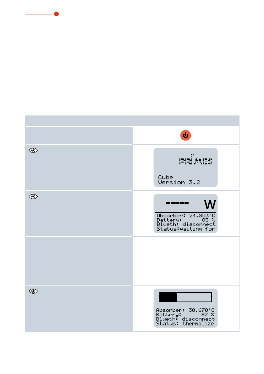
2. Press the on/off button.
The start menu appears.
After approx. 5seconds, the device is
ready for operation.
3. Turn on the laser. For a high measurement accuracy, we recommend an energy input of 300J per measurement (see chapter 12.2.2 on page25).
Observe the information on series measurements according to chapter 12.3 on
page26.
The thermalization is displayed by means
of a progress bar (duration approx.
15seconds).
28
Revision 01/2019 EN

35,0(6
Cube L1
4. To access the following windows, press
the on/off button for approx. 2seconds.
The window displays the following mea-
surement values:
• Laser power in W
• Absorber temperature in °C
• Corrected burst duration in ms (Time)
1)
With a cw laser, the max. power of the laser is
displayed in W (Pk Pow).
With a pulsed laser, the average power of a
pulse is displayed in W (Av Pow).
For a pulsed laser the measured values
of the pulse parameters are displayed:
• Total pulse duration in ms (Ontime)
• Total pulse pause in ms (Offtime)
• Uncorrected burst duration in ms
(uBurst)
• Number of pulses (Pulses)
• Max. Power of a pulse in W (Pk Pow)
• Average power in W (Av Pow)
• Energy in J
Further information on measuring with pulsed
lasers can be found in chapter 12.4 on
page27.
1)
The device turns off automatically after approx. 10minutes. You can also turn off the
device manually by keeping the on/off button pressed for approx. 5seconds.
Revision 01/2019 EN
29

35,0(6
Cube L1
13.2 Measuring results display
The last 14measuring values can be read off from the display of The Cube L1. You can
read off the last 30measuring values with the optional Android™ PRIMES Cube App for
mobile devices or optional LaserDiagnosticsSoftware LDS.
1. Press the on/off button for approx.
2seconds.
The measured values and the time
displayed.
2. Press the on/off button again for 2se-
conds to have the remaining measuring
values (no.8-14) displayed.
1)
With a cw laser, the maximum power of the
laser is displayed in W (Power) and the pulse
duration in ms (Time).
With a pulsed laser, the average power of a
pulse is displayed in W (Power) and the corrected burst duration in ms (Time).
1)
are
30
Revision 01/2019 EN

35,0(6
Cube L1
14 Measuring with the optional LaserDiagnosticsSoftware LDS
This chapter aims to provide some basic information as you get to know the Cube L1,
discussing the example of a measurement with the LaserDiagnosticsSoftware LDS. For a
detailed description of the software installation, file management and evaluation of the mea
sured data, please refer to the separate operating manual LaserDiagnosticsSoftware LDS.
Please read chapter12, „Important information for measuring with the Cube L1“, on
page23 first.
14.1 Connect the Cube L1 with the LaserDiagnosticsSoftware LDS
1. Connect the USB cable to the Micro-USB socket on the device and with the PC (see
Fig. 9.1 on page19) or activate the Bluetooth function on the PC. When the Bluetooth
connection is activated, the USB interface is deactivated.
2. Press the on/off button on the
device.
3. Start the LaserDiagnosticsSoft-
ware LDS.
4. Click on the Devices tab.
5. Click on the + Connect to de-
vice button under the tab.
-
The Connections window ap-
pears.
6. Click on the desired device.
7. Click on the Connect to device
button.
Revision 01/2019 EN
31

35,0(6
Cube L1
14.2 Select measurement mode CW Operation or Pulse Operation
The Cube L1 is established as a
connected device.
1. Click on the connected device.
2. Click on the CW Operation/Pul-
se Operation button
or on the drop-down list
CW Operation/Pulse Operation.
The corresponding Device
control opens.
The following toolbenches are
opened:
• CW Measurement/Pulse
Measurement to display the
measurement results.
• Cube series for displaying and
evaluating an entire CW measurement series.
Drop-down list
If the toolbenches have previously
been closed, click the Open measu-
rement toolbench button to open it
again.
32
Revision 01/2019 EN

35,0(6
Cube L1
14.3 Make settings for power saving functions and automatic measurement readiness
In the LaserDiagnosticsSoftware LDS
you can make additional settings for
power saving functions and the automatic measurement readiness.
1. Enter the desired settings in the
Device control.
2. Click on the Save settings
button.
Autom. ready for measurement By default, the device automatically returns to
measurement readiness after each measurement. If
you uncheck the box, you will need to reset the unit
after each measurement by briefly pressing the on/of
button.
Power Saving Function Continuous background on/off
Turn off lighting after (ins). The set time only applies if
the permanent backlight is switched off.
Switch the safety interlock on/off. For safety reasons
switching off the safety interlock is not recommended.
Switch off the device after an entered time
Revision 01/2019 EN
33

35,0(6
Cube L1
14.4 Start measurement
Measurements with the Cube L1 should be performed exclusively with a static (unmoving) laser beam.
The measurement in the Cube L1
starts when the laser is switched on.
The display field Start is therefore not
active.
If you have previously displayed a
measurement in the workbench,
press the New measurement button.
If the setting Autom. ready for
measurement (see chapter 14.3
on page33) is deactivated, briefly
press the on/off button on the device.
1. Observe the safety instructions
in chapter 12.1 on page23.
2. Turn on the laser.
The progress of the mea-
surement is indicated in the
Measurement is running and
then Measurement is finished
displays.
3. To stop recording a measurement, press the Stop button.
4. Turn off the laser.
34
Revision 01/2019 EN
35,0(6
Cube L1
14.5 Measuring results display
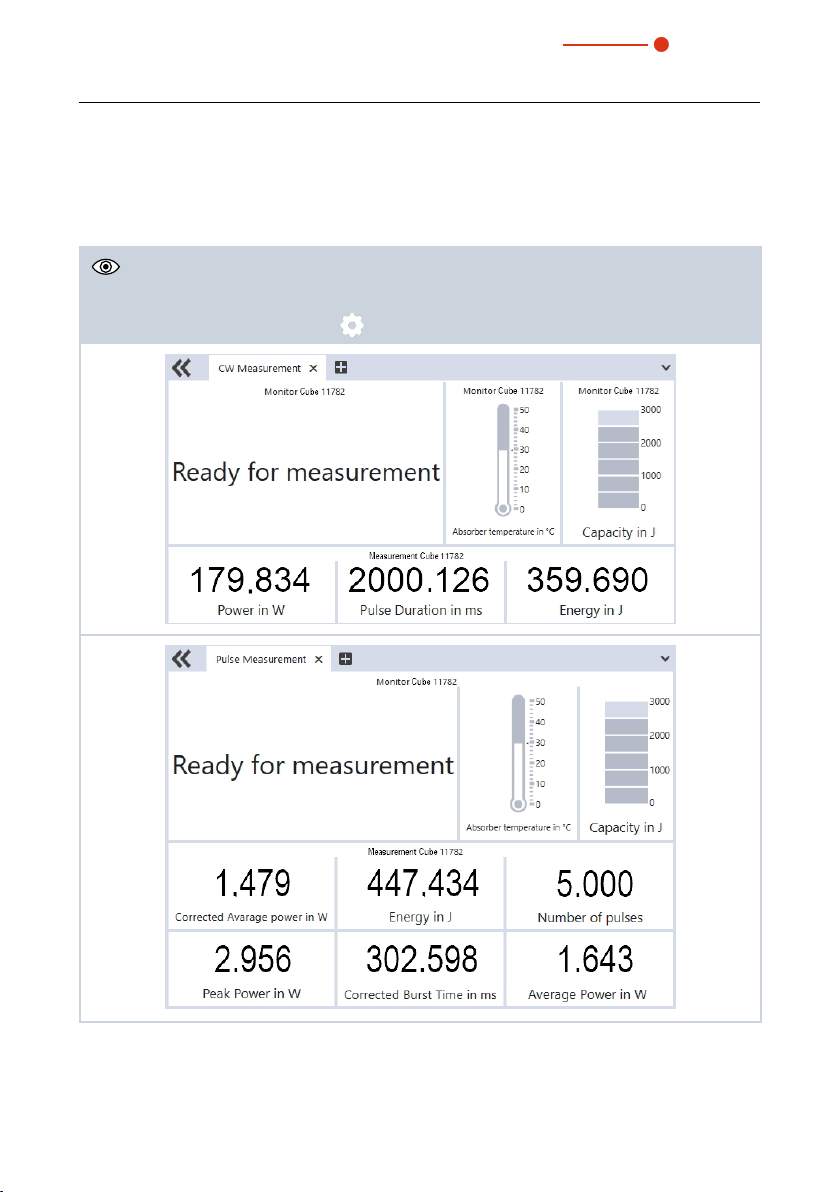
14.5.1 Displays in the toolbench CW Measurement or Pulse Measurement
The measuring results are displayed in the opened toolbenchs once the measurement has
been completed (see below).
By clicking on the gear symbol
you can adjust the displayed parameters.
Revision 01/2019 EN
35

35,0(6
Cube L1
14.5.2 Displays in the toolbench Cube series
Press the Load measurements button in the device control. The last 30 measurements
are readout from the Cube L1 and the measuring values are displayed in the left table.
Click on the arrow in the column Use to transfer the measuring values to the analysis
table. If required, you can assign target values to the measuring values in the analysis
table. By clicking on the gear symbol
Analysis tableMeasuring values
you can save and load these.
The two graphs below the table show the measurements marked in the analysis table
with a check.
By clicking on the gear symbol you can adjust the displayed parameters in both
graphs.
The left graph is the standard graph with the Cube L1 adapted parameter selection:
Index (number of measurement) and power in W.
In the right graph, select both parameters shown on the axes from the parameter list.
Press the CTRL key and highlight the first parameter for the x-axis (gray background)
and then the second parameter for the y-axis.
36
Revision 01/2019 EN

35,0(6
Cube L1
14.6 Load and delete measuring values
The Cube L1 stores the measured
values in an internal memory. The
measuring values can be displayed
and deleted in the LaserDiagnosticsSoftware LDS.
1. Click on the Load measure-
ments button.
• In the toolbench CW Measure-
ment/Pulse Measurement the
last measured measurement is
displayed.
• In the toolbench Cube series
the last 30 measurements are
loaded.
2. To delete all measured values, click on the Clear history
button.
• The measuring values in the
Cube L1 are deleted.
Revision 01/2019 EN
37

35,0(6
Cube L1
15 Measuring with the optional Cube App
With the Cube App for mobile devices with Android™ you can operate and evaluate the
device via a smartphone/tablet.
The Cube App is available for free in Google Play-Store/Apps. You need therefor a valid
Google Account. In the Google Play Store search box, type “Primes cube app”.
A bluetooth connection with the device makes it possible to read out and graphically
display the measured values (laser power, pulse length, and energy per pulse) with the
mobile end device. The Cube App also shows an overview of the device status (temperature, capacity, status notifications).
In the Cupe App you can make additional settings for power saving functions and the
automatic measurement readiness (see Tab. 15.1 on page38).
Function Possible settings
Autom. ready for measurement
Power Saving Function Continuous background on/off
Tab. 15.1: Functions and settings
By default, the device automatically returns to measurement readiness after each measurement. If you uncheck the box, you will need
to reset the unit after each measurement by briefly pressing the on/
of button.
Turn off backlight after (ins). The set time only applies if the permanent backlight is switched off.
Switch the safety interlock on/off. For safety reasons switching off the
safety interlock is not recommended.
Switch off the device after an entered time
Please find detailed information on the operation of the Cube App in the separate operating instructions Cube App. These can be found on the PRIMES website at: https://
www.primes.de/en/support/downloads/operating-manuals.html.
38
Revision 01/2019 EN

35,0(6
Cube L1
16 Maintenance and service
The operator is responsible for determining the maintenance intervals for the measuring
device.
PRIMES recommends a maintenance interval of 12months for inspection and validation
or calibration.
If the device is used only sporadically, the maintenance interval can also be extended up
to 24months.
16.1 Exchanging the protective window on the device
The protective window in the beam entrance is a wearing part and can be replaced
if necessary. Low levels of contamination of the protective window can be carefully
removed when cooled with Isopropanol (observe the manufacturer‘s safety instructions).
In case of heavy, non-removable contamination or damage, the protective window must
be replaced with a new one.
The protective window is coated with an antireflex coating and has low reflection values of less than 1%. To avoid increased reflection values, use only
original PRIMES protective windows.
Protective window diameter 55mm
Glass thickness 1.5mm
Order number 410-070-021 (1Stück); 410-011-018 (10Stück)
16.1.1 Safety instructions
DANGER
Severe eye or skin injury due to laser radiation
If the protective window is not correctly positioned, reflections can cause
directional laser radiation.
X
Ensure that the new protective window is positioned evenly in the indentation on the O-ring.
Revision 01/2019 EN
39

35,0(6
CAUTION
Burns due to hot components
After a measurement the optics below the protective window is hot!
Unintentional contact during the protective window exchange could lead
to burns.
X
Do not replace the protective window directly after a measurement.
X
Let the device cool down for an adequate period of time. The cooling
time varies depending on the laser power and the irradiation time.
NOTICE
Damaging/Destruction of the device
Contamination and fingerprints on the protective window can lead to
damage or shattering or splintering of the protective window during measuring operation.
X
Only replace the protective window in a dust-free environment.
X
Do not touch the protective window.
X
When exchanging the protective window wear powder-free latex gloves.
Cube L1
NOTICE
Damage to the optics
Pollution on the optics surface causes measurement deviation during laser beam irradiation by means of absorption and can damage the optics.
X
Ensure during exchanging the protective window that the subjacent optics will not be polluted.
40
Revision 01/2019 EN

35,0(6
Cube L1
16.1.2 Exchanging the protective window
1. Observe the safety instructions in chapter16.1.1, „Safety instructions“, on
page39.
2. Unscrew the 3Torx screws M3 x 6mm on the protective window holder.
3. Place the device as shown in Fig. 16.1 on page41 and carefully remove the
protective window holder upwards.
• Make sure that the inserted O-ring does not fall out of the device.
4. Remove old protective window from the device and dispose of it.
5. Wear powder-free latex gloves and insert the new protective window into the
device.
• Ensure that the inserted O-ring is not out of place.
6. Place the protective window holder according to Fig. 16.1 on page41.
7. Tighten the protective window holder with 3Torx screws M3 x 6mm.
8. Check for secure fit of the protective window holder:
• The protective window holder must lie flat against the device.
Torx screws
M3 x 6mm
O-ring
Fig. 16.1: Exchanging the protective window on the Cube L1
Revision 01/2019 EN
Protective win-
dow holder
Protective
window
Optics
41

35,0(6
Cube L1
17 Measures for the product disposal
Due to the Electrical and Electronic Equipment Act (“Elektro-G“) PRIMES is obliged to
dispose PRIMES measuring devices manufactured after August, 2005, free of charge.
PRIMES is a registered manufacturer in the German “Used Appliances Register“
(Elektro-Altgeräte-Register “EAR“) with the number WEEE-reg.-no. DE65549202.
Provided that you are located in the EU, you are welcome to send your PRIMES devices
to the following address, where they will be disposed free of charge (this service does
not include shipping costs):
PRIMES GmbH
Max-Planck-Str. 2
64319Pfungstadt
Germany
42
Revision 01/2019 EN

35,0(6
Cube L1
18 Declaration of conformity
Revision 01/2019 EN
43

35,0(6
19 Technical data
Measurement parameters
Power range 200 – 16000W
Wavelength range 1030 – 1090nm
Beam diameter on the protective window 1–7mm
Max. power density on the protective window 250kW/cm²
Irradiation time 0,1 – 2,0s
1)
Cube L1
1)
(depending on laser power)
Min. on/off times (duty cycle)
for pulsed lasers
Max. laser rise time 100µs
Energy per measurement 200 – 5000J
Recommended energy per measurement 500 – 2000J
Total duration until measurement value output <15s
Nominal measurement frequency 700J: 1cycle/min
Device parameters
Max. absorber temperature 120°C
Max. angle of incidence perpendicular to inlet
aperture
Max. centered tolerance ±2.0mm
Accuracy at an angle of incidence up to5° ±3%
Reproducibility ±1%
1)
The stated limit values are to be understood in correlation with the permitted maximum energy
(E = P ∙ t).
50 µs
(e.g. max. 10kHz at 50% duty cycle)
5000J: 1cycle/15min
±5°
44
Revision 01/2019 EN

35,0(6
Cube L1
Supply Data
Power supply Integrated lithium-ion battery, which can be
charged via a micro-USB port
Temperature range for charging the lithiumIon battery
Communication
Interfaces USB/Bluetooth
Dimensions and Weight
Dimensions (L x W x H) 92x97x110mm
Weight (approx.) 1700g
Environmental Conditions
Operating temperature range 15 – 40°C
Storage temperature range 5 – 50°C
Reference temperature 22°C
Permissible relative humidity
(non-condensing)
0 – 45°C
10 – 80%
Revision 01/2019 EN
45

35,0(6
20 Dimensions
Cube L1
110
92
Ø 50
35,5
33,5
21 50 21
97
X
M6 x 10
48,5
46
View X
55
All dimensions in mm (general tolerance ISO 2768-v)
46
M4 x 6
Revision 01/2019 EN

35,0(6
Cube L1
21 Appendix
21.1 System control (option)
An optional connection to the system control is available. Please contact your PRIMES
sales partner with any questions.
An overview of the PRIMES sales contacts can be found under
www.primes.de/en/contact.html or www.primes.de/en/worldwide.html.
Revision 01/2019 EN
47

PRIMES GmbH
Max-Planck-Str. 2
64319 Pfungstadt
Germany
Tel +49 6157 9878-0
info@primes.de
www.primes.de
 Loading...