

Primes CompactPowerMonitor Series, CPM C-9, CPM F-10, CPM F-20, CPM F-30 Operating Manual
...
Operating Manual
35,0(6
Translation of the original instructions
CompactPowerMonitor CPM
CPM C-9, CPM F-1, CPM F-10, CPM F-20, CPM F-30
LaserDiagnosticsSoftware LDS
PowerMonitorSoftware PMS
Revision 02/2019 EN


CompactPowerMonitor CPM
35,0(6
IMPORTANT!
READ CAREFULLY BEFORE USE.
KEEP FOR FUTURE USE.
Revision 02/2019 EN
3

CompactPowerMonitor CPM
35,0(6
Table of contents
1 Basic safety instructions 7
2 Symbol explanations 9
3 About this operating manual 10
4 Conditions at the installation site 10
5 Introduction 10
5.1 System description .................................................................................................................10
5.2 Measuring principle .................................................................................................................10
5.3 Overview of the CompactPowerMonitor CPM types ................................................................ 11
5.4 Connection overview ............................................................................................................... 12
5.5 Short overview installation .......................................................................................................13
6 Transport 14
7 Installation 15
7.1 Preparation .............................................................................................................................15
7.2 Installation position .................................................................................................................. 15
7.3 Align the CompactPowerMonitor CPM .................................................................................... 15
7.4 Install the CompactPowerMonitor CPM ................................................................................... 16
7.5 Remove the CompactPowerMonitor CPM ............................................................................... 19
8 Connect cooling circuit 20
8.1 Water quality ...........................................................................................................................20
8.2 Water pressure ........................................................................................................................ 20
8.3 Humidity .................................................................................................................................. 21
8.4 Temperature fluctuations of the inflowing cooling water ...........................................................22
8.5 Flow rate ................................................................................................................................. 22
8.6 Connect hoses ........................................................................................................................ 23
9 Electrical connection 24
9.1 Power supply ..........................................................................................................................24
9.2 PRIMES bus ............................................................................................................................ 24
9.3 Connect the safety interlock .................................................................................................... 25
9.4 Connecting the PC via the USB interface ................................................................................26
9.4.1 Scope of delivery ........................................................................................................26
9.4.2 Connect PC ................................................................................................................ 26
9.4.3 Install the USB driver manually ....................................................................................27
9.5 Connecting the PC via RS232 interface and optional PRIMES converter .................................28
9.5.1 Scope of delivery ........................................................................................................28
9.5.2 Connect PC ................................................................................................................ 28
9.6 Parallel operation of the CompactPowerMonitor PMC and, for example, the
FocusMonitor FM+ .................................................................................................................. 30
9.7 Analog output .........................................................................................................................31
10 Display, control elements and audible signals 32
10.1 Measured value display ...........................................................................................................32
10.2 Status display .........................................................................................................................32
10.3 External display (Option) .......................................................................................................... 33
10.4 Control Elements .....................................................................................................................33
10.5 Audible signals ........................................................................................................................33
4
Revision 02/2019 EN

CompactPowerMonitor CPM
35,0(6
11 Measuring with the optional LaserDiagnosticsSoftware LDS 34
11.1 Safety instructions ................................................................................................................... 34
11.2 Getting ready for operation ......................................................................................................35
11.3 Perform power measurement ..................................................................................................35
11.3.1 Connect the CompactPowerMonitor CPM with the LaserDiagnosticsSoftwareLDS .... 35
11.3.2 Choose power measurement mode ............................................................................ 36
11.3.3 Configure settings (Device control) ............................................................................36
11.3.4 Starting a power measurement ................................................................................... 37
11.3.5 Measurement results display ....................................................................................... 37
12 Install the PowerMonitorSoftware PMS 38
12.1 Start software and select operating mode ...............................................................................38
12.1.1 For connection via the RS232 and PRIMES converter ................................................. 38
12.1.2 For connection via the USB interface .......................................................................... 38
12.2 Testing the Interface ................................................................................................................39
12.3 Testing the communication of multiple devices ........................................................................40
13 Measuring with the PowerMonitor Software PMS 41
13.1 Safety instructions ................................................................................................................... 41
13.2 Getting ready for operation ......................................................................................................42
13.3 Starting the software ...............................................................................................................42
13.4 Perform power measurement ..................................................................................................42
13.5 The graphical user interface of the PowerMonitor Software PMS .............................................43
13.6 Measuring value display ..........................................................................................................44
13.6.1 Window A (Numerical display) ..................................................................................... 44
13.6.2 Window B (Graphical display) ...................................................................................... 45
13.6.3 Status window ............................................................................................................ 45
14 Storage 46
15 Maintenance and service 46
16 Measures for the product disposal 46
17 Declaration of conformity 47
18 Technical data 48
18.1 CPM C-9 ................................................................................................................................48
18.2 CPM F-1, CPM F-10, CPM F-20, CPM F-30 ........................................................................... 49
19 Dimensions 50
19.1 Dimensions CPM C-9..............................................................................................................50
19.2 Dimensions CPM F-1 ..............................................................................................................51
19.3 Dimensions CPM F-10 ............................................................................................................52
19.4 Dimensions CPM F-20 ............................................................................................................53
19.5 Dimensions CPM F-30 ............................................................................................................54
20 Appendix 55
20.1 Operation of the CompactPowerMonitor with PanelDisplay (without PC) .................................55
20.1.1 Pin assignment 9-pole D-Sub socket .......................................................................... 56
20.1.2 Measurement display .................................................................................................. 56
20.2 Mounting position of a CompactPowerMonitor CPM with oval wheel meter ............................57
20.3 Accessories fiber adapter ........................................................................................................ 58
Revision 02/2019 EN
5

CompactPowerMonitor CPM
35,0(6
PRIMES - The Company
PRIMES manufactures measuring devices used to analyze laser beams. These devices are employed for
the diagnostics of high-power lasers ranging from CO
length range from infrared through to near UV is covered, offering a wide variety of measuring devices to
determine the following beam parameters:
• Laser power
• Beam dimensions and position of an unfocused beam
• Beam dimensions and position of a focused beam
• Beam quality factor M²
PRIMES is responsible for both the development, production, and calibration of the measuring devices. This
guarantees optimum quality, excellent service, and a short reaction time, providing the basis for us to meet all
of our customers’ requirements quickly and reliably.
lasers and solid-state lasers to diode lasers. A wave-
2
PRIMES GmbH
Max-Planck-Str. 2
64319 Pfungstadt
Germany
Tel +49 6157 9878-0
info@primes.de
www.primes.de
6
Revision 02/2019 EN

CompactPowerMonitor CPM
35,0(6
1 Basic safety instructions
Intended use
The CompactPowerMonitor CPM is exclusively intended for measurements which are carried out in or nearby the optical path of high power lasers. Please mind and adhere to the specifications and limit values given
in chapter 18 „Technical data“ on page 48. Other forms of usage are improper. The information contained
in this operating manual must be strictly observed to ensure proper use of the device.
Using the device for unspecified use is strictly prohibited by the manufacturer. By usage other than intended
the device can be damaged or destroyed. This poses an increased health hazard up to fatal injuries. When
operating the device, it must be ensured that there are no potential hazards to human health.
The device itself does not emit any laser radiation. During the measurement, however, the laser beam is
guided onto the device which causes reflected radiation (laser class 4). That is why the applying safety regulations are to be observed and necessary protective measures need to be taken.
In measuring mode, the laser control’s safety interlock must be connected with the device.
Observing applicable safety regulations
Please observe valid national and international safety regulations as stipulated in ISO/CEN/TR standards as
well as in the IEC-60825-1 regulation, in ANSI Z 136 “Laser Safety Standards” and ANSI Z 136.1 “Safe Use
of Lasers”, published by the American National Standards Institute, and additional publications, such as the
“Laser Safety Basics”, the “LIA Laser Safety Guide”, the “Guide for the Selection of Laser Eye Protection”
and the “Laser Safety Bulletin”, published by the Laser Institute of America, as well as the “Guide of Control
of Laser Hazards” by ACGIH.
Necessary safety measures
If people are present within the danger zone of visible or invisible laser radiation, for example near laser
systems that are only partly covered, open beam guidance systems, or laser processing areas, the following
safety measures must be implemented:
• Connect the laser control’s safety interlock to the device. Check that the safety interlock will switch off the
laser properly in case of error.
• Please wear safety goggles adapted to the power, power density, laser wave length and operating mode
of the laser beam source in use.
• Depending on the laser source, it may be necessary to wear suitable protective clothing or protective
gloves.
• Protect yourself from direct laser radiation, scattered radiation, and beams generated from laser radiation
(by using appropriate shielding walls, for example, or by weakening the radiation to a harmless level).
• Use beam guidance or beam absorber elements that do not emit any hazardous substances when they
come in to contact with laser radiation and that can withstand the beam sufficiently.
• Install safety switches and/or emergency safety mechanisms that enable immediate closure of the laser
shutter.
• Ensure that the device is mounted securely to prevent any movement of the device relative to the beam
axis and thus reduce the risk of scattered radiation. This in the only way to ensure optimum performance
during the measurement.
Employing qualified personnel
The device may only be operated by qualified personnel. The qualified personnel must have been instructed
in the installation and operation of the device and must have a basic understanding of working with highpower lasers, beam guiding systems and focusing units.
Conversions and modifications
The device must not be modified, neither constructionally nor safety-related, without our explicit permission.
The device must not be opened e.g. to carry out unauthorized repairs. Modifications of any kind will result in
the exclusion of our liability for resulting damages.
Revision 02/2019 EN
7

CompactPowerMonitor CPM
35,0(6
Liability disclaimer
The manufacturer and the distributor of the measuring devices do not claim liability for damages or injuries
of any kind resulting from an improper use or handling of the devices or the associated software. Neither the
manufacturer nor the distributor can be held liable by the buyer or the user for damages to people, material
or financial losses due to a direct or indirect use of the measuring devices.
8
Revision 02/2019 EN

CompactPowerMonitor CPM
35,0(6
2 Symbol explanations
The following symbols and signal words indicate possible residual risks:
DANGER
Means that death or serious physical injuries will occur if necessary safety precautions are not
taken.
WARNING
Means that death or serious physical injuries may occur if necessary safety precautions are not
taken.
CAUTION
Means that minor physical injury may occur if necessary safety precautions are not taken.
NOTICE
Means that property damage may occur if necessary safety precautions are not taken.
The following symbols indicating requirements and possible dangers are used on the device:
Warning against a danger zone.
Do not touch.
Read and observe the operating instructions and safety guidelines before startup!
Further symbols that are not safety-related:
Here you can find useful information and helpful tips.
Revision 02/2019 EN
With the CE designation, the manufacturer guarantees that its product meets the requirements of
the relevant EC guidelines.
Call for action
X
9

CompactPowerMonitor CPM
35,0(6
3 About this operating manual
This documentation describes the installation and operation of the CompactPowerMonitor CPM and performing measurements using the CompactPowerMonitor CPM, the optional LaserDiagnosticsSoftware LDS
or the PowerMonitorSoftware PMS.
For measurement operation with a PC, the LaserDiagnosticsSoftware LDS (option) or the PowerMonitorSoftware PMS must be installed on the PC. The PowerMonitorSoftware PMS is included in the scope of delivery.
For a detailed description of the software installation, file management and evaluation of the measured data,
please refer to the separate operating manual LaserDiagnosticsSoftware LDS.
4 Conditions at the installation site
• The device must not be operated in a condensing atmosphere.
• The ambient air must be free of organic gases.
• Protect the device from splashes of water and dust.
• Operate the device in closed rooms only.
5 Introduction
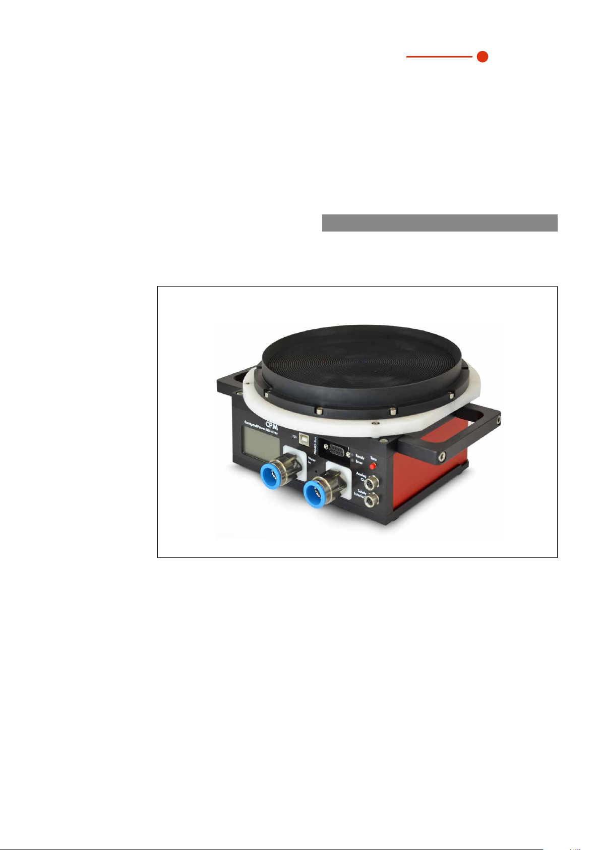
5.1 System description
The CompactPowerMonitor CPM is a measuring device for the determination of the laser power of laser
beams in the multikilowatt range. The main field of application is the control of laser powers of CO2 or solidstate lasers as well as high power diode lasers available at the work piece. The device is able to measure
both collimated and divergent beams.
5.2 Measuring principle
The CompactPowerMonitor CPM measures the laser power according to a calorimetric principle. The irradiated laser power is absorbed by a water-cooled absorber inside the device. By measuring the cooling water
flow rate and the respective temperature difference between the inflowing and the outflowing water, the
absorbed power is determined.
10
Revision 02/2019 EN

CompactPowerMonitor CPM
35,0(6
5.3 Overview of the CompactPowerMonitor CPM types
The various CompactPowerMonitor CPM types differ mainly in regards to the inlet aperture, the absorber
size, the measurable laser power, and the cooling water flow rate required by this. The port and operating
unit is the same on each device.
Device type Entrance aperture
CPM C-9
CPM F-1
CPM F-10
in mm
55
45 0.5
90 0.5
Average power density
in kW/cm²
5(Ø <10 mm)
5(Ø 10 – 30mm)
0,5(Ø 30 – 55 mm)
CPM F-20
CPM F-30
Tab. 5.1: Overview of the CompactPowerMonitor CPM types
135 0.5
180 0,5
Revision 02/2019 EN
11

35,0(6
5.4 Connection overview
CompactPowerMonitor CPM
Analog outputPRIMES bus (RS485)USB connection
Water inlet flow
(Water In)
Fig. 5.1: Connections of the CompactPower Monitor CPM
Water return flow
(Water out)
Safety interlock
12
Revision 02/2019 EN

CompactPowerMonitor CPM
35,0(6
5.5 Short overview installation
1. Installing the LaserDiagnosticsSoftware LDS on the PC (option)
• Please contact PRIMES or your PRIMES distribution partner to order the
software
2. Taking safety precautions Chapter 1 on page7
3. Installing the device
• Follow the safety instructions
• Set the installation position
• Mount the device stably
4. Connect the water-cooling
• Determine flow rate according Tab. 8.5 on page22
• Connect hoses (hose outer diameter of 12 mm)
5. Power supply
• Connect power supply
See separate Operating Manual
of the LaserDiagnosticsSoftware
LDS
Chapter 7 on page15
Chapter 8 on page20
Chapter 9.1 on page24
• Connect safety interlock
6. Connection with the PC
• Via USB (scope of delivery)
• Via RS232/RS485 converter (optional)
7. Parallel operation of CompactPowerMonitor PMC and,
• For example, the FocusMonitor
8. Perform the measurement
• Follow the safety instructions
• Perform the measurement with the optional LaserDiagnosticsSoftware LDS
9. Installing the PowerMonitorSoftware PMS on the PC
• Software is part of the scope of delivery
10. Perform the measurement
Chapter 9.3 on page25
Chapter 9.4 on page26
Chapter 9.5 on page28
Chapter 9.6 on page30
Chapter 11 on page34
Chapter 12 on page38
Chapter 13 on page41
• Follow the safety instructions
• Perform the measurement with the PowerMonitorSoftware PMS
Revision 02/2019 EN
13

35,0(6
6 Transport
NOTICE
Damaging/destroying the device
Hard hits or falls may damage the device.
Touching the absorber can lead to burn-in by the laser radiation at the points of contact.
Burn-in lead to damage to the absorber and increase the scattered radiation.
Do not touch the absorber.
X
Handle the device carefully when transporting it.
X
Only transport the device in the original PRIMES transport box.
X
NOTICE
Damage/destruction of the device caused by leaking or freezing cooling water
Leaking cooling water can damage the device. Transporting the device at temperatures near
or below freezing and without emptying the cooling circuit completely can damage the
device.
CompactPowerMonitor CPM
Empty the lines of the cooling circuit completely.
X
Even when the lines of the cooling circuit have been emptied, a small amount of residual
X
water will remain in the device at all times. This may leak out and end up inside the device.
Close the connector plug of the cooling circuit with the included sealing plug.
NOTICE
Damaging/Destruction of the flow rate meter
The flow rate meter is not designated for high rotational speed.
Do not use compressed air for emptying the cooling circuit.
X
14
Revision 02/2019 EN
CompactPowerMonitor CPM
35,0(6
7 Installation
7.1 Preparation
Check the space available before mounting the device, especially the required space for the connection
cables and hoses (please see chapter 19 „Dimensions“ on page 50). The device must be firmly assembled
and must be mounted with screws (see chapter 7.4 on page16).
7.2 Installation position
The CPM F-1 is to be operated in a horizontal position. With regard to the other device types, the installation
position can be chosen freely. Concerning the versions with a oval wheel meter, please mind the mounting
position according to chapter 20.2 on page57.
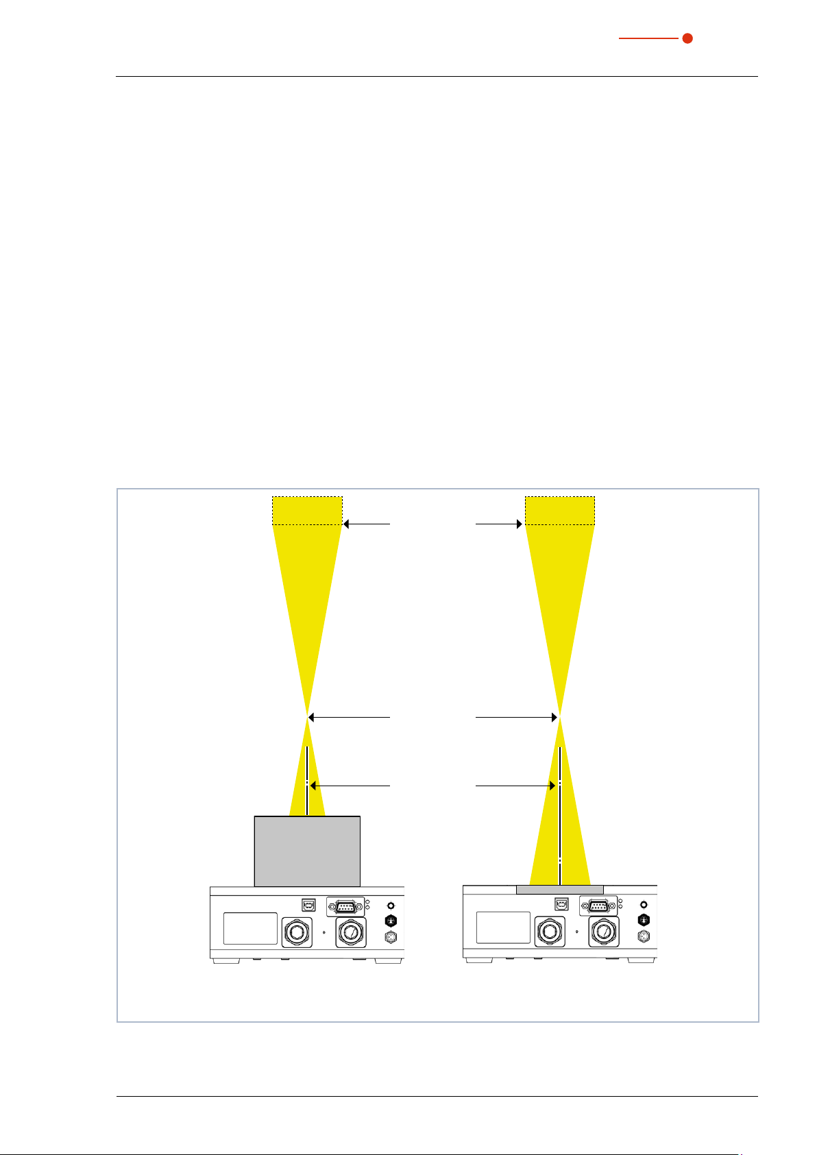
7.3 Align the CompactPowerMonitor CPM
The laser beam must hit the center of the entrance aperture not only with a collimated but also with a divergent beam. Please make sure that the beam diameter, the power, and the power density do not exceed the
limit values stated in the technical data.
For the correct alignment - especially with regard to divergent radiations behind the focusing optics - the
specifications in Fig. 7.1 on page15 are to be considered.
Aperture diameter on
CPM C-9 with conical
reflector 55mm
Focusing optics
Focusing plane
Beam axis
centerd in
inlet aperture
Aperture diameter for
devices with plane absorber
depending on device type:
45, 90, 135 oder 180mm
Fig. 7.1: Alignment of the CompactPowerMonitor CPM to the laser beam
Revision 02/2019 EN
CompactPowerMonitor CPM C-9
with conical reflector and
cylindrical absorber
CompactPowerMonitor
CPM F-1; F-10; F-20 and F-30
with plane absorber
15
CompactPowerMonitor CPM
35,0(6
7.4 Install the CompactPowerMonitor CPM
DANGER
Serious eye or skin injury due to laser radiation
If the device is moved from its calibrated position, increased scattered or directed reflection
of the laser beam occurs during measuring operation (laser class 4).
Mount the device so that it cannot be moved by an unintended push or a pull on the cables
X
or hoses.
NOTICE
Damage/Destruction of the device
Too long fixing screws can damage internal components in the device.
The fastening screws must not be screwed in more than 8 mm into the housing.
X
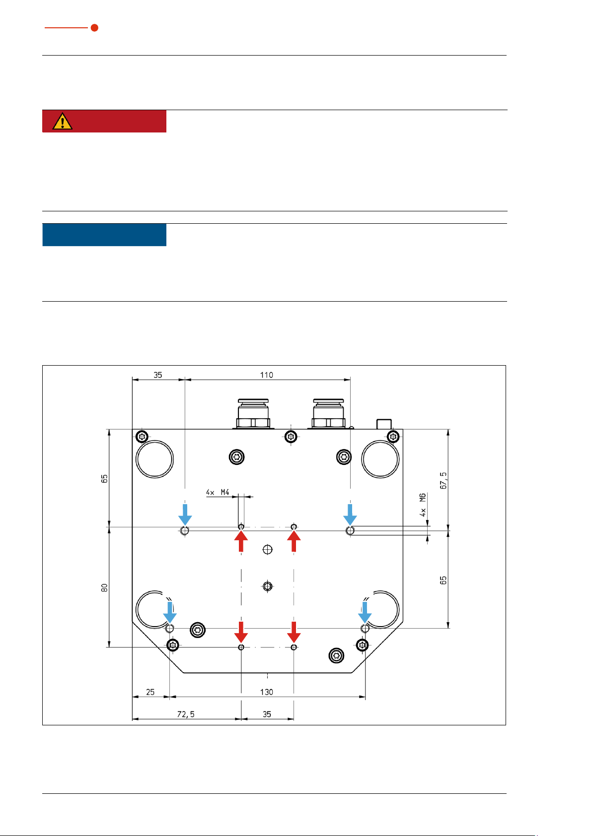
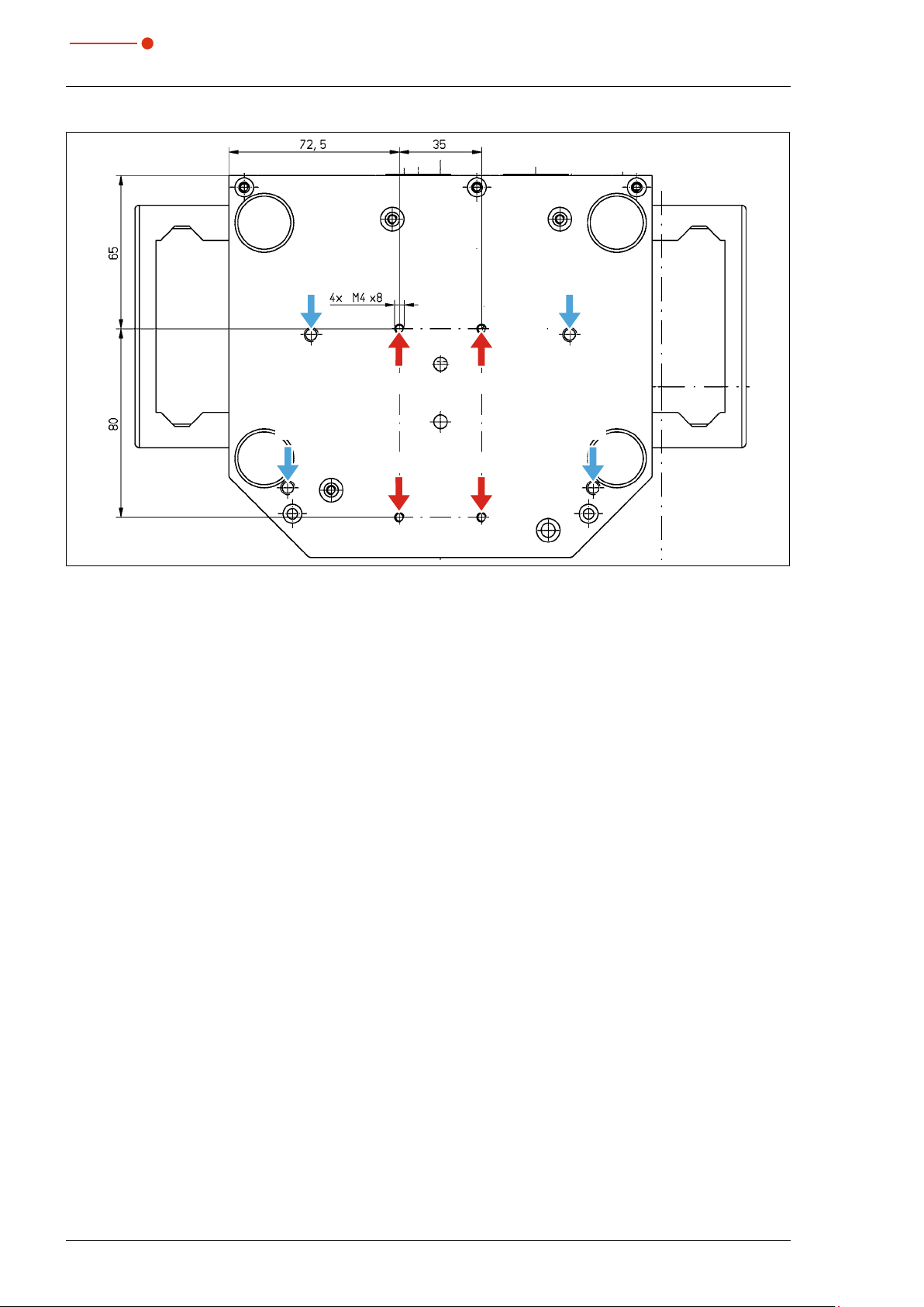
There are fastening screw threads M4 and M6 in the bottom of the housing which are intended for the
mounting on a customer‘s mount. We recommend screws of the strength class 8.8 and a tightening torque
of 5N∙m.
M6M6
M4
M6 M6
M4
Fig. 7.2: Fastening screw threads in the bottom of the housing of the CPM C-9
M4
M4
16
Revision 02/2019 EN
CompactPowerMonitor CPM
35,0(6
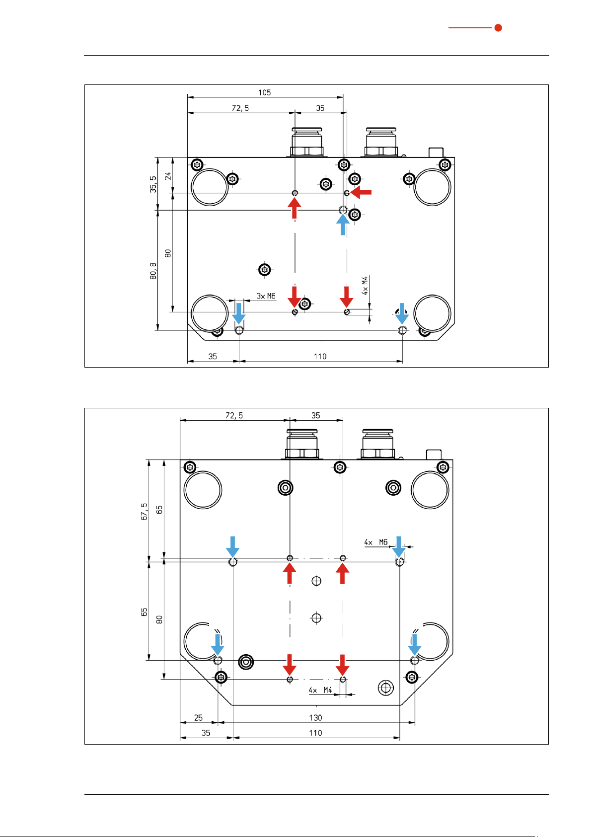
M4
M4
M6
M4M4
M6 M6
Fig. 7.3: Fastening screw threads in the bottom of the housing of the CPM F-1
M6
M6
M6
M4
M4
M4
M4
M6
Fig. 7.4: Fastening screw threads in the bottom of the housing of the F-10
Revision 02/2019 EN
17
CompactPowerMonitor CPM
35,0(6
M6
M4
M6
M4
Fig. 7.5: Fastening screw threads in the bottom of the housing of the CPM F-20
M4
M4
M6
M6
18
Revision 02/2019 EN

CompactPowerMonitor CPM
35,0(6
M6
M6
Fig. 7.6: Fastening screw threads in the bottom of the housing of the CPM F-30
M4 M4
M4 M4
M6
M6
7.5 Remove the CompactPowerMonitor CPM
1. First of all turn the the laser source off.
2. Turn off the voltage supply.
3. Ensure that moving parts, e.g. robot arms, etc. are at a standstill and that they cannot be set in motion
unintentionally.
4. Switch the cooling curcuit off.
5. Remove all connection cables and hoses of the cooling circuit.
6. Remove the device.
NOTICE
Damaging/Destruction of the flow rate meter
The flow rate meter is not designated for high rotational speed.
Do not use compressed air for emptying the cooling circuit.
X
7. Empty the cooling circuit completely and seal the connector plugs by means of the enclosed sealing
plugs.
Revision 02/2019 EN
19

35,0(6
8 Connect cooling circuit
DANGER
Fire hazard; Damage/Destruction of the device due to overheating
If there is no water cooling or a water flow rate which is insufficient, there is a danger of
overheating, which can damage the device or set it on fire.
Operate the device with a connected water cooling only and a sufficient water flow rate (see
X
chapter 8.5 on page22).
Connect the laser control’s safety interlock with the device. The safety interlock is only re-
X
leased if there is a minimum of cooling.
8.1 Water quality
NOTICE
Damage/Destruction of the device due to different chemical potentials
CompactPowerMonitor CPM
The parts of the device which get in contact with cooling water consist of copper, brass or
stainless steel. Connecting the unit to a colling curcuit containing aluminum components
may cause corrosion of the aluminum due to the different chemical potentials.
Do not connect the device on a cooling circuit in which aluminum components are installed.
X
• The device can be operated with tap water as well as demineralized water.
• Do not operate the device on a cooling circuit containing additives such as anti-freeze.
• Do not operate the device on a cooling circuit in which aluminum components are installed. Especially when
it comes to the operation with high powers and power densities, it may otherwise lead to corrosion in the
cooling circuit. In the long term, this reduces the efficiency of the cooling circuit.
• Should the cooling fail, the device can withstand the laser radiation for a few seconds. In this case, please
check the device as well as the water connections for damages.
• Large dirt particles or teflon tape may block internal cooling circuits. Therefore, please thoroughly rinse the
system before connecting it.
An operation with strongly deionized water (DI-water, conductivity < 30µS/cm) is only possible with
the respective connection parts – we would be glad to advise you as necessary.
8.2 Water pressure
Normally, 2 bar primary pressure according to Tab. 8.1 on page20 at the entrance of the absorber are
sufficient (in case of an unpressurized outflow).
Device type Primary pressure
CPM C-9, CPM F-1 2 bar
CPM F-10, CPM F-20, CPM F-30 3 bar
Tab. 8.1: Primary pressure
20
Revision 02/2019 EN
CompactPowerMonitor CPM
35,0(6
NOTICE
Damage/Destruction of the device due to overpressure
The maximum permissible water inlet pressure must not exceed 4bar.
X
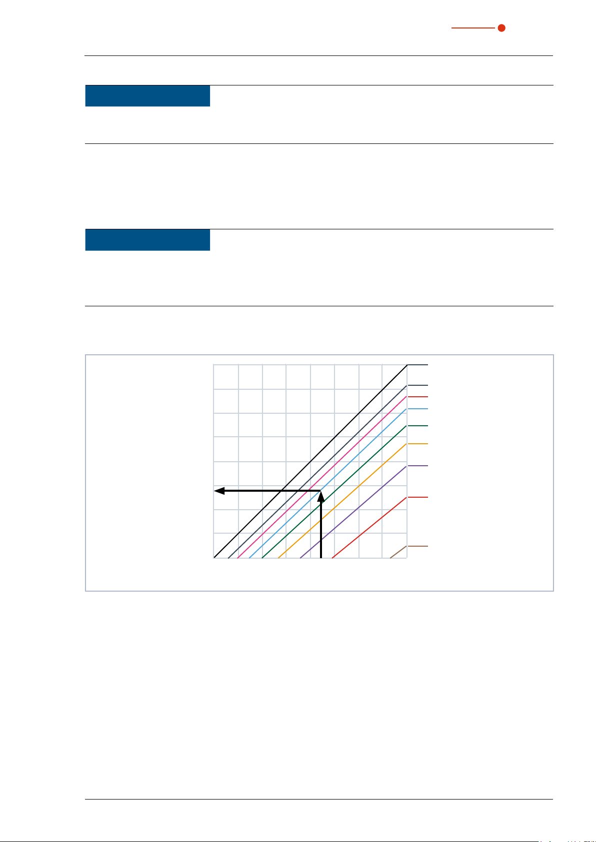
8.3 Humidity
• The device must not be operated in a condensing atmosphere. The humidity has to be considered in order
to prevent condensates within and outside the device.
• The temperature of the cooling water must not be lower than the dew point (see Tab. 8.2 on page21).
NOTICE
Damage/Destruction of the device due to condensing water
Condensation water inside of the device can lead to damage.
Mind the dew-point in Tab. 8.2 on page21.
X
Do only cool the device during the measuring operation. We recommend starting the cooling approx. 2minutes before the measurement and terminating it approx. 1 minute after the measurement.
40
35
30
25
20
15
10
Cooling water temperature in °C
5
0
Tab. 8.2: Dew point Diagram
Example
Air temperature: 22°C
Relative humidity: 60%
0 5 10 15 20 25 30 35 40
Air temperature in °C
100
80
70
60
50
40
30
20
Relative humidity in %
10
The cooling water temperature cannot fall below 14°C.
Revision 02/2019 EN
21

CompactPowerMonitor CPM
35,0(6
8.4 Temperature fluctuations of the inflowing cooling water
It is important that the temperature of the inflowing water remains constant. The fluctuation of temperature
should not exceed 0.5 ° C per minute or 0.05 ° C per 5 seconds.
8.5 Flow rate
The safety interlock is unblocked at:
Device type Flow rate in l/min
CPM F-1 0.5
CPM F-10, CPM C-9 4
CPM F-20 8
CPM F-30 15
Tab. 8.3: Minimum flow rate
The highest measurement accuracy is reached at a typical flow rate of:
Device type Flow rate in l/min
CPM F-1 1.5 – 2
CPM F-10, CPM C-9 8 – 11
CPM F-20 15 – 22
CPM F-30 25 – 35
Tab. 8.4: Recommended flow rate
For the maximum laser power in case of a fixed flow rate the following rule is applicable:
Flow rate multiplied by 1.4 = maximum laser power. For 5 l/min this equals about 7 kW.
This calculation serves to prevent a possible overload.
Typical flow rates and temperature rises for the highest measurement accuracy can be found in Tab. 8.5 on
page22.
Beam power in kW
8 7 6 5 4 3 2 1,5 1 0,5
12 9.55 8.36 7.17 5.97 4.78 3.58 2.39 1.79 1.19 0.60
11 10.42 9.12 7.82 6.51 5.21 3.91 2.61 1.95 1.30 0.65
10 11.46 10.03 8.60 7.17 5.73 4.30 2.87 2.15 1.43 0.72
9 12.74 11.15 9.55 7.96 6.37 4.78 3.18 2.39 1.59 0.80
8 14.33 12.54 10.75 8.96 7.17 5.37 3.58 2.69 1.79 0.90
7 16.38 14.33 12.28 10.24 8.19 6.14 4.09 3.07 2.05 1.02
Flow rate in l/min
6 19.11 16.72 14.33 11.94 9.55 7.17 4.78 3.58 2.39 1.19
5 22.93 20.06 17.20 14.33 11.46 8.60 5.73 4.30 2.87 1.43
Temperature rise in °C
Tab. 8.5: Flow rates/temperature rise/beam power - a linear extrapolation up to 20 kW is possible
22
Revision 02/2019 EN

CompactPowerMonitor CPM
35,0(6
8.6 Connect hoses
The flow direction (Water In/Water Out) indicated on the device has to be strictly observed. The plug connectors are intended for hoses with an outer diameter of 12 mm.
The plug connectors are sealed with sealing plugs in order to ensure that no residual water can escape.
Please remove the the sealing plugs and keep for future transportations or shipping.
Remove the sealing plugs of the water connections
Release ring
1. Push
2. Pull
Fig. 8.1: Remove the sealing plugs of the water connections
1. Please push down the release ring of the connection and pull
out the plug with your free hand.
2. Remove the sealing plugs of the water connections and keep
it in a save place.
3. Close the flow line (Water In) and the return flow (Water Out)
of the device, by inserting the hose as far as possible (approx.
20mm deep).
Revision 02/2019 EN
23

CompactPowerMonitor CPM
35,0(6
9 Electrical connection
9.1 Power supply
The CompactPowerMonitor CPM requires a supply voltage of 24V±5% (DC) for the operation. A suitable
power supply with an adapter is included in the scope of delivery.
Please use only the provided PRIMES power supply and connection lines.
When the CompactPowerMonitor CPM is connected via the USB interface, the power is supplied by the PC
through the USB interface. If other devices are connected to the PC that also consume power, it may be
necessary to use a separate power supply.
CPM
Adapter
Fig. 9.1: Connect power supply using the example of the CPM F-10
PRIMES power supply
Connect the power supply unit via the adapter to the 9pin D-Sub socket (RS485) of the CompactPowerMonitor CPM.
9.2 PRIMES bus
The device is supplied with power by means of the 9 pin D-Sub socket. Using an optional PRIMES converter
or a PRIMES power supply with integrated converter, the socket can also be used to connect a PC to enable
communication (see chapter 9.5 on page28).
D-Sub socket, 9 pin
(top view, plug-in side)
15
Pin Function
1 Ground
2 RS485 (+)
3 +24V
4 Not assigned
69
Tab. 9.1: Pin assignment PRIMES bus
24
5 Not assigned
6 Ground
7 RS485 (–)
8 +24V
9 Not assigned
Revision 02/2019 EN

CompactPowerMonitor CPM
35,0(6
9.3 Connect the safety interlock
The device can be damaged when the water flow rate is too low, the inlet temperature Tin too high, or the
temperature difference TD too great. The safety interlock protects the device from damages by turning off the
laser in this case.
If the water flow rate is too low, the inlet temperature Tin is too high, or the temperature difference TD is too
great, then Pin 1 and Pin 4 are connected. Pin 1 and Pin 3 are connected when required by the operating
condition values.
NOTICE
Damaging/Destruction of the device
If the safety interlock is not connected, this may lead to damages to the device due to overheating.
Make sure to connect the safety interlock of the laser control in a way that ensures that the
X
laser is turned off whenever this connection is interrupted.
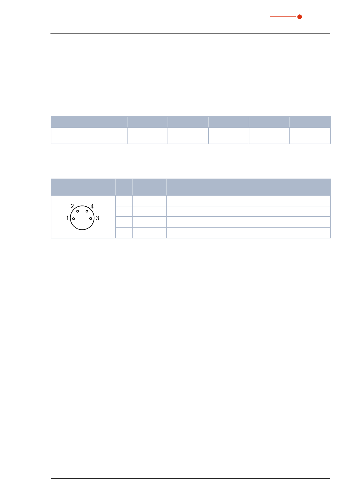
A suitable connection cable with a device plug and free ends is included in the scope of delivery
Pin assignment socket
(top view, plug-in side)
4 1 Brown Mutual pin
13
Tab. 9.2: Pin assignment safety interlock
Pin Wire color Function
3 Blue Connected with Pin1 when ready for operation
4 Black Connected with Pin1 when in safety interlock mode
(water flow rate too low)
Revision 02/2019 EN
25

35,0(6
9.4 Connecting the PC via the USB interface
9.4.1 Scope of delivery
For the communication with the PC via USB the following is required:
CompactPowerMonitor CPM
PRIMES standard power supply
with adapter
(included in scope of delivery)
+
Fig. 9.2: Scope of delivery
USB connecting cable
(included in scope of delivery)
In case of short lines (with a maximum
length of 3 m) and a high quality USB cable
(scope of delivery), the voltage supply from
the PC via USB can be sufficient.
9.4.2 Connect PC
If the PRIMES USB connecting cable and PRIMES power supply are connected simultaneously
during initial installation, the USB driver may not be recognized in exceptional cases. During initial
installation, only connect the device via the USB connecting cable. Once the USB connection has
been established, the power supply can be connected as necessary.
1. Connect the device to the PC via the PRIMES USB connection cable (plug/plug):
• For a PC with an Internet connection, the USB driver is automatically installed.
• For a PC without an Internet connection, the USB driver must be installed manually (see chapter 9.4.3 on
page27). The USB driver has to be installed before the device is connected.
2. If necessary, connect the power supply unit via the adapter to the 9pin D-Sub socket (RS485) of the
device.
CPM
Adapter
PRIMES connection cable,
plug/plug
L=3 m
USB
PC
Fig. 9.3: Connection of the PC via USB using the example of the CPM F-10
In general, a USB interface without additional interference suppression measures is not in conformity with the EMC directive. In industrial environments with strong sources of interference, there could
therefore be disruptions in the connection and disruptions in data transmission.
RIMES power supply
26
Revision 02/2019 EN
CompactPowerMonitor CPM
35,0(6
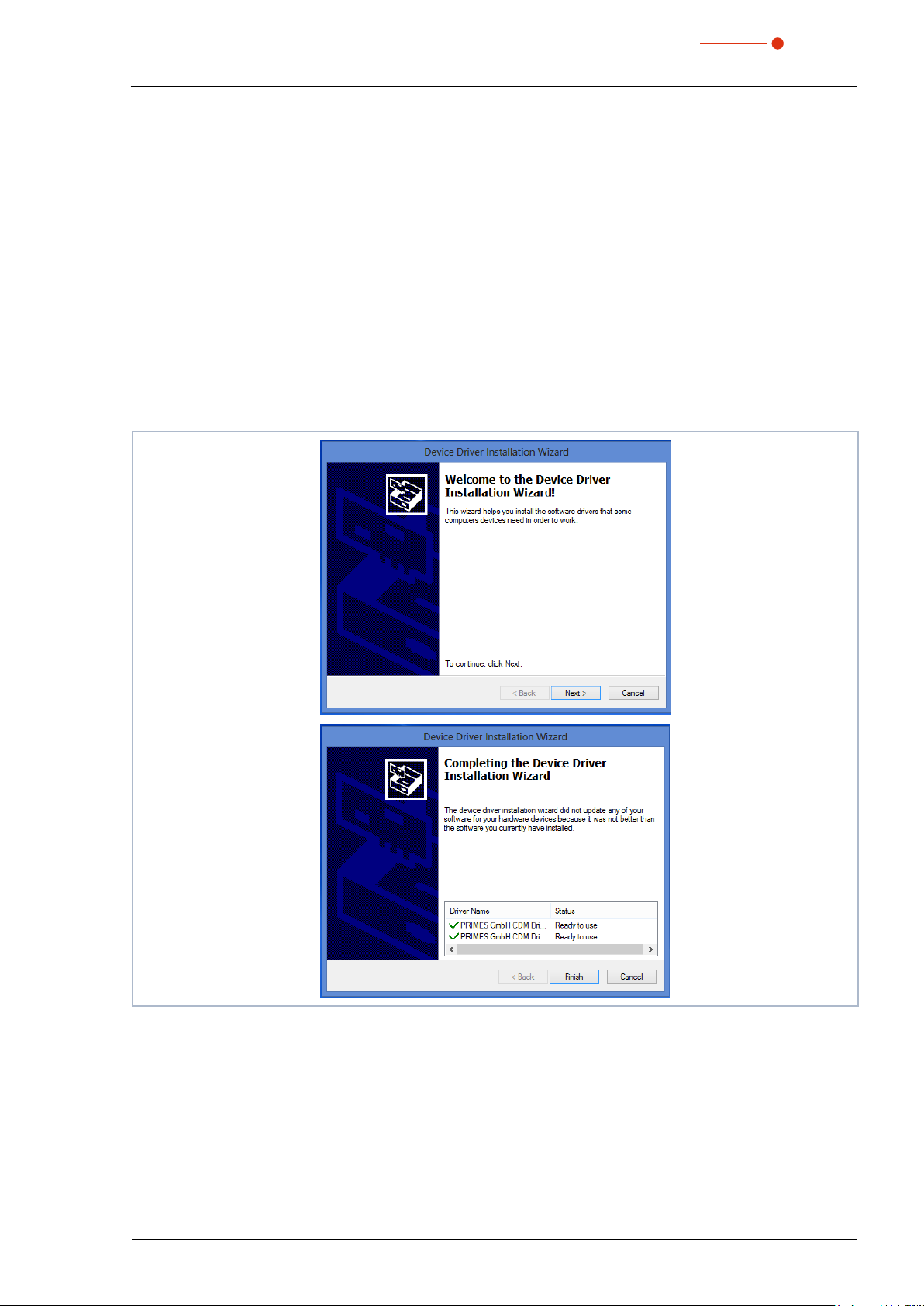
9.4.3 Install the USB driver manually
The PRIMES USB driver for all USB-capable devices can be found on the enclosed PRIMES data medium or
on the PRIMES website at: https://www.primes.de/en/support/downloads/software.html
®
The USB driver can be installed for 32bit and 64bit Windows
data medium included in the scope of delivery. Administrator rights are necessary in order to install the USB
driver.
• Driver installation software dpinst_x64.exe for Windows® 7/8/10 (64bit)
• Driver installation software dpinst_x86.exe for Windows® 7 (32bit)
1. Connect the supplied PRIMES data medium to your PC.
2. Open the USBdriver folder.
3. Start the desired USB driver installation software (32- or 64bit) by double-clicking.
4. Follow the instructions on the screen.
operating systems by means of the PRIMES
Fig. 9.4: Windows® menu for USB driver installation
5. Click Finish in order to complete the installation.
6. Connect the CompactPowerMonitor CPM according to chapter 9.4.2 on page26.
Revision 02/2019 EN
27

CompactPowerMonitor CPM
35,0(6
9.5 Connecting the PC via RS232 interface and optional PRIMES converter
When there is no free D-sub socket on the PC, the device can be connected to the PC with the optional
PRIMES USB converter and the PRIMES connecting cable (socket/socket).
9.5.1 Scope of delivery
For the communication with the PC via RS232 interface, you require:
PRIMES standard power
supply with adapter (in-
cluded in scope of delivery)
Fig. 9.5: Scope of delivery
9.5.2 Connect PC
NOTICE
Damaging/Destruction of the device
Connecting or disconnecting the bus cable when it is connected with the supply voltage
leads to voltage peaks, which may damage communication modules of the measuring device.
Only establish connections when the power supply unit is turned off. Do not disconnect any
X
plugs as soon as the supply voltage is switched on.
PRIMES RS485/RS232 converter
(option, Order-No. 180-005-003)
+
D-Sub connecting cable
(option, Order-No. 180-004-009)
+
USB-Serial converter
(option, Order-No. 180-006-001)
+
28
NOTICE
Damaging/Destruction of the PC
The supply voltage of 24V is ensured by means of the RS485-based PRIMES bus. If the
measuring device is directly connected with the PC, the PC may be damaged.
Only connect your PC with the measuring system via a PRIMES RS485/RS232 interface
X
converter.
Revision 02/2019 EN

CompactPowerMonitor CPM
35,0(6
1. Connect the device with the PRIMES converter via the PRIMES connector cable (plug/plug).
2. Connect the PC with the PRIMES converter via the PRIMES connector cable (socket/socket).
3. Connect the power supply unit via the adapter to the 9pin D-Sub socket (RS485) of the PRIMES converter.
CPM
PRIMES converter
PRIMES connection cable,
socket/socket
L=2 m
PRIMES connection cable
plug/plug
L=2 m
Adapter
or
RS232 USB
PC
PRIMES power supply
PRIMES-
USB-Serial converter
L=0.1m
Fig. 9.6: Connection to the PC via RS232 and PRIMES converter using the example of the CPM F-10
Revision 02/2019 EN
29

CompactPowerMonitor CPM
35,0(6
9.6 Parallel operation of the CompactPowerMonitor PMC and, for example, the FocusMonitor FM+
A measuring device, such as the FocusMonitor FM+, can be connected with the CompactPowerMonitor
CPM via the RS485 interfaces (PRIMES bus). The signal of the CompactPowerMonitor CPM is transmitted to
the PC through the ethernet interface of the FocusMonitor FM+.
PRIMES Power supply
Ethernet
PRIMES bus RS485
socket/socket
L
=10m
max
Fig. 9.7: Connection of the FocusMonitor FM + with the CompactPowerMonitor using the example of the CPM F-10
NOTICE
Damage/Destruction of the device due to overvoltage
When disconnecting the electric cables during operation (when the supply voltage is connected), voltage peaks can be generated that could destroy the communication modules of
the measuring devices.
Turn off the power supply before disconnecting the bus cables.
X
30
Revision 02/2019 EN
CompactPowerMonitor CPM
35,0(6
9.7 Analog output
The CompactPowerMonitor CPM has an analog voltage output (analog output) that emits a voltage value
analogous to the measured laser power. The analog signal is effected via the 4-pin device socket M8 (see
Fig. 5.1 on page12). The output voltage amounts to a maximum of 10 V. The output voltage of 10 V is
scaled to the maximum output value of the connected device (see Tab. 9.3 on page31). A suitable connection cable is included in the scope of delivery.
The load resistance at the analog output should not be smaller than 100 kOhm.
CPM C-9 CPM F-1 CPM F-10 CPM F-20 CPM F-30
An output voltage of 1V
equals approx.
Tab. 9.3: Output voltage and laser power
1 000W 250 W 1 000W 2 500W 4000W
When power is supplied through the USB port, it is not necessary to hook up 24 V through Pin 1 and Pin 2.
Pin assignment socket
(top view, plug-in side)
Tab. 9.4: Socket assignment of the analog output
Pin Wire color Function
1 Brown 24V (input power supply)
2 White Ground for the power supply
3 Blue Ground for the analog signal
4 Black Analog signal 0 – 10V (output)
Revision 02/2019 EN
31
CompactPowerMonitor CPM
35,0(6
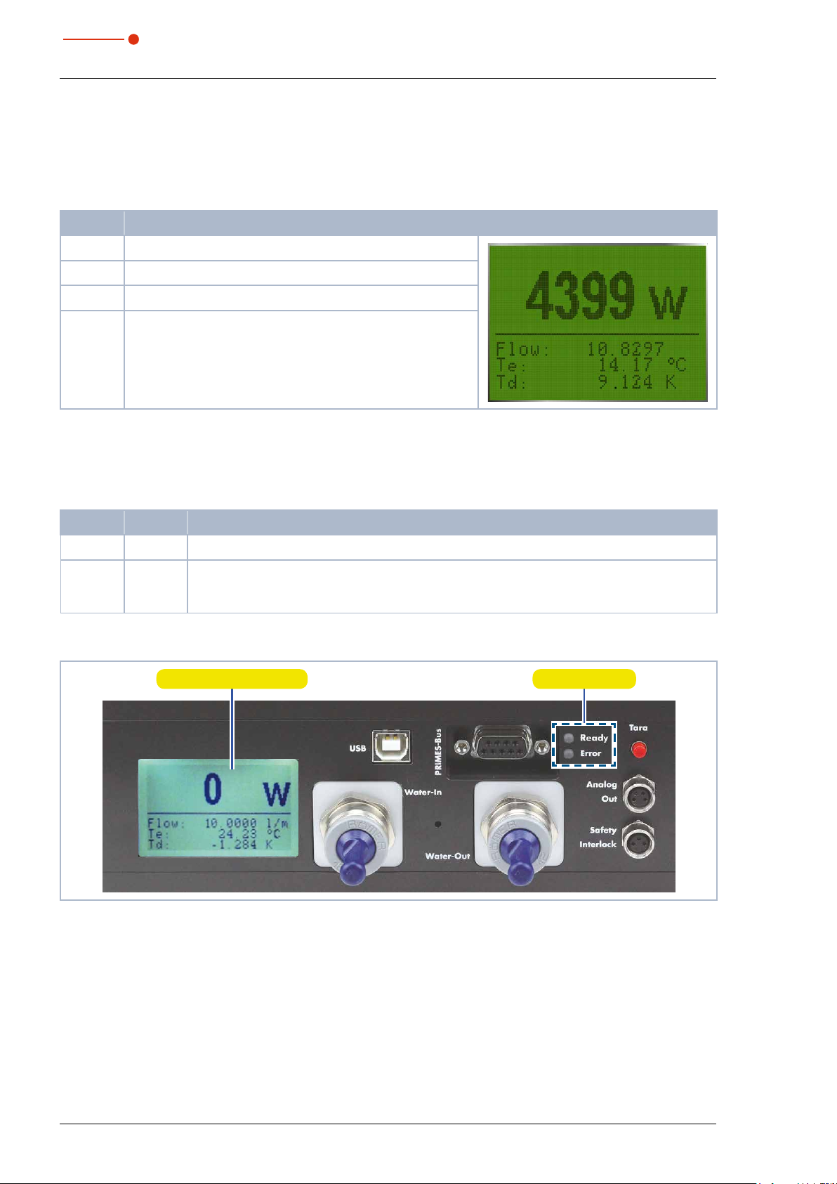
10 Display, control elements and audible signals
10.1 Measured value display
The display on the connector side of the device shows the following measurement values:
Display Meaning
W Laser power in W
Flow Water flow rate in l/min
Te Water temperature at the entrance in °C
Td Temperature difference between water input and output in
Tab. 10.1: Meaning of the measured display
Kelvin (a temperature difference of 1K corresponds to a temperature difference of 1°C).
10.2 Status display
The status displays indicate different states of the CompactPower Monitor CPM.
LED Color Meaning
Ready Green Voltage supply is turned on.
Error
Tab. 10.2: Meaning of the status display
Red
Possible errors: Safety interlock has triggered:
The water flow rate is too low, the inlet temperature T
ence T
is too great.
D
Measured value display Status display
is too high, or the temperature differ-
in
Fig. 10.1: Display
After the connection of all cables you can turn on the power supply. The green status display (Ready) on the
front of the CompactPowerMonitor CPM lights up. In case of an error, the red status display (Error) lights up.
32
Revision 02/2019 EN

CompactPowerMonitor CPM
35,0(6
10.3 External display (Option)
The external display (PanelDisplay, Order-No. 130-005-003) allows the measured power to be displayed
without PC at a maximum distance of approx. 20m from the measuring position (see chapter 20.1 on
page55).
10.4 Control Elements
By means of the Tara button, the measurement values can be reset to zero.
We recommend the following procedure before every measurement:
1. Turn on the cooling and wait for approx. 2 minutes.
2. Push the Tara button.
3. Start the measurement according to chapter 11 on page34 or chapter 13 on page41.
Tara button
Fig. 10.2: Tara button
10.5 Audible signals
When the temperature of the absorber exceeds 60°C, the warning signal will sound:
1. Turn off the laser immediately.
If water leaks out of the device after the warning signal has sounded, the device may be damaged by overheating and cease to be operable. The overpressure caused in the standing cooling water can also cause
leaks in the hoses and connectors.
2. Check the device for leaks.
• In the case a leak is identified, please send the device to PRIMES for inspection.
If no leaks are identified:
3. Check the absorber for possible damage.
4. Check the flow rate and proper flow rate in accordance with Chapter 8.5 on page22.
5. Perform a function test:
• Check that the safety interlock will turn off the laser properly in case of error.
• If the device stops working properly, please send the device to PRIMES for inspection.
Revision 02/2019 EN
33

CompactPowerMonitor CPM
35,0(6
11 Measuring with the optional LaserDiagnosticsSoftware LDS
11.1 Safety instructions
DANGER
Serious eye or skin injury due to laser radiation
During the measurement the laser beam is guided on the device, which causes scattered or
directed reflection of the laser beam (laser class 4).
For example, with 10kW of laser power, some 100 W of scattered radiation can occur.
The CompactPowerMonitor CPM must not be operated in any of the available configurations without taking the following precautions.
Please wear safety goggles adapted to the power, power density, laser wave length and
X
operating mode of the laser beam source in use.
Wear suitable protective clothing and protective gloves.
X
Protect yourself from laser radiation by separating protective devices (e.g. by using appro-
X
priate shielding).
DANGER
Serious eye or skin injury due to laser radiation
If the device is moved from its calibrated position, increased scattered or directed reflection
of the laser beam occurs during measuring operation (laser class 4).
When mounting the device, please ensure that it cannot be moved, neither due to an unin-
X
tended push or a pull on the cables or hoses.
DANGER
Fire hazard; Damage/Destruction of the device due to overheating
If the safety interlock is not connected, the unit may overheat and be damaged or catch fire
if there is no water or too low flow.
Connect the laser control’s safety interlock to the device. Check that the safety interlock will
X
switch off the laser properly in case of error.
WARNUNG
Burn hazard; Damage of the absorber – Do not touch
Touching the hot absorber can cause severe burns.
Touching the absorber can lead to burn-in by the laser radiation at the points of contact.
Burn-in lead to damage to the absorber and increase the scattered radiation.
Do not touch the absorber.
X
34
Revision 02/2019 EN
CompactPowerMonitor CPM
35,0(6
11.2 Getting ready for operation
1. Connect the laser control’s safety interlock to the device.
• Check that the safety interlock will switch off the laser properly in case of error.
2. Turn on the voltage supply.
• The green status display (Ready) must light up.
3. Please wait, until the measured value display is illuminated.
4. Turn on the water cooling.
• After a few seconds the red status display (Error) must extinguish.
5. After approx. 2 minutes, the device temperature equals the temperature of the cooling water.
• The CompactPowerMonitor CPM is now ready for operation.
11.3 Perform power measurement
For the purpose of getting to know the CompactPowerMonitor CPM, this chapter describes a power measurement with the LaserDiagnosticsSoftware LDS as an example.
For a detailed description of the software installation, file management and evaluation of the measured data,
please refer to the separate operating manual LaserDiagnosticsSoftware LDS.
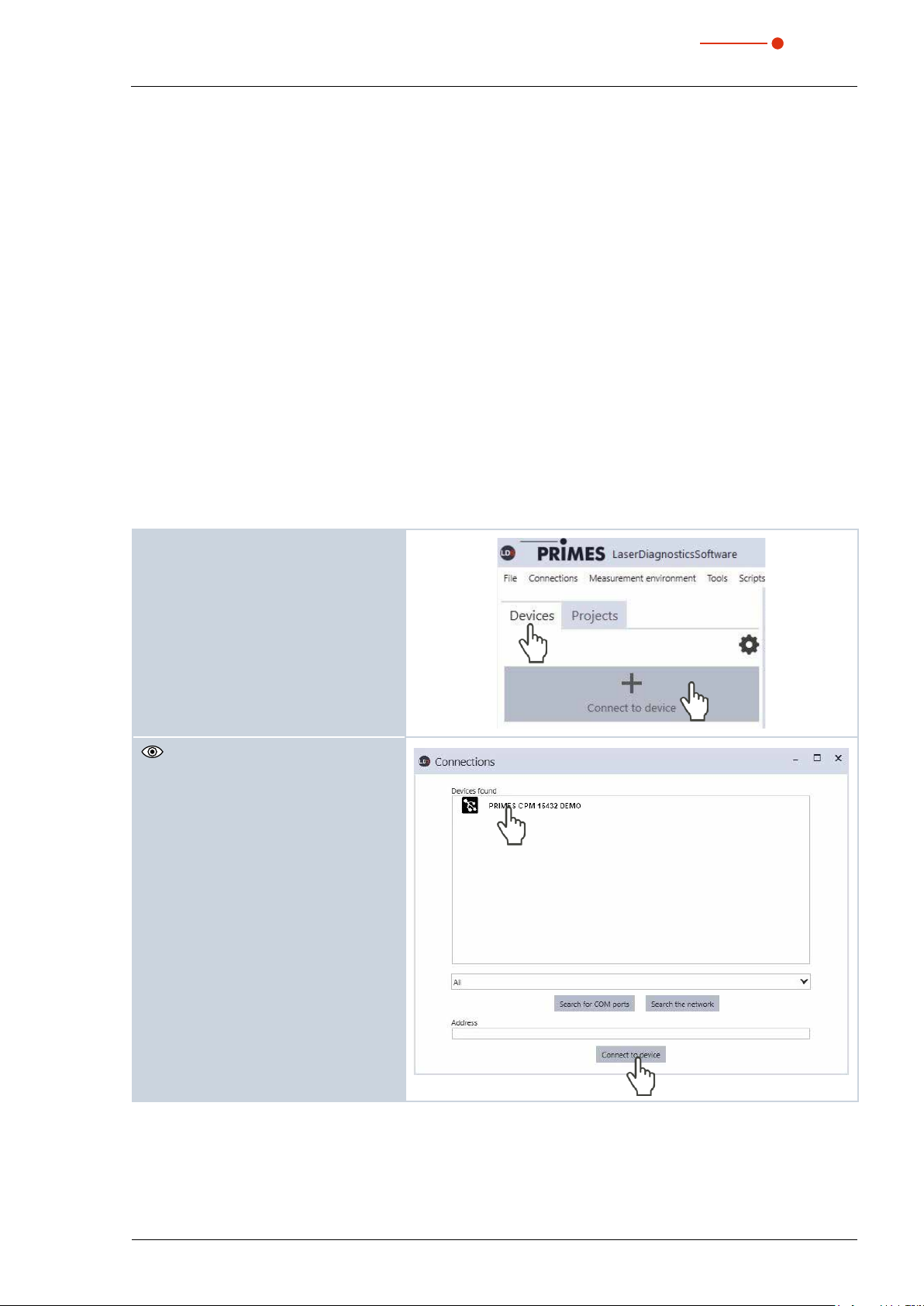
11.3.1 Connect the CompactPowerMonitor CPM with the LaserDiagnosticsSoftwareLDS
1. Start the LaserDiagnosticsSoftwareLDS.
2. Click on the Devices tab.
3. Click on the + Connect to device
button under the tab.
The Connections window appears.
4. Click on the desired device.
5. Click on the Connect to device button.
Revision 02/2019 EN
35

35,0(6
11.3.2 Choose power measurement mode
The CompactPowerMonitorCPM is
displayed as a connected device.
1. Click on the connected device.
The corresponding Device control
opens.
The Power Measurement toolbench
opens.
CompactPowerMonitor CPM
11.3.3 Configure settings (Device control)
1. Start and end a measurement as
described in chapter 11.3.4 on
page37.
Before the device offset can be determined, the device must go through a
thermalization period.
2. After a measurement has ended and
without the laser turned on, press the
Start button.
3. After the display in the Power Mea-
surement tool stabilizes, click on the
Stop button.
4. Click on the Set current value as
offset button.
• The value will show up in the Additional Offset in W entry window.
• The device offset can also be entered
manually with the tara key on the device (see chapter 10.4 on page33).
5. Enter the measurement duration in
min.
• If a measurement duration is not
entered, the power will be measured
indefinitely.
6. Enter the Measurement frequency
in Hz.
36
Revision 02/2019 EN

CompactPowerMonitor CPM
35,0(6
11.3.4 Starting a power measurement
1. Follow the safety instructions in chapter 11.1 on page34.
2. Turn on the laser.
3. Click on the Start button.
The progress of the measurement is
displayed.
When a measuring period is entered in the
Device control > Measurement duration in min. entry window, the measure-
ment is terminated automatically.
4. Click on the Stop button.
• The measurement is completed.
5. Turn off the laser.
11.3.5 Measurement results display
The measurement results are shown in the opened tool Power Measurement after the measurement is com-
pleted (see below).
A detailed description of the tools and the assessment of the measuring results can be found in the separate
operating manual for the LaserDiagnosticsSoftware LDS.
Revision 02/2019 EN
37

CompactPowerMonitor CPM
35,0(6
12 Install the PowerMonitorSoftware PMS
For the operation of the CompactPowerMonitor CPM with a PC, the PowerMonitorSoftware PMS has to be
installed. The installation is started by double-clicking the file “PMS v.2.xx Setup” and following the instructions on the screen.
12.1 Start software and select operating mode
Start the PowerMonitorSoftware PMS by double-clicking the PowerMonitorSoftware PMS-Icon .
12.1.1 For connection via the RS232 and PRIMES converter
See „Fig. 9.6: Connection to the PC via RS232 and PRIMES converter using the example of the CPM F-10“
on page29.
After the start-up the software tries to establish a connection with the serial interface “COM2”. If the serial interface “COM1” is the only one available, as it is the case with most notebooks, you have to select it explicitly
in Com port in the menu Communication > Free Communication.
When using the USB serial converter, please choose the operating mode USB2Serial.
12.1.2 For connection via the USB interface
See „Fig. 9.3: Connection of the PC via USB using the example of the CPM F-10“ on page26.
If the device was connected via USB, the operating mode USB has to be selected in the menu Communi-
cation > Free Communication. Then press the Scan button.
Operating mode
Fig. 12.1: Menü Free Communication
Serial interface
38
Revision 02/2019 EN
CompactPowerMonitor CPM
35,0(6
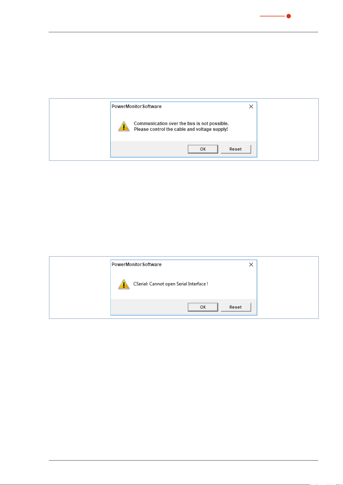
12.2 Testing the Interface
After connecting the devices, the communication between the PC and the measuring system can be
checked. This is what the menu Communication > Free Communication is there for. First of all, the interface is checked by starting the software on the PC.
Possible error message
Fig. 12.2: Possible error message
Reason
• The communication via the bus system is not possible.
Remedy
1. Check the cabling of the devices.
2. Ensure that the voltage supply is connected and turned on (the communication is only possible if the bus
is supplied with 24V direct current voltage).
3. Turn off the voltage supply and turn it on again.
Possible error message (only when operated with the PRIMES converter)
Fig. 12.3: Possible error message
Reason
• The software can not open the preset interface.
Remedy
1. Check whether another software, e.g. a fax software or a parallel running LaserDiagnosticsSoftware LDS,
is just using the interface. A serial port can only be used by one software at a time.
2. Check whether the software opens the right port. After starting the software, the interface used can be
changed in the menu Free Communication. Here, all interfaces available for the software are displayed
(drop-down list Com port).
Revision 02/2019 EN
39

CompactPowerMonitor CPM
35,0(6
12.3 Testing the communication of multiple devices
The communication is checked via the PC by means of the PowerMonitorSoftware PMS. For this purpose, a
certain command is sent to each device. If a device replies as stated in Tab. 12.1 on page40 the communication works without any problems.
Start the PowerMonitorSoftware PMS. Select Communication > Free communication. In the appearing
window the address of the sender (PC) has to be entered in the field FROM, the address of the recipient has
to be entered in the field TO (PRIMES device) and the command is entered in the text field on the right. The
command is confirmed by clicking the button Send. The reply of the device appears below in the bus monitor.
Command line for USB
Address of the sender
Address of the receiver
Fig. 12.4: Menu Free Communication
Device FROM (PC) TO (Device) Command Reply
FocusMonitor 64 161 qr aID FocusMonitor
BeamMonitor 64 144 qr aID BeamMonitor
CompactPowerMonitor CPM 64 113 (112) qr ready Power Monitor
Tab. 12.1: Table for the function control
Text field for the
command input
The command for a query request is qr (query request).
If no reply is received from a device:
1. Turn off the voltage supply and turn it on again. Send the command again.
2. Check the cabling of the device. Are all the plugs connected?
3. A device blocks the PRIMES bus. Turn off the voltage supply and take the faulty device off the bus. Put
the the system back into operation.
4. The PC blocks the PRIMES bus. This is indicated by the red LED “Send“ at the interface converter which
glows permanently. Start the PC again.
40
Revision 02/2019 EN

CompactPowerMonitor CPM
35,0(6
13 Measuring with the PowerMonitor Software PMS
13.1 Safety instructions
DANGER
Serious eye or skin injury due to laser radiation
During the measurement the laser beam is guided on the device, which causes scattered or
directed reflection of the laser beam (laser class 4).
For example, with 10kW of laser power, some 100 W of scattered radiation can occur.
The CompactPowerMonitor CPM must not be operated in any of the available configurations without taking the following precautions.
Please wear safety goggles adapted to the power, power density, laser wave length and
X
operating mode of the laser beam source in use.
Wear suitable protective clothing and protective gloves.
X
Protect yourself from laser radiation by separating protective devices (e.g. by using appro-
X
priate shielding).
DANGER
Serious eye or skin injury due to laser radiation
If the device is moved from its calibrated position, increased scattered or directed reflection
of the laser beam occurs during measuring operation (laser class 4).
When mounting the device, please ensure that it cannot be moved, neither due to an unin-
X
tended push or a pull on the cables or hoses.
DANGER
Fire hazard; Damage/Destruction of the device due to overheating
If the safety interlock is not connected, the unit may overheat and be damaged or catch fire
if there is no water or too low flow.
Connect the laser control’s safety interlock to the device. Check that the safety interlock will
X
switch off the laser properly in case of error.
WARNUNG
Burn hazard; Damage of the absorber – Do not touch
Touching the hot absorber can cause severe burns.
Revision 02/2019 EN
Touching the absorber can lead to burn-in by the laser radiation at the points of contact.
Burn-in lead to damage to the absorber and increase the scattered radiation.
Do not touch the absorber.
X
41

CompactPowerMonitor CPM
35,0(6
13.2 Getting ready for operation
1. Connect the laser control’s safety interlock to the device.
• Check that the safety interlock will switch off the laser properly in case of error.
2. Turn on the voltage supply.
• The green status display (Ready) must light up.
3. Please wait, until the measured value display is illuminated.
4. Turn on the water cooling.
• After a few seconds the red status display (Error) must extinguish.
5. After approx. 2 minutes, the device temperature equals the temperature of the cooling water.
Press the tara button to adjust the offset to zero.
• The CompactPowerMonitor CPM is now ready for operation.
13.3 Starting the software
Start the PowerMonitorSoftware PMS by double-clicking the shortcut on the desktop or by double-clicking the application „PMS.exe“ in the PMS directory. The graphical user interface appears, as displayed in Fig.
13.1 on page43.
When the communication is established, different measuring values are displayed. If no communication is
established, press the Start/Stop button in the upper right corner. If a communication is still not possible
afterwards, proceed as described in chapter 12.2 on page39.
13.4 Perform power measurement
1. Click the button Start.
2. Turn on the laser.
3. The measured power is updated every second on the measured value display of the device (see chapter
Fig. 10.1 on page32) or on the screen of the PC (see chapter 13.6 on page44).
• After about 15 seconds the display reaches about 99 % of the final value.
42
Revision 02/2019 EN

CompactPowerMonitor CPM
35,0(6
13.5 The graphical user interface of the PowerMonitor Software PMS
You can open different dialogue windows via the menu bar.
Fig. 13.1: Menu Selection in the menu bar
File > Settings
Here, a different device address can be entered.
File > Protocol
The determined measuring results can be written in a tab-separated text file. Activate the check box Write
and type in a file name or choose a file. Click OK.
File > Quit
Terminates the software.
Communication > Free communication
Opens the dialogue window for the communication.
Info
Provides information regarding the software.
This operating manual describes the software version v2.57 valid at the point of printing. Due to
the fact that the operating software is continuously developed further, it is possible that a different
version number is printed on the attached PRIMES data medium. The correct function of the device
with the software is still ensured.
Revision 02/2019 EN
43

CompactPowerMonitor CPM
35,0(6
13.6 Measuring value display
The graphical user interface is divided into three display parts (see Fig. 13.2 on page44):
• The numerical display of the current measuring values (window A)
• The temporal development of the laser power or the flow rate or of the cooling water temperature (window B)
• Status window
13.6.1 Window A (Numerical display)
In window A below the large display in Fig. 13.2 on page44: 969 W the following measured values are
displayed:
• The current measuring value
• The minimum value and the maximum value
• The average value (button Average) of the chosen time interval (drop-down list Time)
With the averaging of the power measuring values (Time 10s, 20s, 30s, 50s, max = 90s) a noise
can be reduced, which enables very accurate measurements.
Display area Adjustment area
A
Adjustment area
Control
for window A
B
Time series temperature/water flow
Fig. 13.2: The graphical user interface during a measurement
With option switches Current, Min, Max, Average in the configuration range Control set which measured
value is shown in large digits (see Tab. 13.1 on page44).
Selection Display
Time series power
Adjustment area
Scale
for window B
Status window
Current Display of the current power
Min Display of the minimum power measured
Max Display of the maximum power measured
Average Display of the average value within the chosen measurement duration
Tab. 13.1: Selection for large display of the measured value
44
Revision 02/2019 EN

CompactPowerMonitor CPM
35,0(6
Settings
The maximum duration (Max) for the averaging is 90 seconds.
A possible zero offset can be compensated with the button Use current value as offset or numerically via
the input field Zero level.
13.6.2 Window B (Graphical display)
In window B two time series are displayed.
Time series power
You can scale the y-axis (power) of the window automatically or with fixed values (200W or 500W). In the
setting Automatic the y-axis is scaled with the difference of the measured minimum and maximum value.
Time series temperature/Flow rate
Here, the cooling water flow rate or the input temperature (T
) or the difference temperature (T
in
) between
diff
the input and the output can be controlled. The choice can be made by means of the option switches
in the adjustment area Scale.
• Flow rate
• T
in
• T
diff
Push button clear
Deletes all numerical and graphical displays in the windows.
Select list Time: Frequency
In this select list you choose the duration of the measurement as well as the measurement rate (number of
measurements per time unit). Possible settings:
Measurement
duration
90 s 1 s
10 min 2 s
30 min 2 s
2 h 5 s
10 h 5 s
50 h 10 s
Fig. 13.3: Setting Time: Frequency
Measurement
rate
≙ 1Hz
≙ 0,5Hz
≙ 0,5Hz
≙ 0,2Hz
≙ 0,2Hz
≙ 0,1Hz
13.6.3 Status window
In the bottom right window (Status) of the user interface (see Fig. 13.2 on page44) error messages can
appear in red font. These errors have to be remedied before a measurement.
Revision 02/2019 EN
45

35,0(6
14 Storage
Please note before storing:
NOTICE
Damage/destruction of the device caused by leaking or freezing cooling water
Leaking cooling water can damage the device. Storing the device at temperatures near or
below freezing and without emptying the cooling circuit completely can damage the device.
Empty the lines of the cooling circuit completely.
X
Even when the lines of the cooling circuit have been emptied, a small amount of residual
X
water will remain in the device at all times. This may leak out and end up inside the device.
Close the connector plug of the cooling circuit with the included sealing plugs.
Store the device in the original PRIMES transport box.
X
NOTICE
Damaging/Destruction of the flow rate meter
CompactPowerMonitor CPM
The flow rate meter is not designated for high rotational speed.
Do not use compressed air for emptying the cooling circuit.
X
15 Maintenance and service
The operator is responsible for determining the maintenance intervals for the measuring device.
PRIMES recommends a maintenance interval of 12 months for inspection and validation or calibration.
If the device is used only sporadically, the maintenance interval can also be extended up to 24 months.
16 Measures for the product disposal
Due to the Electrical and Electronic Equipment Act (“Elektro-G“) PRIMES is obliged to dispose PRIMES measuring devices manufactured after August, 2005, free of charge. PRIMES is a registered manufacturer in the
German “Used Appliances Register“ (Elektro-Altgeräte-Register “EAR“) with the number
WEEE-Reg.-Nr. DE65549202.
Provided that you are located in the EU, you are welcome to send your PRIMES devices to the following address where they will be disposed free of charge (this service does not include shipping costs):
PRIMES GmbH
Max-Planck-Str. 2
64319 Pfungstadt
Germany
46
Revision 02/2019 EN

CompactPowerMonitor CPM
35,0(6
17 Declaration of conformity
Revision 02/2019 EN
47

CompactPowerMonitor CPM
35,0(6
18 Technical data
18.1 CPM C-9
Measurement parameters
Max. power range 0.5–9kW
Irradiation time continuous
Wavelength range 800 – 1100nm and 10600nm
Inlet aperture 55mm
1)
Max. power density at beam diameter
Average power density at beam diameter
1)
Accuracy ±3%
Reproducibility ±1.5%
10kW/cm² (Ø<10mm)
5kW/cm² (Ø 10–30 mm)
0,5kW/cm² (Ø 30–55 mm)
5kW/cm² (Ø <10 mm)
5kW/cm² (Ø 10–30mm)
0.5kW/cm² (Ø 30–55 mm)
Time constant <10s
1)
A central beam incidence is assumed.
Supply data
Power supply, DC 24V ±5%, max.0.5A
Min. cooling water pressure 2bar
Max. cooling water pressure 4bar
Recommended cooling water flow rate 8 – 11l/min
Cooling water flow rate (warning level) 4l/min
Cooling water temperature T
2)
Please contact PRIMES in advance in case you intend not to work within this specification.
2)
in
Dew point temperatur <Tin<30°C
Communication
Interfaces RS485/USB
Dimensions and Weights
Dimensions (L x W x H) 180 × 162 × 136mm
Weight (approx.) 5.1kg
Environmental conditions
Operating temperature range 15 – 40°C
Storage temperature range 5 – 50°C
Reference temperature 22°C
Permissible relative humidity (non condensing) 10 – 80%
48
Revision 02/2019 EN

CompactPowerMonitor CPM
35,0(6
18.2 CPM F-1, CPM F-10, CPM F-20, CPM F-30
Measurement parameters CPM F-1 CPM F-10 CPM F-20 CPM F-30
Max. power range 0.1–1,4kW 0.5–10kW 1–20kW 2–30kW
Irradiation time continuous
Wavelength range 800 – 1100nm 800 – 1100nm 800 – 1100nm 800 – 1100nm
Inlet aperture 45mm 90mm 135mm 180mm
Max. power density 1kW/cm² 1kW/cm² 1kW/cm² 1kW/cm²
Average power density 0.5kW/cm² 0.5kW/cm² 0.5kW/cm² 0.5kW/cm²
Accuracy ±3%
Reproducibility ±1.5%
Time constant <10s <10s <10s <15s
Supply data CPM F-1 CPM F-10 CPM F-20 CPM F-30
Power supply, DC 24V ±5%, max.0.5A
Min. cooling water pressure 2bar 3bar 3bar 3bar
Max. cooling water pressure 4bar 4bar 4bar 4bar
Recommended cooling water
flow rate
Cooling water flow rate
(warning level)
Cooling water temperature T
1)
Please contact PRIMES in advance in case you intend not to work within this specification.
Communication CPM F-1 CPM F-10 CPM F-20 CPM F-30
Interfaces RS485/USB
Dimensions and Weights CPM F-1 CPM F-10 CPM F-20 CPM F-30
Dimensions (L x W x H) 180 x 123 x
Weight (approx.) 2.2kg 3.1kg 4.7kg 5.8kg
Environmental conditions CPM F-1 CPM F-10 CPM F-20 CPM F-30
Operating temperature range 15 – 40°C
Storage temperature range 5 – 50°C
Reference temperature 22°C
Permissible relative humidity
(non condensing)
in
1 – 2l/min 8 – 11l/min 15 – 23l/min 25 – 35l/min
0,5l/min 4l/min 8l/min 15l/min
1)
71mm
Dew point temperatur <Tin<30°C
180 x 162 x
71mm
260 × 162 x
113mm
10 – 80%
260 × 220 x
113mm
Revision 02/2019 EN
49
35,0(6
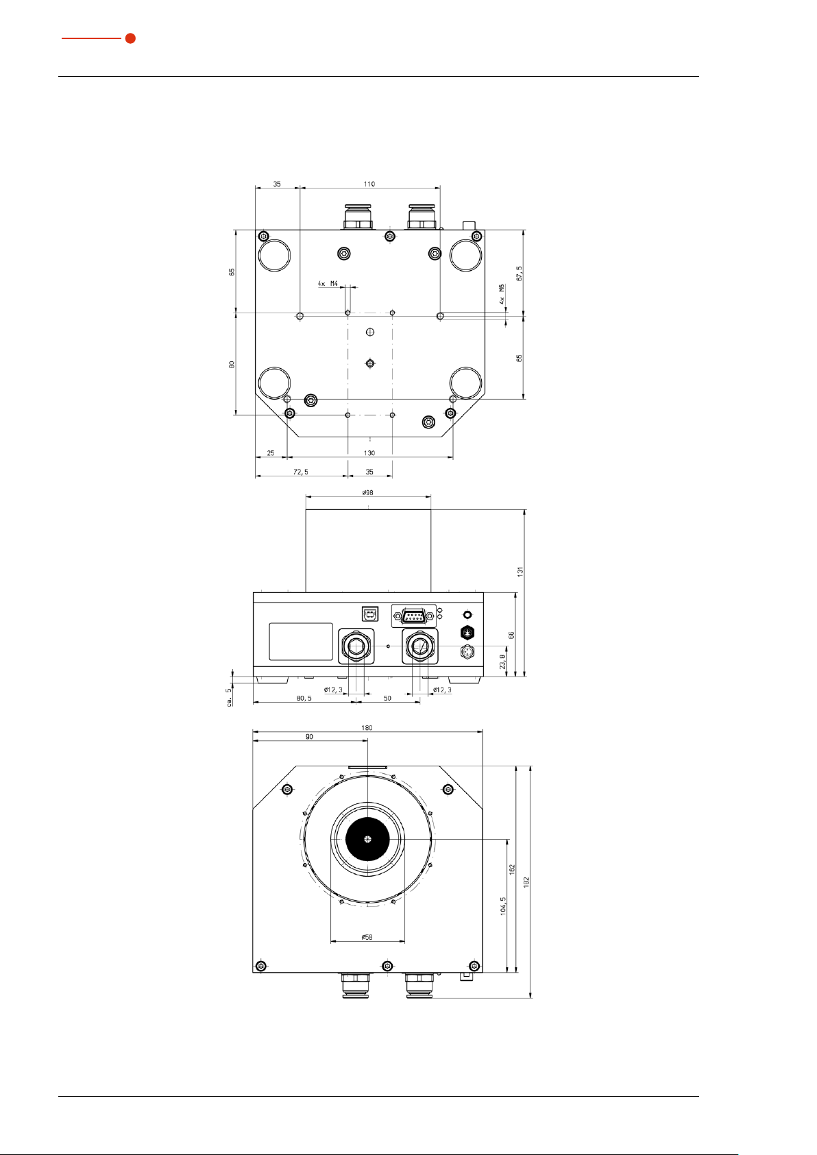
19 Dimensions
19.1 Dimensions CPM C-9
CompactPowerMonitor CPM
All dimensions in mm (general tolerance ISO 2768-v)
50
Revision 02/2019 EN

CompactPowerMonitor CPM
35,0(6
19.2 Dimensions CPM F-1
All dimensions in mm (general tolerance ISO 2768-v)
Revision 02/2019 EN
51

35,0(6
19.3 Dimensions CPM F-10
CompactPowerMonitor CPM
All dimensions in mm (general tolerance ISO 2768-v)
52
Revision 02/2019 EN

CompactPowerMonitor CPM
35,0(6
19.4 Dimensions CPM F-20
All dimensions in mm (general tolerance ISO 2768-v)
Revision 02/2019 EN
53

35,0(6
19.5 Dimensions CPM F-30
CompactPowerMonitor CPM
All dimensions in mm (general tolerance ISO 2768-v)
54
Revision 02/2019 EN
CompactPowerMonitor CPM
35,0(6
20 Appendix
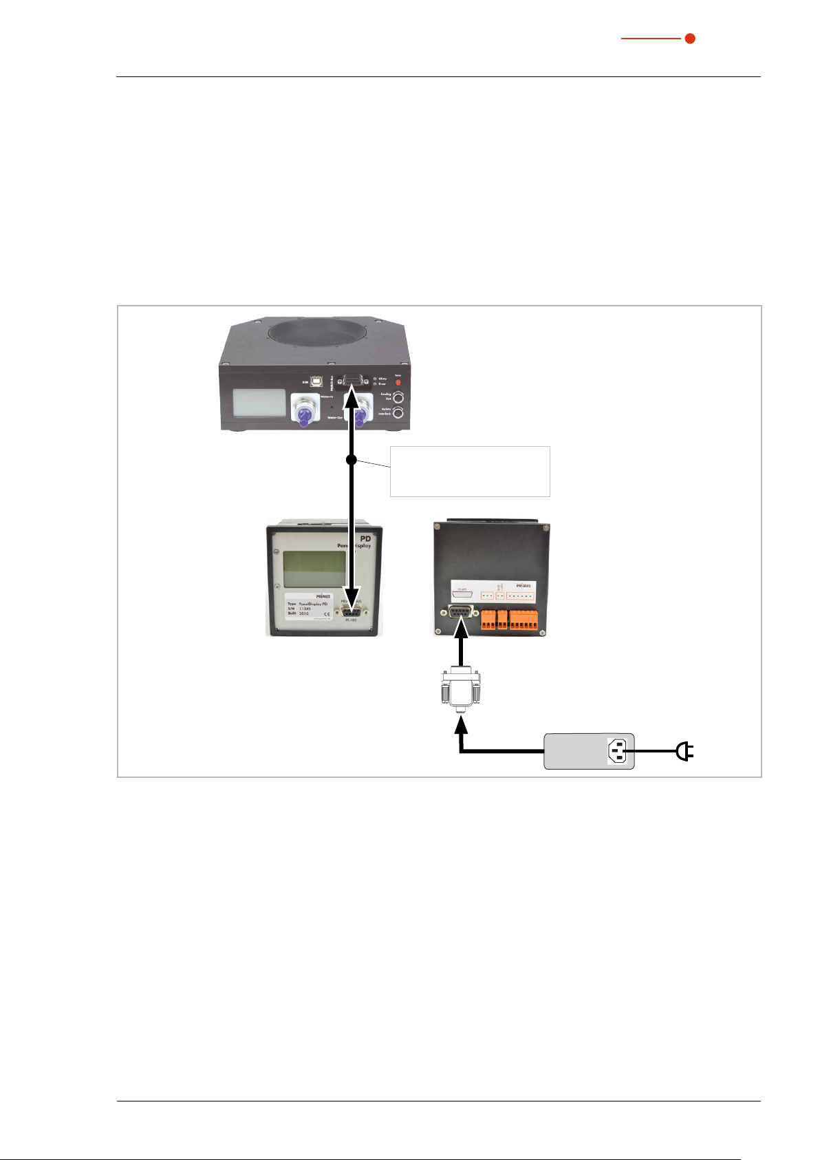
20.1 Operation of the CompactPowerMonitor with PanelDisplay (without PC)
By option there is a external control display (PanelDisplay, Order-No. 130-005-003) available for the operation of the system. The display is operated via the standard PRIMES bus and therefore enables the reading
from a greater distance from the measuring position without a PC.
1. Please connect the display and the CPM by the 9-pole D-Sub cable for the PRIMES RS485 bus (on the
front or on the rear side).
2. Connect the power supply unit via the adapter to the 9pin D-Sub socket (RS485) of the PanelDisplay.
CPM
PRIMES connection cable
PanelDisplay
Fig. 20.1: Connecting the CompactPower Monitor CPM to the Panel Display
plug/plug
L
=20m
max
Adapter
PRIMES power supply
Revision 02/2019 EN
55
35,0(6
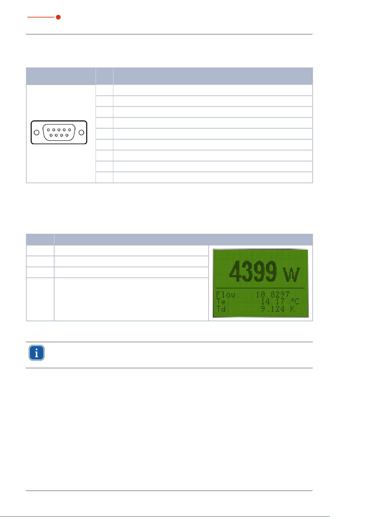
20.1.1 Pin assignment 9-pole D-Sub socket
CompactPowerMonitor CPM
D-Sub socket, 9 pin
(top view, plug-in side)
15
69
Tab. 20.1: Pin assignment D-Sub socket on the PanelDisplay
Pin Function
1 Ground
2 RS485 (+)
3 +24V
4 Not assigned
5 Not assigned
6 Ground
7 RS485 (–)
8 +24V
9 Not assigned
20.1.2 Measurement display
The PanelDisplay reflects the display of the CompactPowerMonitor CPM. The PanelDisplay shows the following measurement values:
Display Meaning
W Laser power in W
Flow Water flow rate in l/min
Te Water temperature at the entrance in °C
Td Temperature difference between water input and output in
Tab. 20.2: Meaning of the measured display
Kelvin (a temperature difference of 1K corresponds to a temperature difference of 1°C).
For the operation with the PowerMonitorSoftware via PC, you have to change the operating mode
of the display from “Active” to “Passive”. Further information can be found in the operating manual
„Panel Display“, chapter „Operating Mode“.
56
Revision 02/2019 EN

CompactPowerMonitor CPM
35,0(6
20.2 Mounting position of a CompactPowerMonitor CPM with oval wheel meter
Please note during installation, that the axis of the oval wheel meter must always be horizontal.
Oval wheel meter axis
Fig. 20.2: Position of the oval wheel meter axis
Correct mounting position
The device can either stand on its
feet (A) or the connections and display are in an upright position (B)
Incorrect mounting position
The flat side of the oval wheel
meter must not point downwards
(to the table).
A B
Tab. 20.3: Mounting position of the CompactPowerMonitor CPM with oval wheel meter
Revision 02/2019 EN
For a continuous operation, the oval wheel meter axis has to be positioned horizontally. For a short
period of time (a few hours per year) the CPM with oval wheel meter can be operated in the “incorrect“ installation position without immediately causing damages to the device. Longer operation
periods, however, may wear off the flow rate sensor.
57
35,0(6
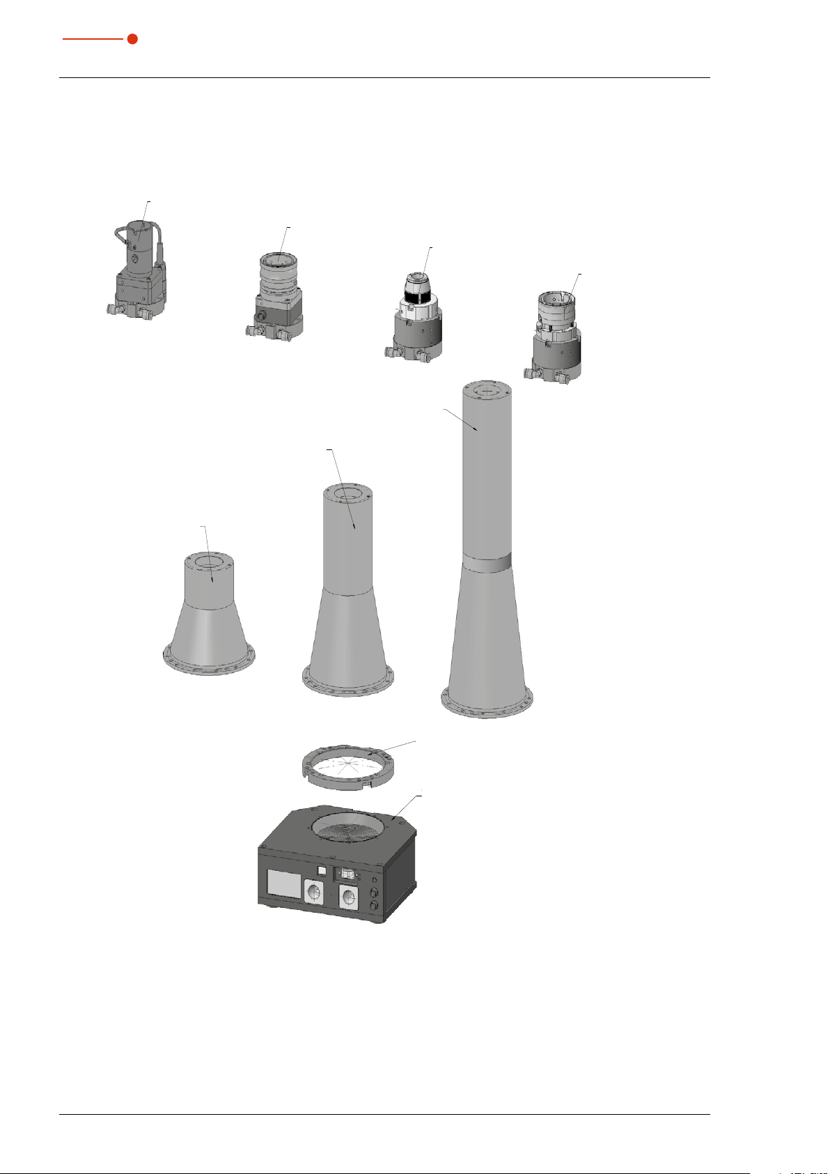
20.3 Accessories fiber adapter
134-001-001
CPM F -10
136-002-031
CPM Fiber Connector LLK-D
136-002-019
Adapter Ring to Fiber Adapter CPM F-10
136-002-044
CPM F-10 DOME 216,5 mm
136-002-046
CPM F-10 DOME 346,5 mm
136-002-032
CPM Fiber Connector LLK-B
136-002-045
CPM F-10 DOME 111,5 mm
136-002-033
CPM Fiber Connector QD
136-002-030
CPM Fiber Connector QBH
Example: Fiber adapter and dome for CPM F-10
CPM Fiber connector LLK-B
136-002-032
CPM Fiber connector LLK-D
136-002-031
CPM F-10 Dome 346,5mm
136-002-046
CompactPowerMonitor CPM
CPM Fiber connector QBH
136-002-030
CPM Fiber connector QD
136-002-033
CPM F-10 Dome 111,5mm
136-002-045
CPM F-10 Dome 216,5mm
136-002-044
Adapter ring to fiber adapter CPM F-10
136-002-019
CPM F-10
134-001-001
For information about other fiber adapters for the CompactPowerMonitor CPM, see the PRIMES documentation “Installation fiber adapter”.
58
Revision 02/2019 EN
 Loading...