


35,0(6
Operating Manual
Translation of the original instructions
BeamMonitor BM+
BM+ 60, BM+ 100
LaserDiagnosticsSoftware LDS
Revision 02/2019 EN


BeamMonitor BM+
35,0(6
IMPORTANT!
READ CAREFULLY BEFORE USE.
KEEP FOR FUTURE USE.
Revision 02/2019 EN
3

35,0(
6
BeamMonitor BM+
Table of contents
1 Basic safety instructions 7
2 Symbol explanations 9
3 About this operating manual 10
4 Conditions at the installation site 10
5 Introduction 11
5.1 System description .................................................................................................................11
5.2 Measuring principle .................................................................................................................11
5.3 Short overview installation .......................................................................................................12
6 Transport 13
7 Installation 13
7.1 Safety instructions ................................................................................................................... 13
7.2 Preparation .............................................................................................................................14
7.3 Installation position .................................................................................................................. 14
7.4 Align the BeamMonitor BM+ ...................................................................................................15
7.5 Install the BeamMonitor BM+ ..................................................................................................15
7.5.1 Install the BeamMonitor BM+ 60 ............................................................................... 16
7.5.2 Install the BeamMonitor BM+ 100 ............................................................................. 17
8 Electrical connections 18
8.1 Connections ............................................................................................................................ 18
8.2 Pin assignment .......................................................................................................................19
8.2.1 Power supply ............................................................................................................ 19
8.2.2 PRIMES bus RS485 .................................................................................................. 19
8.3 Connection to the PC and establishing the power supply ........................................................ 20
8.4 Connection of the BeamMonitor BM+ and PowerMonitor PM48/100 to the PC .....................21
9 Status display 22
10 Measuring 23
10.1 Safety instructions ................................................................................................................... 23
10.2 Connect the BeamMonitorBM+ with the LaserDiagnosticsSoftwareLDS................................24
10.2.1 Connect device ......................................................................................................... 24
10.2.2 Change the network address of a connected device .................................................24
10.3 Performing a single planes measurement ................................................................................25
10.3.1 Selecting the measuring mode single planes ............................................................. 25
10.3.2 Performing a manual or automatic beam search (Device control > Settings) ...........26
10.3.3 Configuring advanced settings (Device control > Advanced) ..................................27
10.3.4 Starting measurement ...............................................................................................28
10.3.5 Measurement results display .....................................................................................28
11 Troubleshooting 29
12 Maintenance and service 29
13 Product disposal measures 29
14 Declaration of conformity 30
4
Revision 02/2019 EN

BeamMonitor BM+
15 Technical data 31
16 Dimensions 32
16.1 BeamMonitor BM+ 60 ............................................................................................................. 32
16.2 BeamMonitor BM+ 100 ........................................................................................................... 33
17 Appendix 34
17.1 System control (option) ...........................................................................................................34
17.2 Variety of detectors .................................................................................................................34
17.3 Replace the detector ............................................................................................................... 35
17.3.1 Remove cover ...........................................................................................................35
17.3.2 Disassemble the detector .........................................................................................35
17.3.3 Assemble the detector .............................................................................................. 37
17.3.4 Replace cover ........................................................................................................... 37
35,0(6
Revision 02/2019 EN
5

35,0(
6
PRIMES - The Company
PRIMES manufactures measuring devices used to analyze laser beams. These devices are employed for
the diagnostics of high-power lasers ranging from CO
length range from infrared through to near UV is covered, offering a wide variety of measuring devices to
determine the following beam parameters:
• Laser power
• Beam dimensions and position of an unfocused beam
• Beam dimensions and position of a focused beam
• Beam quality factor M²
PRIMES is responsible for both the development, production, and calibration of the measuring devices. This
guarantees optimum quality, excellent service, and a short reaction time, providing the basis for us to meet all
of our customers’ requirements quickly and reliably.
lasers and solid-state lasers to diode lasers. A wave-
2
BeamMonitor BM+
PRIMES GmbH
Max-Planck-Str. 2
64319 Pfungstadt
Germany
Tel +49 6157 9878-0
info@primes.de
www.primes.de
6
Revision 02/2019 EN

BeamMonitor BM+
35,0(6
1 Basic safety instructions
Intended Use
The BeamMonitor BM+ has been designed exclusively for measurements carried out in or near the optical
path of high-power lasers. Please observe and adhere to the specifications and limit values given in chapter15, „Technical data“, on page31. Other uses are considered to be improper. The information contained
in this operating manual must be strictly observed to ensure proper use of the device.
Using the device for unspecified use is strictly prohibited by the manufacturer. By usage other than intended
the device can be damaged or destroyed. This poses an increased health hazard up to fatal injuries. When
operating the device, it must be ensured that there are no potential hazards to human health.
The device itself does not emit any laser radiation. During the measurement, however, the laser beam is
guided onto the device which causes reflected radiation (laser class 4). That is why the applying safety regulations are to be observed and necessary protective measures need to be taken.
Observing applicable safety regulations
Please observe valid national and international safety regulations as stipulated in ISO/CEN/TR standards as
well as in the IEC-60825-1 regulation, in ANSI Z 136 “Laser Safety Standards” and ANSI Z 136.1 “Safe Use
of Lasers”, published by the American National Standards Institute, and additional publications, such as the
“Laser Safety Basics”, the “LIA Laser Safety Guide”, the “Guide for the Selection of Laser Eye Protection”
and the “Laser Safety Bulletin”, published by the Laser Institute of America, as well as the “Guide of Control
of Laser Hazards” by ACGIH.
Necessary safety measures
DANGER
Serious eye or skin injury due to laser radiation
Depending on the measuring principle used, the laser beam is reflected at the measuring tip
(laser class4). The reflected beam is usually not visible.
In measurement mode, a safety distance of one meter to the BeamMonitor BM+ must be
X
maintained even when wearing safety goggles and safety clothing.
Please take the following precautions.
X
If people are present within the danger zone of visible or invisible laser radiation, for example near laser
systems that are only partly covered, open beam guidance systems, or laser processing areas, the following
safety measures must be implemented:
• Please wear safety goggles (OD 6) adapted to the power, power density, laser wave length and operat-
ing mode of the laser beam source in use.
• Depending on the laser source, it may be necessary to wear suitable protective clothing or protective
gloves.
• Protect yourself from direct laser radiation, scattered radiation, and beams generated from laser radiation
(by using appropriate shielding walls, for example, or by weakening the radiation to a harmless level).
• Use beam guidance or beam absorber elements that do not emit any hazardous substances when they
come in to contact with laser radiation and that can withstand the beam sufficiently.
• Install safety switches and/or emergency safety mechanisms that enable immediate closure of the laser
shutter.
• Ensure that the device is mounted securely to prevent any movement of the device relative to the beam
axis and thus reduce the risk of scattered radiation. This in the only way to ensure optimum performance
during the measurement.
Revision 02/2019 EN
7

35,0(
6
Employing qualified personnel
The device may only be operated by qualified personnel. The qualified personnel must have been instructed
in the installation and operation of the device and must have a basic understanding of working with highpower lasers, beam guiding systems and focusing units.
Conversions and modifications
The device must not be modified, neither constructionally nor safety-related, without our explicit permission.
The device must not be opened e.g. to carry out unauthorized repairs. Modifications of any kind will result in
the exclusion of our liability for resulting damages.
Liability disclaimer
The manufacturer and the distributor of the measuring devices do not claim liability for damages or injuries
of any kind resulting from an improper use or handling of the devices or the associated software. Neither the
manufacturer nor the distributor can be held liable by the buyer or the user for damages to people, material
or financial losses due to a direct or indirect use of the measuring devices.
BeamMonitor BM+
8
Revision 02/2019 EN

BeamMonitor BM+
2 Symbol explanations
The following symbols and signal words indicate possible residual risks:
DANGER
Means that death or serious physical injuries will occur if necessary safety precautions are not
taken.
WARNING
Means that death or serious physical injuries may occur if necessary safety precautions are not
taken.
CAUTION
Means that minor physical injury may occur if necessary safety precautions are not taken.
NOTICE
35,0(6
Means that property damage may occur if necessary safety precautions are not taken.
The following symbols indicating requirements and possible dangers are used on the device:
Hand injuries warning
Read and observe the operating instructions and safety guidelines before startup!
Further symbols that are not safety-related:
Here you can find useful information and helpful tips.
With the CE designation, the manufacturer guarantees that its product meets the requirements of
the relevant EC guidelines.
Call for action
X
Revision 02/2019 EN
9

35,0(
6
BeamMonitor BM+
3 About this operating manual
This documentation describes the installation and configuration of the BeamMonitor BM+ and the execution
of measurement with the PRIMES LaserDiagnosticsSoftware LDS.
The LaserDiagnosticsSoftware LDS must be installed on the PC for measuring operation of the BeamMonitor
BM+. The basic version of the LaserDiagnosticsSoftware LDS is included in the scope of delivery for the
device.
For a detailed description of the software installation, file management and evaluation of the measured data,
please refer to the separate operating manual LaserDiagnosticsSoftware LDS.
4 Conditions at the installation site
• The device must not be operated in a condensing atmosphere.
• The ambient air must be free of organic gases.
• Protect the device from splashes of water and dust.
• Operate the device in closed rooms only.
DANGER
Fire and explosion hazards due to scattered or directed laser radiation
When the BeamMonitor BM+ is being operated, the irradiation must be fully absorbed behind the measurement zone. Fire bricks or other partly-absorbing surfaces are not suitable.
Use an adequate absorber. Dependent on the application, PRIMES offers suitable absorbers,
X
such as the PowerMonitor PM48/100.
Don’t store any flammable materials or highly flammable substances at the measuring loca-
X
tion.
10
Revision 02/2019 EN

BeamMonitor BM+
35,0(6
5 Introduction
5.1 System description
The BeamMonitorBM+ is an opto-mechanical scanning measurement system for analyzing continuous irradiation. The device measures the power density distribution of the raw beam. The LaserDiagnosticsSoftware
LDS uses this to calculate the beam position, beam dimensions, beam symmetry, and power density distribution.
The BeamMonitor BM+ can be mounted in any desired position.
5.2 Measuring principle
The BeamMonitorBM+ is used to analyze the unfocused, continual, high-power laser beam of CO2 or NIR
lasers.
A rotating measuring tip scans the laser beam along the x-axis. During this process, the very small mirror in
the measuring tip separates out a small part of the radiation.
The horizontal carrier moves the measuring tip along the y-axis in order to measure the beam properties of
the laser beam on the x-y-plane. Another mirror finally guides the measurement signal to the detector.
y
x
Measuring tip
with mirror
y
Laser beam
Fig. 5.1: Optomechanical design of the BeamMonitor BM+
Using various detectors with varying degrees of sensitivity, the BeamMonitor BM+ can be adapted to meet
the unique demands of beam diagnostics within a broad wavelength and power density range.
x
Mirror
Detector
Horizontal carrier
Revision 02/2019 EN
11

35,0(
6
5.3 Short overview installation
BeamMonitor BM+
1. Installing the LaserDiagnosticsSoftware LDS on the computer
• Software is part of the scope of delivery
2. Taking safety precautions Chapter 1 on page 7
3. Prepare Installation
• Observe safety instructions
• Make preparations
• Set installation position
4. Electrical connection
• Establish voltage supply
5. Connect with the computer
• Via Ethernet or LAN
See separate Operating Manual
of the LaserDiagnosticsSoftware
LDS
Chapter 7 on page 13
Chapter 8 on page 18
Chapter 8.3 on page 20
6. Connect with the PowerMonitor PM48/100
• Via RS485
7. Perform the measurement
• Observe safety instructions
• Perform a sample measurement
Chapter 8.4 on page 21
Chapter 10 on page 23
12
Revision 02/2019 EN

BeamMonitor BM+
35,0(6
6 Transport
NOTICE
Damage/Destruction of the device
Optical components may be damaged if the device is subjected to hard shocks or is allowed
to fall.
Handle the device carefully when transporting or installing it.
X
To avoid contamination, cover the apertures with the provided lid or optical tape.
X
Only transport the device in the original PRIMES transport box.
X
7 Installation
7.1 Safety instructions
Areas on the device that could be particularly hazardous for hand injuries are marked with the following pictogram:
Hand injuries warning
CAUTION
Risk of injury caused by rotating parts
The measuring tip of the BeamMonitor BM+ rotates at high speed during the measuring
operation.
Do not reach into or hold any objects into the beam entrance of the device (see Fig. 7.1 on
X
page 13).
Rotating measuring tip
Fig. 7.1: Danger due to the rotating measuring tip using the example of the BM+ 100
Revision 02/2019 EN
13
35,0(
6
BeamMonitor BM+
7.2 Preparation
Check the space available before mounting the device, especially the required space for the connection cables.
The device must be firmly assembled and must be mounted with screws (see chapter 7.5 on page 15).
DANGER
Fire and explosion hazards due to scattered or directed laser radiation
When the BeamMonitor BM+ is being operated, the irradiation must be fully absorbed behind the measurement zone. Fire bricks or other partly-absorbing surfaces are not suitable.
Use an adequate absorber. Dependent on the application, PRIMES offers suitable absorbers,
X
such as the PowerMonitor PM48/100.
Don’t store any flammable materials or highly flammable substances at the measuring loca-
X
tion.
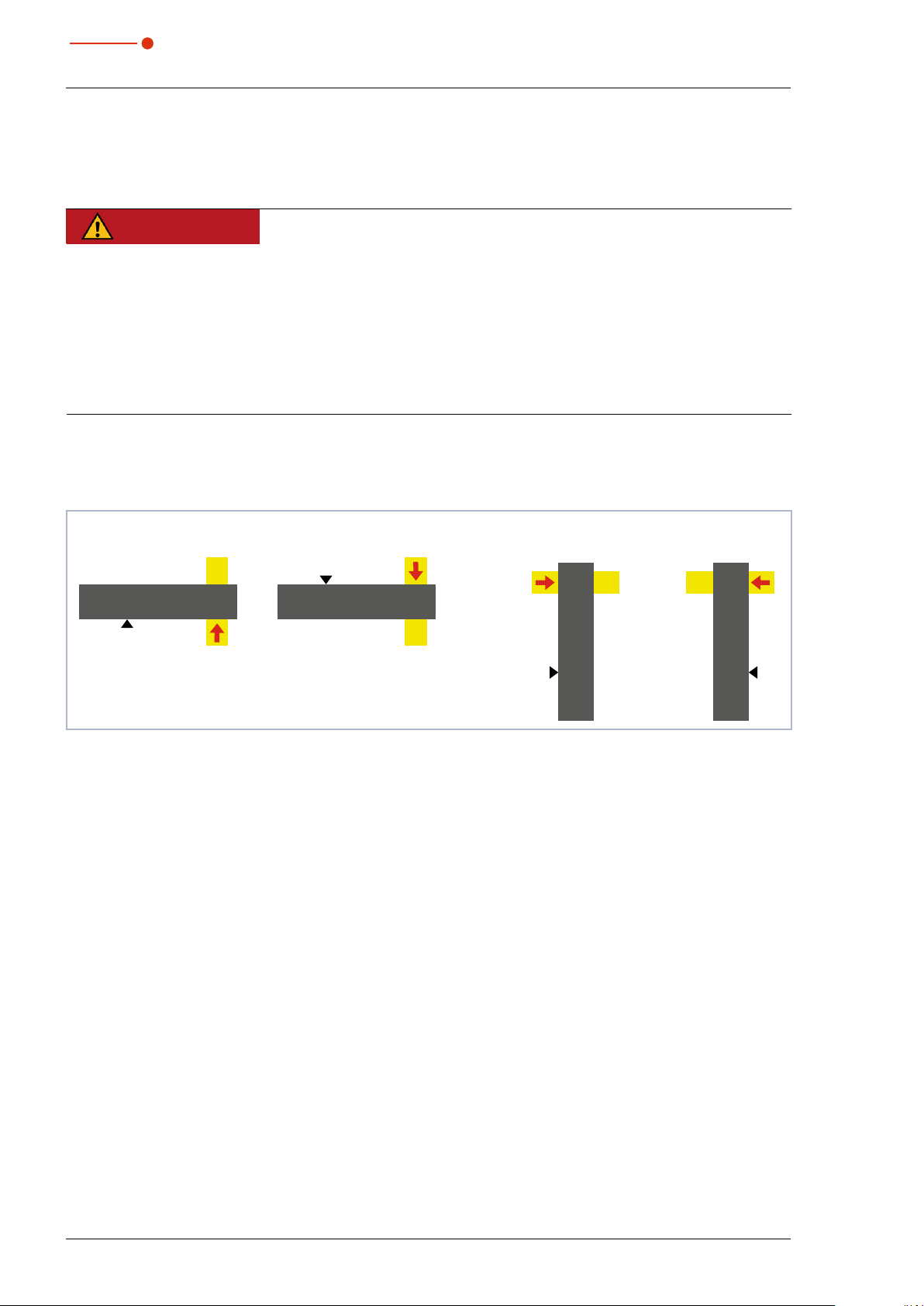
7.3 Installation position
The BeamMonitor BM+ can also be mounted horizontally or vertically.
Horizontal installation Vertical installation
Mounting surface
BeamMonitor BM+
Mounting surface
Beam incidence
Fig. 7.2: Installation positions of the BeamMonitor BM+
BeamMonitor BM+
Beam incidence
Beam incidence
BeamMonitor BM+
Mounting surface
Beam incidence
BeamMonitor BM+
Mounting surface
14
Revision 02/2019 EN
BeamMonitor BM+
7.4 Align the BeamMonitor BM+
For the BeamMonitorBM+, the beam must enter vertically to the x-y-plane.
The laser beam must hit the inlet aperture in the middle.
DANGER
Serious eye or skin injury due to laser radiation
If the ratio of the laser beam diameter to the aperture diameter is too large, increased scattered or directed reflection of the laser beam (laser class 4) will occur during measuring
operation. The housing of the BeamMonitor BM+ can heat up.
The laser beam diameter must not exceed 0.7 times the aperture diameter.
X
Especially in case of laser with high beam quality, the laser beam diameter must not exceed
X
0.6 times the aperture diameter. Otherwise, a falsification of the measuring results due to the
cutting off of border fields is to be expected.
Especially when it comes to the determination of radii according to the second moment
method, measuring errors are otherwise possible.
7.5 Install the BeamMonitor BM+
35,0(6
DANGER
Serious eye or skin injury due to laser radiation
If the device is moved from its calibrated position, increased scattered or directed reflection
of the laser beam occurs during measuring operation (laser class 4).
Mount the device so that it cannot be moved by an unintentional knock or cables being
X
pulled accidentally.
NOTICE
Damage/Destruction of the device
Too long fastening screws can damage internal components in the device.
The fastening screws must not be screwed in more than 10mm into the housing.
X
There are four threaded holes M6 in the mounting surface of the housing for assembly on a support bracket
provided by the customer (see Fig. 7.3 on page 16 and Fig. 7.4 on page 17).
Please use at least four screws to fasten the device. The total length of the screws depends on the dimensions of the customer’s support bracket. The dimensioned arrangement of the mounting holes is specified in
chapter16, „Dimensions“, on page32.
Revision 02/2019 EN
15

35,0(
6
7.5.1 Install the BeamMonitor BM+ 60
M6 M6
BeamMonitor BM+
M6 M6
Fig. 7.3: Mounting holes on the BeamMonitor BM+ 60
16
Revision 02/2019 EN

BeamMonitor BM+
7.5.2 Install the BeamMonitor BM+ 100
35,0(6
M6
M6
Fig. 7.4: Mounting holes on the BeamMonitor BM+ 100
M6
M6
Revision 02/2019 EN
17

35,0(
6
BeamMonitor BM+
8 Electrical connections
The BeamMonitor BM+ requires a voltage supply of 24V±5% (DC) for the operation. A suitable power supply is included in the scope of delivery.
Data is transmitted between the BeamMonitor BM+ and PC via the Ethernet connection.
Another device, such as a PowerMonitor PM48/100, can be connected to the BeamMonitorBM+ via the
RS485 interface (PRIMES bus). The signal from the PowerMonitor PM48/100 is transmitted through the
BeamMonitor BM+ to the PC via the Ethernet interface. The additional measuring device is powered by the
power supply of the BeamMonitor BM+.
Please use only the provided PRIMES power supply and connection lines.
Please ensure that all electrical connections have been established and switch the device on before
starting the LaserDiagnosticsSoftware LDS.
The BeamMonitor BM+ serves as a dongle for the software on the computer in order to enable
certain software functions.
8.1 Connections
Status displayOn/Off switch
Power supply connection
Fig. 8.1: BeamMonitor BM+ connections using the example of the BM+ 100
Ethernet
RS485
18
Revision 02/2019 EN

BeamMonitor BM+
8.2 Pin assignment
8.2.1 Power supply
Harting M12-P-PCB-THR-2PC-5P-LCOD-M-STR
35,0(6
23
4
FE
Tab. 8.1: Connection socket for the power supply
1
Pin Function
1 +24V
2 Not assigned
3 GND
4 Not assigned
5 FE (functional earth)
8.2.2 PRIMES bus RS485
Pin arrangement D-sub socket, 9-pin (view of plug-in side)
Pin Function
1 GND
5
1
69
2 RS485 (+)
3 +24V
4 Not assigned
5 Not assigned
6 GND
Tab. 8.2: D-sub socket, PRIMES bus
7 RS485 (–)
8 +24V
9 Not assigned
Revision 02/2019 EN
19

35,0(
6
8.3 Connection to the PC and establishing the power supply
BeamMonitor BM+
or
L
L
Max
= 1.8m
= 2.0m
Max
BeamMonitor BM+
Crossover cable
PRIMES power supply
Ethernet
PC
Fig. 8.2: Connection of BeamMonitor BM+ using the example of the BM+ 100
Connect the BeamMonitor BM+ to the PC via a crossover cable or to the network via a patch cable.
Ethernet
LAN
Patch cable
20
Revision 02/2019 EN

BeamMonitor BM+
35,0(6
8.4 Connection of the BeamMonitor BM+ and PowerMonitor PM48/100 to the PC
For full absorption of the radiation behind the measurement zone, you can use the PRIMES PowerMonitor
PM48/100. The water-cooled PowerMonitor PM48/100 will show you the laser power, water flow rate, and
water temperature.
PRIMES power supply
L
= 1.8m
Max
BeamMonitor BM+
L
= 10m
Max
Max
= 2.0mL
PowerMonitor PM48/100
PRIMES bus
RS485
Ethernet
Crossover cable
PC
Fig. 8.3: Connection of the BeamMonitor BM+ using the example of the BM+ 100 and PowerMonitor PM48/100 to
the PC
NOTICE
Damage/Destruction of the device due to overvoltage
When disconnecting the electric cables during operation (when the supply voltage is connected), voltage peaks can be generated that could destroy the communication modules of
the measuring devices.
Turn off the power supply before disconnecting the bus cables.
X
Only ever use one PRIMES power supply when connecting several devices.
Revision 02/2019 EN
21

35,0(
6
BeamMonitor BM+
9 Status display
The status display consists of a light ring that indicates different states of the BeamMonitorBM+ with different colors and static or rotating lights.
Color Lighting state Meaning
White The entire ring illuminates The supply voltage is connected
Yellow Rotating light The measuring tip rotates.
Red Rotating light The measuring tip rotates and the y-axis is
Tab. 9.1: States of the status display
moved. The measurement is in progress.
22
Revision 02/2019 EN

BeamMonitor BM+
10 Measuring
10.1 Safety instructions
DANGER
Serious eye or skin injury due to laser radiation
Depending on the measuring principle used, the laser beam is reflected at the measuring tip
(laser class4). The reflected beam is usually not visible.
Please wear safety goggles (OD6) adapted to the power, power density, laser wave length
X
and operating mode of the laser beam source in use.
Wear suitable protective clothing and protective gloves.
X
Protect yourself from laser radiation by separating protective devices (e.g. by using appro-
X
priate shielding).
In measurement mode, a safety distance of one meter to the BeamMonitorBM+ must be
X
maintained even when wearing safety goggles and safety clothing.
35,0(6
DANGER
Serious eye or skin injury due to laser radiation
If the device is moved from its calibrated position, increased scattered or directed reflection
of the laser beam occurs during measuring operation (laser class 4).
Mount the device so that it cannot be moved by an unintentional knock or cables being
X
pulled accidentally.
DANGER
Fire and explosion hazards due to scattered or directed laser radiation
When the BeamMonitor BM+ is being operated, the irradiation must be fully absorbed behind the measurement zone. Fire bricks or other partly-absorbing surfaces are not suitable.
Use an adequate absorber. Dependent on the application, PRIMES offers suitable absorbers,
X
such as the PowerMonitor PM48/100.
Don’t store any flammable materials or highly flammable substances at the measuring loca-
X
tion.
CAUTION
Risk of injury caused by rotating parts
The measuring tip of the BeamMonitor BM+ rotates at high speed during the measuring
operation.
Do not reach into or hold any objects into the beam entrance of the device (see Fig. 7.1 on
X
page 13).
Revision 02/2019 EN
23

35,0(
6
BeamMonitor BM+
10.2 Connect the BeamMonitorBM+ with the LaserDiagnosticsSoftwareLDS
10.2.1 Connect device
1. Switch on the BeamMonitorBM+.
The operating mode is shown in the
status display (see chapter 9 on page
22).
2. Start the LaserDiagnosticsSoftware
LDS.
3. Click on the Devices tab.
4. Click on the + Connect to device
button under the tab.
The Connections window appears.
5. Click on the desired device.
6. Click on the Connect to device but-
ton.
10.2.2 Change the network address of a connected device
Proceed as follows in order to assign a different IP address to a connected device:
1. Right-click on the device and select
the Device settings menu point.
2. Enter in the desired IP address or
use the Use DHCP option and confirm the entry with OK.
3. Turn the BeamMonitor BM+ off and
on again.
24
Revision 02/2019 EN

BeamMonitor BM+
35,0(6
10.3 Performing a single planes measurement
This chapter aims to provide some basic information as you get to know the BeamMonitor BM+, discussing
the example of a measurement with the LaserDiagnosticsSoftware LDS.
For a detailed description of the software installation, file management and evaluation of the measured data,
please refer to the separate operating manual LaserDiagnosticsSoftware LDS.
10.3.1 Selecting the measuring mode single planes
1. Connect the device according to
chapter 10.2 on page 24 with the
LaserDiagnosticsSoftware LDS.
TheBeamMonitor BM+ is established
as a connected device.
2. Click on the Scanner function.
The Device control menu opens.
3. Click on the Measuring mode dropdown list.
4. Click on the entry Single planes.
The corresponding Device control
opens.
The Single planes tool bench opens
with the following tools:
• Caustic analysis
• Plane analysis
Drop-down list Measuring mode
Measuring mode Single planes
Revision 02/2019 EN
25

35,0(
6
10.3.2 Performing a manual or automatic beam search (Device control > Settings)
Manual beam search
1. Click on the Settings tab.
2. Start the measurement according to
chapter 10.3.4 on page 28.
• The beam is displayed in the measurement window.
• Since the beam should fill approx.
one third of the measuring window,
change the measuring window size.
Settings of the measuring window size
X Enter the window size in mm.
• Alternatively, you can drag a measurement window while holding down the
left mouse button.
• With pressed, right mouse button you
can move the measuring window.
• With the button Reset parameters
the settings of the measuring window
are reset.
3. Start the measurement according to
chapter 10.3.4 on page 28.
• The beam is displayed in the measurement window.
• If the beam can not be displayed, increase the laser power and/or adjust
the gain.
BeamMonitor BM+
Automatic beam search
When activating the checkbox autom.
Measuring window, the laser beam is
searched automatically and an optimally
adjusted measuring window is placed
around the beam.
1. Mark the checkbox autom. Mea-
surement window.
2. Start the measurement according to
chapter 10.3.4 on page 28.
• The beam is displayed in the measurement window.
• If the beam can not be displayed, increase the laser power and/or adjust
the gain.
Once the beam has been located, you
can review the beam parameters in the
window Plane Analysis, under the Re-
sults tab.
Accurate beam parameters are indicated
by a green check mark.
Setting for manual or automatic gain
X Mark the checkbox autom. Gain.
• If the check mark is removed next to
autom. Gain, you can enter the value
manually.
26
Revision 02/2019 EN

BeamMonitor BM+
10.3.3 Configuring advanced settings (Device control > Advanced)
1. Click on the Advanced tab.
Resolution of the measurement window
2. Enter the number of Pixel in x/y for
the measurement.
Wave length
3. Select the Calibrated wavelength in
nm of your BeamMonitor BM+.
4. Enter the Used wavelength in nm of
the laser.
Laser power and focal length (option)
The input of the laser power and focal
length is needed for the calculation of the
beam quality factor M², the power density
and the raw beam diameter, etc.
5. Enter the laser Power P in W.
6. For a built-in focusing optics, enter
the Focal length of focusing optic
in mm.
35,0(6
Averaging
By placing a check mark next to Averaging, you can select various algorithms for
averaging the measuring values:
Analysis of series measurements. Averaging algorithms: Average value, value of the
maximum pixel and value of the maximum
trace.
7. Enter the Number of averaged
planes.
Revision 02/2019 EN
27

35,0(
6
10.3.4 Starting measurement
1. Follow the safety instructions in chapter chapter 10.1 on page 23.
2. Turn on the laser.
3. Click on the Start button.
The progress of the measurement
is shown in the displays Measuring
plane and Measurement completed:
Measuring plane
During the display, the plane or, depending on the setting, several planes are
measured with the optimal measurement
parameters.
Measurement completed
The measurement has been completed.
4. Turn off the laser.
5. Click on the Stop Rotation button to
turn off the measurement tip rotation.
Averaging
The information shows measured planes
analyzed in order to average a measuring
value.
BeamMonitor BM+
10.3.5 Measurement results display
The measurement results are shown in the opened tools after the measurement is completed (see below).
A detailed description of the tools and the assessment of the measuring results can be found in the separate
operating manual for the LaserDiagnosticsSoftware LDS.
28
Revision 02/2019 EN

BeamMonitor BM+
11 Troubleshooting
Error Possible Reason Remedy
35,0(6
Error during a measurement
Beside an ambient noise
and the zero offset no
measuring signal is available.
Tab. 11.1: Troubleshooting
• Error in the data transmission
• Processor crash in the
measuring system
• Error in the programme
execution
The device is not set up correctly.
The power density is too low. Please increase the laser power.
For small beam diameters (e.g.
r<6mm) and maximum measuring window, the resolution is
too low.
The signal enhancement is too
low.
1. Please restart the LaserDiagnosticsSoftware LDS .
2. Turn off the supply voltage and turn it on again
and start another reset cycle.
3. Restart the PC.
Please check the device alignment to the laser beam.
The absolute power density typically has to be several
hundred kW/cm² in order to achieve a significant measuring signal.
Increase the resolution in the dialog window Device
control > Single plane > Advanced in the Pixel in
x/y section to something like 1 024 x 1 024 pixels.
Enter the maximum value of 0 dB in the dialog window
Device control > Single plane > Settings in the Gain
in db section.
12 Maintenance and service
The operator is responsible for determining the maintenance intervals for the measuring device.
PRIMES recommends a maintenance interval of 12 months for inspection and validation or calibration.
If the device is used only sporadically, the maintenance interval can also be extended up to 24 months.
13 Product disposal measures
In accordance with the Electrical and Electronic Equipment Act (Elektro-G), PRIMES is obliged to dispose of
PRIMES measuring devices manufactured after August 2005 free of charge.
PRIMES is registered in the German Used Appliance Register (Elektro-Altgeräte-Register (EAR)) as a manufacturer with the number WEEE reg. no. DE65549202.
Within the EU, you are welcome to send your PRIMES measuring devices to the following address to dispose of them free of charge:
PRIMES GmbH
Max-Planck-Str. 2
64319 Pfungstadt
Germany
Revision 02/2019 EN
29

35,0(
6
14 Declaration of conformity
BeamMonitor BM+
30
Revision 02/2019 EN

BeamMonitor BM+
35,0(6
15 Technical data
Measurement parameters BM+ 60 BM+ 100
Power range 50 – 25000W
Wavelength range 1 030– 1 090nm oder 10 600nm
Beam diameter 10 – 42mm 10 – 70mm
Max. power density CO
Max. beam divergence 100mrad
Determined parameters
Power density distribution 2D, 3D
Device parameters BM+ 60 BM+ 100
Working range x-y 60 x 60mm 100 x 100mm
Measurement window sizes 0.1 x 0.1– 60 x 60mm 0.1 x 0.1– 100 x 100mm
Resolution 32 x 32 – 1024 x 1024Pixel
Rotation speed of the measuring tip 1 562rpm
Accuracy (beam diameter) ±5%
Reproducibility (beam diameter) ±3%
Supply data
Power supply 24VDC ±5%, max. 1.8A
Communication
Interfaces RS485/Ethernet
Dimensions and weight BM+ 60 BM+ 100
-Laser (10600nm) 10kW/cm²
2
Nd:YAG-Laser (1030 – 1090 nm) 10kW/cm²
Dimensions (L x W x H) 316 x 212 x 83mm 436 x 292 x 83mm
Weight (approx.) 9kg 10kg
Environmental conditions
Operating temperature range 10 – 40°C
Storage temperature range 5 – 50°C
Reference temperature 22°C
Permissible relative humidity (non-condensing) 10 – 80%
Revision 02/2019 EN
31

35,0(
6
16 Dimensions
16.1 BeamMonitor BM+ 60
133 60
43
106
212
BeamMonitor BM+
316
7660
4x M6
83
Ø 60
316
60,25
Laser beam
All dimensions in mm (general tolerance ISO2768-v)
32
Revision 02/2019 EN

BeamMonitor BM+
16.2 BeamMonitor BM+ 100
63
146
35,0(6
436
150138
292
83
60,25
Ø 100
Laser beam
Beam
150 71
4x M6
436
83
All dimensions in mm (general tolerance ISO2768-v)
Revision 02/2019 EN
33

35,0(
6
BeamMonitor BM+
17 Appendix
17.1 System control (option)
An optional connection to the system control is available. Please contact your PRIMES sales partner with any
questions.
17.2 Variety of detectors
Different detectors are used, depending on the application (see Tab. 17.1 on page 34).
Detector type Laser Type of sensor Amplification Wavelength range in μm
DBC+ CO
DBY-PS+ NIR/VIS Photodiode Automatic adjustment of
DBIG-PS+ NIR Photodiode Automatic adjustment of
Tab. 17.1: Variety of detectors
2
Pyroelectric detector 1 9 − 12
the sensitivity
the sensitivity x
0.4 − 1.1
0.9 − 1.7
34
Revision 02/2019 EN

BeamMonitor BM+
35,0(6
17.3 Replace the detector
Generally, the BeamMonitorBM+ is equipped with a DBIG-PS+ or DBC+ detector. Detectors with different
sensitivity or different time behavior can be used for special applications (siehe Tab. 17.1 on page 34).
17.3.1 Remove cover
1. Turn off the power supply.
2. Unscrew four torx screws T8 from the cover.
3. Lift the cover to remove it.
• Under the cover is the detector.
Torx T8
Torx T8
Torx T8
Fig. 17.1: Opened cover of BeamMonitor BM+ with detector
17.3.2 Disassemble the detector
NOTICE
Damage of the detector
Touching the sensor surface will damage the detector. This can negatively affect the measuring results.
Do not touch the detector with your fingers on the sensor surface.
X
Don’t set the detector on the sensor surface.
X
Torx T8
Fig. 17.2: Sensor surface on the detector
Revision 02/2019 EN
Sensor surface
35

35,0(
6
1. Remove the plastic screws(D) from the detector (see Fig. 17.3 on page 36).
D
D
Fig. 17.3: Remove the plastic screws from the detector
2. Carefully remove the detector from the position.
X Please do not pull the cables.
3. First loosen the golden angle plug(A), then the black plug(B) (see Fig. 17.4 on page 36).
BeamMonitor BM+
Touch here
Touch here
Fig. 17.4: Releasing the plugs from the detector
B
A
Do not
compress here!
36
Revision 02/2019 EN

BeamMonitor BM+
17.3.3 Assemble the detector
Only use isolating plastic screws to fasten the detector to prevent any electric noise signals from
being interspersed. Do not forget the foam rubber spacer during installation, otherwise the rotational disc could be mechanically blocked by the screws. The foam rubber spacer also ensures
mechanical decoupling of the detector.
1. Place the foam rubber spacer(C) on the mounting surface of the detector (see Fig. 17.5 on page 37).
2. Connect the cables.
35,0(6
NOTICE
Blocking the rotational disc
If the screws are tightened too firmly, they might block the rotational disc!
Only tighten the screws hand-tight. The foam rubber spacer must only be compressed to no
X
more than half its original thickness.
3. Fasten the detector with the two plastic screws(D).
C
Fig. 17.5: Assembling a new detector
17.3.4 Replace cover
1. Place the cover on the casing (see Fig. 17.1 on page 35).
2. Screw the cover on tight with the four torx screws T8.
3. Check that the cover is securely seated.
• The cover must lay flush with the casing.
D
Revision 02/2019 EN
37

35,0(
6
BeamMonitor BM+
38
Revision 02/2019 EN
 Loading...