

Prime Heat PH18, PH24, PH24NM, PH24NV, PH18NM Installation And Operating Instructions Manual
...
MODELS:
UNVENTED GAS LOG HEATER OR
VENTED DECORATIVE APPLIANCE
Installation and Operating Instructions
PH18
AND PH24
Natural or Propane Gas
Control Type:
Manual or Millivolt
WARNINGS
WARNINGS
If the information in this manual is not followed
exactly, a fire or explosion may result causing
property damage, personal injury or loss of life.
This is an unvented gas-fi red heater.
It uses air (oxygen) from the room
in which it is installed. Provisions for
adequate combustion and ventilation
air must be provided. See page 7.
READ BEFORE INSTALLING. SAVE THESE INSTRUCTIONS
– Do not store or use gasoline or other fl ammable
vapors and liquids in the vicinity of this or any
other appliance.
– WHAT TO DO IF YOU SMELL GAS
• Do not try to light any appliance.
• Do not touch any electrical switch; do not use
any phone in your building.
• Immediately call your gas supplier from a
neighbor's phone. Follow the gas supplier's
instructions.
• If you cannot reach your gas supplier, call the
fi re department.
– Installation and service must be performed by
a qualifi ed installer, service agency or the gas
supplier.

CONTENTS
Important Safety Information ....................3
Getting Started ......................................5
Product Features and Specifi cations ............6
General Installation Information .................7
Codes ..............................................7
Adequate Combustion and
V entilation Air ....................................7
Fireplace and Hearth Dimensions ...............9
Placement in a Fireplace with a Restrictive
Barrier ..........................................10
Clearances and Height Requirements .........11
Floor Clearance ................................... 14
Fireplace Preparation ............................ 15
Installing Vented Appliance ..................... 16
Connecting the Gas ............................... 17
Log Placement ..................................... 21
PH18-R ........................................... 21
PH24-R ........................................... 22
PH30-R ........................................... 23
Flame Appearance ................................24
Checking Burner Flame .......................... 25
Operating Instructions ........................... 25
For Your Safety Read Before Lighting ....... 26
Manual Control Lighting Instructions ....... 27
Millivolt Control Lighting Instructions ...... 28
Match Lighting Instructions ................... 29
Cleaning and Servicing ...........................29
T roubleshooting ...................................30
Illustrated Parts Breakdown ....................32
Replacement Parts List ..........................33
Massachusetts Requirements ...................35
Checking Gas Pressure ........................... 18
Electrical Wiring (Millivolt) ......................19
Warranty ................................. Back Cover
2 65D2035
IMPORTANT SAFETY INFORMATION
INSTALLER
Please leave these instructions with the appliance.
IMPORTANT
Read these instructions carefully before installing or trying to operate this vent-free gas heater.
• Any change to this heater or its controls can be dangerous.
• Improper installation or use of the heater can cause serious injury or death from fi re,
burns, explosion or carbon monoxide poisoning.
• Do not allow fans to blow directly into the stove. Avoid any drafts that alter burner
fl ame patterns.
WARNING
• Do not use a blower insert, heat exchanger insert or other accessory, not approved
for use with this heater where applicable.
1. Due to high temperatures, the appliance should be
located out of traffic and away from furniture and draperies.
2. Children and adults should be alerted to the hazard of
high surface temperature and should stay away to avoid
burns or clothing ignition.
3. Young children should be carefully supervised when
they are in the same room with the appliance.
4. Do not place clothing or other flammable material on
or near the appliance.
5. Any safety screen or guard removed for servicing an
appliance, must be replaced prior to operating the
heater.
6. Installation and repair should be done by a qualified
service person.
7. To prevent malfunction and/or sooting, an unvented gas
heater should be cleaned before use and at least annually
by a professional service person. More frequent cleaning
may be required due to excessive lint from carpeting,
bedding materials, etc. It is imperative that control
compartments, burners and circulating air passageways
be kept clean.
OWNER
Please retain these instructions for future reference.
8. For propane/LP insert, do not place propane/LP supply
tank(s) inside any structure. Locate propane/LP supply
tank(s) outdoors. To prevent performance problems, do
not use propane/LP fuel tank of less than 100 lbs. capacity.
9. The installation must conform with local codes or, in
the absence of local codes, with the National Fuel Gas
Code, ANSI Z223.l/NFPA54.
10. This unit complies with ANSI Z21.11 Unvented Heaters
and also complies with ANSI Z21.60 Decorative Vented
Appliances for Solid Fuel Burning Fireplaces. State and
local codes may only allow operation of this appliance
in a vented configuration. Check your state or local
codes. For vented operation, see Vented Instructions in
this manual.
11. Do not install the heaters in a bathroom or bedroom.
12. Correct installation of the ceramic fiber logs, proper
location of the heater, and annual cleaning are necessary to avoid potential problems with sooting. Sooting,
resulting from improper installation or operation, can
settle on surfaces outside the fireplace. See log placement
instructions for proper installation.
Continued on page 4
CARBON MONOXIDE POISONING: Early signs of carbon monoxide poisoning are similar to the flu with head-
aches, dizziness and/or nausea. If you have these signs, the insert may not have been installed properly. Get fresh air at
once! Have the insert inspected and serviced by a qualified service person. Some people are more affected by carbon
monoxide than others. These include pregnant women, people with heart or lung disease or anemia, those under the
influence of alcohol, and those at high altitudes.
Propane/LP gas and natural gas are both odorless. An odor-making agent is added to each of these gases. The odor
helps you detect a gas leak. However, the odor added to these gases can fade. Gas may be present even though no
odor exists.
65D2035 3
IMPORTANT SAFETY INFORMATION
Continued from page 3
13. Avoid any drafts that alter burner flame patterns. Do not
allow fans to blow directly into fireplace. Do not place
a blower inside burn area of firebox. Ceiling fans may
create drafts that alter burner flame patterns. Sooting
and improper burning will occur.
14. Caution: Candles, incense, oil lamps, etc. produce
combustion by-products including soot. Vent-free appliances will not filter or clean soot produced by these
types of products. In addition, the smoke and/or aromatics (scents) may be reburnt in the vent-free appliance
which can produce odors. It is recommended to minimize
the use of candles, incense, etc. while the vent-free appliance is in operation.
15. This is an unvented gas-fired heater. It uses air (oxygen) from the room in which it is installed. Provisions
for adequate combustion and ventilation air must be
provided. See page 7.
16. Keep room area clear and free from combustible materials, gasoline and other flammable vapors and liquids.
17. Unvented gas heaters are a supplemental zone heater.
They are not intended to be a primary heating appliance. Water vapor produced by an unvented heater can
create moisture problems in a home when operated for
extended periods of time.
18. During manufacturing, fabricating and shipping, various
components of this appliance are treated with certain
oils, films or bonding agents. These chemicals are not
harmful but may produce annoying smoke and smells as
they are burned off during the initial operation of the
appliance; possibly causing headaches or eye or lung
irritation. This is a normal and temporary occurrence.
The initial break-in operation should last two to three
hours with the burner at the highest setting. Provide
maximum ventilation by opening windows or doors to
allow odors to dissipate. Any odors remaining after this
initial break-in period will be slight and will disappear
with continued use.
19. Input ratings are shown in BTU per hour and are for
elevations up to 2,000 feet. For elevations above 2,000
feet, input ratings should be reduced 4 percent for each
1,000 feet above sea level. See the National Fuel Gas
Code.
21. The heater must be isolated from the gas supply piping
system by closing its individual manual shutoff valve
during any pressure testing of the gas supply piping system at test pressures equal to or less than 1/2 psig (3.5
kPa).
22. Do not use this room heater if any part has been under
water. Immediately call a qualified service technician
to inspect the room heater and to replace any part of
the control system and any gas control which has been
under water.
23. This appliance must not be used with glass doors in the
closed position. This can lead to pilot outages and severe
sooting outside the fireplace.
24. Never burn solid fuels in a fireplace where a unvented
room heater is installed.
25. Always have a fireplace screen in place when the appliance is in operation and , unless other provisions for
combustion air are provided, the screen shall have an
opening(s) for induction of combustion air.
This appliance may be installed in an aftermarket, permanently located, manufactured (mobile)
home, where not prohibited by local codes.
This appliance is only for use with the type of gas
indicated on the rating plate. This appliance is not
convertible for use with other gases.
Never connect unit to private
(non-utility) gas wells. This gas is
commonly known as wellhead gas.
WARNING
We suggest that our gas hearth
products be installed and
serviced by professionals who
are certifi ed in the U.S. by the
National Fireplace Institute
(NFI) as Gas Specialists.
www.nficertified.org
®
20. The heater and its individual shutoff valve must be
disconnected from the gas supply piping system during
any pressure testing of that system at test pressures in
excess of 1/2 psig (3.5 kPa).
4 65D2035
Attention Massachusetts Residents:
This product must be installed by a licensed gas
fi tter.
GETTING STARTED
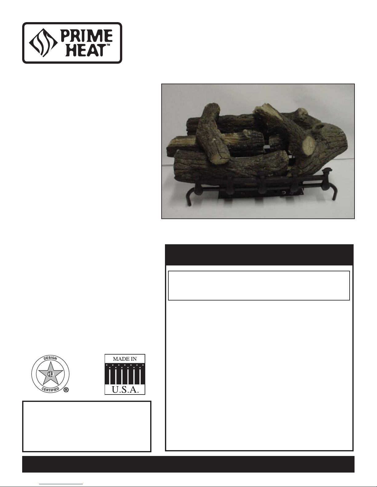
MAKE SURE YOU HAVE RECEIVED ALL PARTS:
Check your packing list to verify that all listed parts have been received. You should have the following:
• Unvented gas log burner assembly • Plastic bag containing crushed volcanic rock
• Installation/operating instructions • Two (2) anchoring screws
• Refractory Cement Logs • Grate
The millivolt controlled version of this heater is the only style designed to be operated with optional devices for ON/OFF
functions. The following options may be used with the millivolt controlled heater. These options are not packaged with
the log set.
• Hand held Remote with receiver • Wall thermostat with 15' wire
• Wall switch with 15' wire • Hand held Thermostat Remote with receiver
• Handle the gas log burner assembly by the frame only. Do not pick the
unit up by the burners or grate (not attached to frame).
CAUTION
Carefully inspect the contents for shipping damage. If any parts are missing or damaged, immediately inform the dealer
from whom you purchased the appliance. Do not attempt to install any part of the appliance unless you have all parts
in good condition.
WHAT YOU WILL NEED FOR INSTALLATION:
You must have the following items available before proceeding with installation:
• External regulator (for propane/LPG and 1/2 lb. natural gas systems only)
• Piping which complies with local codes
• Screwdriver
• Drill with 5/32 bit
• Manual shutoff valve
• Pipe sealant approved for use with propane/LPG (Resistant to sulfur compounds)
• Pipe wrench or appropriate size crescent wrench set
• Tee joint.
• Sediment trap
65D2035 5
PRODUCT FEATURES AND SPECIFICATIONS
NATURAL GAS
Manual Pressure Millivolt Pressure
Regulator Pressure Setting: 4.0" w.c. Regulator Pressure Setting: 3.5" w.c.
Gas Inlet Pressure: Max. 10 1/2" w. c. Pilot Regulator: 3.5" w.c.
Min. 5" w.c. Gas Inlet Pressure: Max. 10 1/2" w. c.
Min. 5" w.c.
Gas Rate
Model Number Control
PH24NM Manual 36,000 19,000
PH24NV Millivolt 36,000 24,000
PH18NM Manual 30,000 18,000
PH18NV Millivolt 30,000 26,000
Max BTU/Hr Min BTU/Hr
PROPANE/LPG
Note: An external regulator is required to reduce supply pressure to a maximum of 13" w.c.
Manual Pressure Millivolt Pressure
Regulator Pressure Setting: 10" w.c. Regulator Pressure Setting: 10" w.c.
Gas Inlet Pressure: Maximum 13" w.c. Gas Inlet Pressure: Maximum 13" w.c.
Minimum 11" w.c. Minimum 11" w.c.
Gas Rate
Model Number Control
PH24PM Manual 36,000 25,000
PH24PV Millivolt 36,000 29,000
PH18PM Manual 30,000 22,500
PH18PV Millivolt 30,000 24,500
IGNITION CONTROLS
Max BTU/Hr Min BTU/Hr
Piezo ignitor allows ignition of the pilot without the use of matches or batteries.
Manual control has three (3) positions:
OFF - All gas to the gas logs is shut off at the valve.
IGN - Valve position to light/maintain a standing pilot.
HI/LOW - Variable position corresponding to desired flame height (heat input)
Millivolt control has four (4) positions:
OFF - All gas to the gas logs is shut off at the valve.
IGN - Valve position to light/maintain a standing pilot.
ON - Valve position to turn ON/OFF log set with remote switch/thermostat.
HI/LOW - Variable position to control flame height (heat output).
PILOT
The gas log heater is fitted with a specially designed safety pilot light (ODS assembly) which senses the amount of oxygen
available in the room and shuts the gas log heater off if the oxygen level begins to drop below a satisfactory level. The pilot
can only be relit when adequate fresh air is available.
THERMAL GENERATOR
The millivolt gas log pilot is fitted with a millivolt generator to provide power for remote activation.
6 65D2035

GENERAL INSTALLATION INFORMATION
CODES
Adhere to all local codes or, in their absence, the latest edition of THE NATIONAL FUEL GAS CODE ANSI Z223.1 or
NFPA54 which can be obtained from . . .
American National Standards Institute, Inc.
1430 Broadway
New York, NY 10018
or
National Fire Protection Association, Inc.
Batterymarch Park
Quincy, MA 02269
ADEQUATE COMBUSTION AND VENTILATION AIR
This heater shall not be installed in a confined space or unusually tight construction unless provisions are provided for
adequate combustion and ventilation air.
The National Fuel Gas Code, (ANSI Z223.1), defines a confined space as a space whose volume is less than 50 cubic feet
per 1,000 BTU per hour (4.8 m
fined space is defined as a space whose volume is not less than 50 cubic feet per 1,000 BTU per hour (4.8 m3 per kw) of the
aggregate input rating of all appliances installed in that space. Rooms communicating directly with the space in which the
appliances are installed, through openings not furnished with doors, are considered a part of the unconfined space.
UNUSUALLY TIGHT CONSTRUCTION IS DEFINED AS CONSTRUCTION WHERE . . .
a) walls and ceilings exposed to the outside atmosphere have a continuous water vapor retarder with a rating of 1 perm
(6 x 10
b) weather striping has been added on openable windows and doors, and
c) caulking or sealant are applied to areas such as joints around windows and door frames; between sole plates and doors;
between wall-ceiling joints; between wall panels; at penetrations for plumbing, electrical, and gas lines; and at other
openings.
11
kg per-pa-sec-m2) or less with openings gasketed or sealed, and
3
per kw) of the aggregate input rating of all appliances installed in that space. An uncon-
65D2035 7
GENERAL INSTALLATION INFORMATION
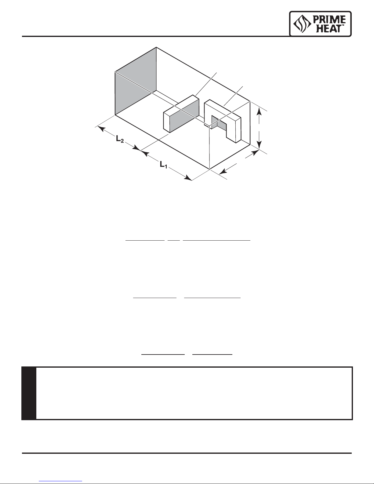
Figure 1 - Example of a Large Room with 1/2 Wall Divider
Counter
Fireplace
H
W
The following formula can be used to determine the maximum heater rating per the definition of unconfined space:
BTU/Hr = (L1 + L2) Ft x (W) Ft x (H) Ft
x 1000
50
Consider two connecting rooms with an open area between, with the following dimensions:
1
1 = 15
L
/2 Ft., L2 = 12 Ft., W = 12 Ft., H = 8 Ft.
BTU/Hr = (151/2 + 12) x (12) x (8)
x 1000 = 52800 BTU/Hr
50
If there were a door between the two rooms the calculation would be based only on the room with the heater.
BTU/Hr = (151/2) x (12) x (8)
x 1000 = 29760 BTU/Hr
50
If the area in which the heater may be operated is smaller than that defi ned as an
unconfi ned space or if the building is of unusually tight construction, provide adequate
combustion and ventilation air by one of the methods described in the National Fuel
Gas Code, ANSI Z223.1, Section 5.3 or applicable local codes.
WARNING
8 65D2035
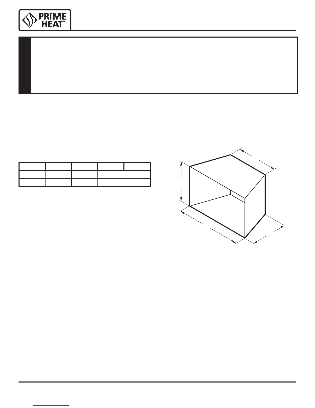
FIREPLACE AND HEARTH DIMENSIONS
This appliance has been specifi cally tested and design certifi ed for installation only
in a solid-fuel burning fi replace including factory-built UL127 fi replaces and masonry
fi replaces, or in a listed ventless fi rebox (see below).
Exception: DO NOT install this appliance in a factory-built fi replace that includes
instructions stating that it has not been tested or should not be used with unvented
WARNING
gas logs.
Use manufacturer’s installation and clearance requirements as defined in their manual.
The PH Series unvented room heater is approved for installation into the following unvented fireplaces:
GCUF(32,36,42) and VFR(32,36,42) Series Fireboxes
The PH Series unvented room heater may also be installed into a Ventless Firebox Enclosure for Gas Fired Decorative
Type Unvented Room Heaters per ANSI Z21.91b.2004, as long as firebox hearth dimensions meet the minimum hearth
dimensions shown below.
C
Model ABCD
PH18 25" 13" 171/2" 17"
PH24 29" 13" 191/2" 17"
D
A
Figure 2 - Hearth Minimum Dimension for Solid Fuel Burning
Fireplaces and UL127 Factory Built Fireplaces
B
65D2035 9
PLACEMENT IN A FIREPLACE WITH A RESTRICTIVE BARRIER
IMPORTANT INFORMATION FOR THE INSTALLATION OF THIS GAS LOG SET
The following are guidelines for placing a gas log set in a fireplace that has a restrictive barrier along the bottom front opening of the fireplace. Some examples of barriers are glass/screen door frames and sunken/recessed fireplaces.
Height of Restriction (X) Minimum Depth of Fireplace/Firebox
No restriction 13"
0 to 1.5" 16"
Greater than 1
Greater than 3" Any barrier greater than three inches (3") placed in front of the gas log set is not
Glass door frames
louvers should have
the lovers fully open
while the unit is in
1
/2" to 3" 16"
with adjustable
operation.
recommended by the manufacturer.
The log set should be
placed against or as near
as possible to the rear wall
of the fireplace/firebox.
Height of restrictive barrier
caused by glass door frames,
recessed fireplaces, etc. from
the base or bottom surface of the
unit. (See Table).
Figure 3 - Reference Drawing of a Natural Flame Log Set in an Enclosure
X
Depth of fireplace/firebox.
(SeeTable).
Barriers such as the bottom of a glass door frame placed in front of a gas log set can
change the air fl ow characteristics of the fi replace which in turn can cause the unit to
overheat and malfunction.
WARNING
NOTE: Non combustible material such as refractory brick may be used to line the fl oor of the fi replace
in order to raise the height of the gas log set in relation to a restrictive barrier. If the unit is raised,
the minimum height dimension listed in the homeowner’s manual must not be exceeded.
NOTE: If the log set is equipped with a remote receiver, a restrictive barrier may reduce the battery
life by increasing the ambient temperature inside the fi replace. Placement of the receiver outside of
the fi replace will extend the battery life.
10 65D2035
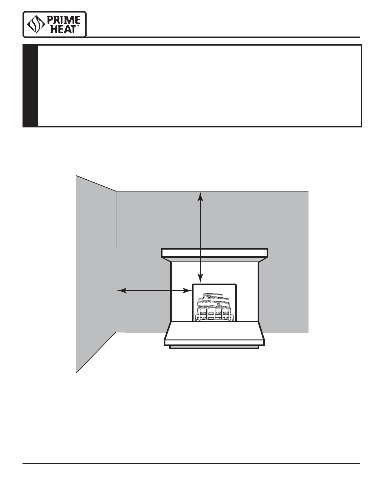
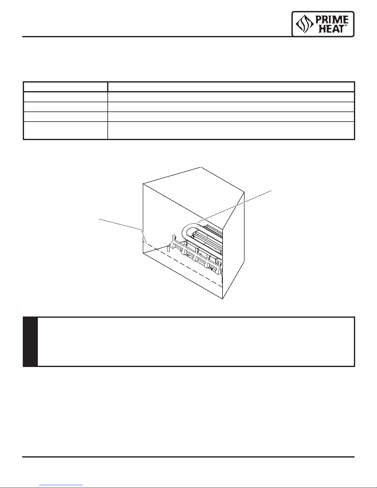
CLEARANCES AND HEIGHT REQUIREMENTS
The dimensions shown in Figures 4 through 10 and defi ned in the fi replace manufacturer's
instructions are minimum clearances to maintain when installing this heater. Left and
right clearances are determined when facing the front of the heater.
When heater is installed into a ventless fi rebox, minimum clearances, as specifi ed by
the ventless fi rebox manufacturer, must be met.
WARNING
Follow these instructions carefully to ensure safe installation. Failure to follow
instructions exactly can create a fi re hazard.
Sidewall and ceiling clearances: The sides of the fireplace opening must be at least 16" from any combustible wall.
The ceiling must be at least 42" from the top of the fireplace opening.
42"
16"
Figure 4 - Sidewall and Ceiling Clearances
65D2035 11
e
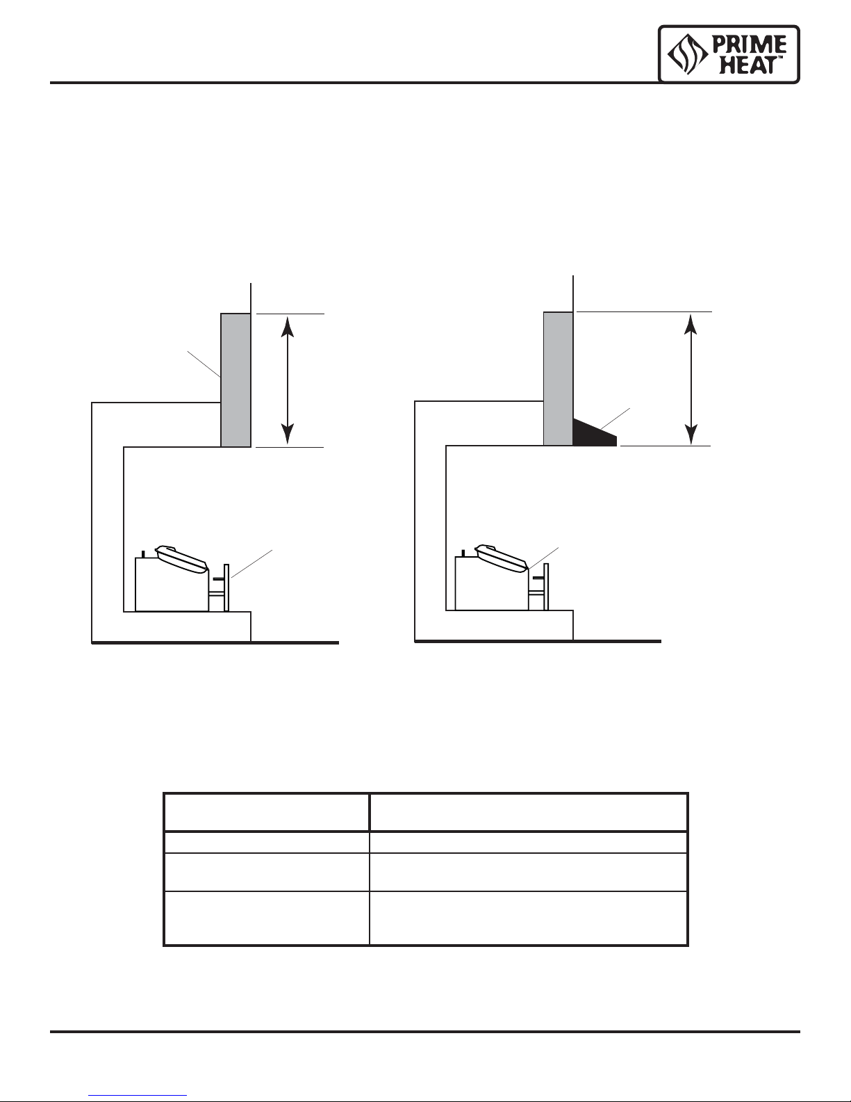
CLEARANCES and HEIGHT REQUIREMENTS
Heat resistant material (minimum requirements) with no wooden mantel or other combustible
projection:
To install the gas logs into a fireplace with no wooden mantel, shelf or other combustible projection above the fireplace
opening, measure the heat resistant material height, per Figure 5, then see TABLE A.
1
Heat resistant materials such as slate and marble must be at least
combustible material.
IMPORTANT: If you cannot meet these minimum clearances you must operate the heater with chimney flue damper open.
See Installing Vented Applications found on page 16.
Heat
Resistant
Material
Measur
this
distance
/2" thick. Sheet metal should not be installed onto
8" or More of
Heat Resistant
Hood
Material
Heater in
Fireplace or
Firebox
Figure 5 - Measuring Heat Resistant Material
Figure 6 - Measuring Heat Resistant Material
Heater in
Fireplace or
Firebox
for Mantel
Heat resistant material (minimum requirements) with wooden mantel or other combustible projection:
To install the heater with a wooden mantel, shelf or other combustible projection above, first measure the heat resistant
material shown in Figure 6, then see TABLE B, page 13.
HEAT RESISTANT MATE-
RIAL MEASUREMENT
20" or more Hood not required.
8" to less than 20" Extend heat resistent material to 20" or install Hood.
Less than 8" Extend heat resistant material to at least 8" and
REQUIREMENTS FOR SAFE INSTALLATION
See Figure 6.
install hood. See Figure 6. OR, extend heat resistant
material to a height of at least 20".
PH24/18
TABLE A - Heat Resistant Material Requirements with No Mantel or Combustible Projection
12 65D2035
 Loading...