


High Definition
Digital TV Tuner
Set Top Box
User Operation Guide
Model: PHD-101
© Copyright 2005, PrimeDTV Technologies, Inc.

Safety Precautions
CAUTION: TO REDUCE THE RISK OF ELECTRIC
SHOCK, DO NOT REMOVE COVER (OR BACK). NO
USER SERVICEABLE PARTS INSIDE. REFER
SERVICEING TO QUALIFIED SERVICE PERSONNEL.
This lighting flash with arrowhead symbol indicates high
voltage is present inside. It is dangerous to make any kind of
contact with any inside part of this product.
This exclamation point symbol alerts you that important
literature concerning operation and maintenance has been
included with this product.
Note to CABLE/TV Installer: This reminder is provided to call cable TV
system installer’s attention to Article 820-40 of the National Electrical Code
(Section 54 of Canadian Electrical Code, Part I), that provides guidelines for
proper grounding and, in particular, specifies that the cable ground shall be
connected to the grounding system of the building as close to the point of
cable entry as practical.
Caution: FCC regulations start that any unauthorized changes or
modifications to this equipment may void the user’s authority to operate it.
Caution: To prevent electric shock, match the wide blade of plug to the wide
slot, and fully insert the plug.
Attention: pour eviter les chocs electriques, introduire la lame le plus large de
la fiche dans la borne correspondante de la prise et pousser jusqu’au fond.
Important: One Federal Court has held that unauthorized recording of
copyrighted TV programs is an infringement of US copyright laws. Certain
Canadian programs may also be copyrighted and any unauthorized recording
in whole or in part may be in violation of these rights.
Warning: To prevent damage which may result in fire or electric shock hazard,
do not expose this appliance to rain or moisture.
- 1 -

Important Safety Instructions
IMPORTANT SAFETY INCTRUCTIONS
CAUTION: PLEASE READ AND OBSERVE ALL WARNINGS AND
INSTRUCTIONS IN THIS INSTALLATION AND OPERATING GUIDE AND
THOSE MARKED ON THE UNIT. RETAIN THIS GUIDE FOR FUTRE
REFERENCE.
This set has been designed and manufactured to assure personal safety.
Improper use can result in electric shock or fire hazard. The safeguards
incorporated in this unit will protect you if you observe the following procedure
for installation, use and servicing.
This unit does not contain any parts that can be repaired by the user.
1. Read these instructions – All these safety and operating instructions
should be read before the product is operated.
2. Keep these instructions - The safety, operating and use instructions
should be retained for future reference.
3. Heed all warnings – All warnings on the product and in the operating
instructions should be adhered to.
4. Follow all instructions – All operating and use instructions should be
followed.
5. Do not use this apparatus near water – For example: near a bath
tub, wash bowl, kitchen sink, laundry tub, in a wet basement, near a
swimming pool, etc.
6. Clean only with dry cloth – Unplug this product from the wall outlet
before cleaning. Do not use liquid cleaners.
7. Do not block and ventilation openings. Install in accordance with
the manufacturer’s instructions – Slots and openings in the cabinet
are provided for ventilation, to ensure reliable operation of the product,
and to protect it from over-heating. The openings should never be
blocked by placing the product on a bed, sofa, rug or other similar
surface. This product should not be placed in a built-in installation
such as a bookcase or rack unless proper ventilation is provided and
the manufacturer’s instructions have been adhered to.
- 2 -

Important Safety Instructions
8. Do not install near any heat sources such as radiators, heat
registers, stoves, or other apparatus (including amplifiers) that
produce heat.
9. Do not defeat the safety purpose of the polarized or groundingtype plug. A polarized plug has two blades with one wider than
the other. A grounding type plug has two blades and a third
grounding prong. The wide blade or the third prong is providing
for your safety. If the provided plug does not fit into your outlet,
consult an electrician for replacement of the obsolete outlet.
10. Protect the power cord from being walked on or pinched
particularly at plugs, convenience receptacles, and the point
where they exit from the apparatus.
11. Only use attachments/accessories specified by the manufacturer.
12. Use only the cart stand tripod, bracket, or table specified by the
manufacturer, or sold with apparatus. When a cart is used, use
caution when moving the cart/apparatus combination to avoid
injury from tip-over.
13. Unplug this apparatus during lighting storms or when unused for
long periods of time.
14. Refer all servicing to qualified service personnel. Servicing is
required when the apparatus has been damaged in any way,
such as power supply cord or plug is damaged, liquid has been
spilled or objects has fallen into the apparatus, the apparatus has
been exposed to rain or moisture, does not operate normally, or
has been dropped.
- 3 -

Table of Contents
CONTENTS
Safety Precautions ………………………………………................ 1
Important Safety Instructions ……………………………………… 2
Introduction …………………………………………………………. 6
PHD-101 Components …………………………………………….. 7
Front Panel ………………………………………………………….. 8
Rear Panel …………………………………………………………… 9
Remote Control ……………………………………………………… 11
Installing Batteries ………………………………………………….. 12
Connecting PHD-101 ………………………………………………. 14
Antenna / RF Connections ………………………………………… 14
Connecting PHD-101 to TV Set …………………………………… 15
Connecting to Digital Ready TV …………………………………… 15
Connecting to Conventional Analog TV ………………………….. 16
- 4 -

Table of Contents
CONTENTS
- 5 -

Introduction
PrimeDTV proudly presents the latest design, high performance and cost
competitive high-end HDTV Tuner receiver Set-Top Box, PHD-101. This unit
can receive ATSC over-the-air HDTV digital broadcast signals as well as
digital
Cable clear QAM (64 and 256 QAM signals) from an external antenna/
cable RF source.
PHD-101 is a perfect match for consumer's EDTV or HDTV monitors, or
converts HDTV signals to analog signals for conventional TV displaying. The
unit features Component (YPbPr HD/SD), RGB, DVI, S-Video and Composite
(CVBS) video outputs. Audio outputs include Dolby® Digital Optical and
Stereo L/R sound.
The PHD-101 offers:
• Receiving and decoding all over-the-air (ATSC) HDTV/SDTV formats
• Receiving and decoding Digital Cable (Clear QAM ) HDTV/SDTV
formats
• HD Component (Y-Pb-Pr), RGB, Composite and S-Video Outputs,
and DVI HDTV output
• Rear-panel switch for selecting output (1080i / 720p / 480p / 480i)
• V-CHIP & Closed Captioning from ATSC and NTSC Source
• Electronic Programming Guide (EPG) for TV program review
• Channel list and Channel Enable / Disable features
• Video Output format selectable for 16:9 and 4:3 aspe ct ratio
• Letterbox, Zoom, and Full output modes for viewing 16:9 programs on
4:3 TV and Monitors
• Powered by ATI XILLEON 300 MHz MIPS® Processor with powerful
display graphic engine
- 6 -

Introduction
PHD-101 Components
The following items are packed with your PHD-101
• Remote control with 2x AAA batteries
• Audio / Video cables (Yellow-Red-White cables)
• Component cables (Green-Blue-Red cables)
• PHD-101 User Operation Guide
You’ll also need the following items to get started:
• An Indoor or Outdoor TV Antenna
• Or Digital Cable signal
• A coaxial cable to attach the antenna or connect digital cabl e to RF
input of your PHD-101 unit.
- 7 -

Front Panel
Power ON/OFF button
1
Switch to turn PHD-101 on or off.
UP button
2
Part of On-Screen (OSD) Menu control. Navigating OSD button up.
DOWN button
3
Part of OSD Menu control. Navigating OSD button down.
LEFT button
4
Part of OSD Menu control. Navigating OSD button left.
RIGHT button
5
Part of OSD Menu control. Navigating OSD button right.
ENTER button
6
Part of OSD Menu control. Enter to select more menu functions.
MENU button
7
Bring up OSD Menu.
CLEAR button
8
Exit menu or clear current menu selection.
Power LED
9
Lights to indicate PHD-101 on or standby state.
- 8 -

Rear Panel
AIR/CABLE IN
1
Connect Over-the-Air antenna or Digital Cable signal here. The Digital cable
signal is only clear QAM signal, which local cable provider is passing through
8VSB on their system.
VIDEO OUT
2
Connect this jack to your conventional TV or VCR having composite video input.
DTV OUT (Component, Y-Pb-Pr format)
3
Connect these jacks to your TV digital component inputs. These jacks can
support HD or SD with different video resolutions (480p, 720p, 1080i) settings.
ANALOG AUDIO L/R OUT
4
Connect these jacks to your analog audio inputs of your TV or Stereo system.
S-VIDEO OUT
5
Connect to your analog conventional TV S-Video input with better video quality.
DTV OUT (RGB format)
6
Connect this 15-pin VGA type connector to your TV digital RGB inputs. This jack
can support HD or SD with different video resolutions (480p, 720p, 1080i)
settings.
DOLBY DIGITAL OUT (Optical)
7
Use this jack to connect digital audio to your TV or audio system.
DIGITAL DVI OUT
8
Use this to connect other DVI interface equipment. This jack can support HD or
SD with only 480p and 720p settings.
USB OUT
9
USB Host connector for special service upgrade. Not for general use.
- 9 -

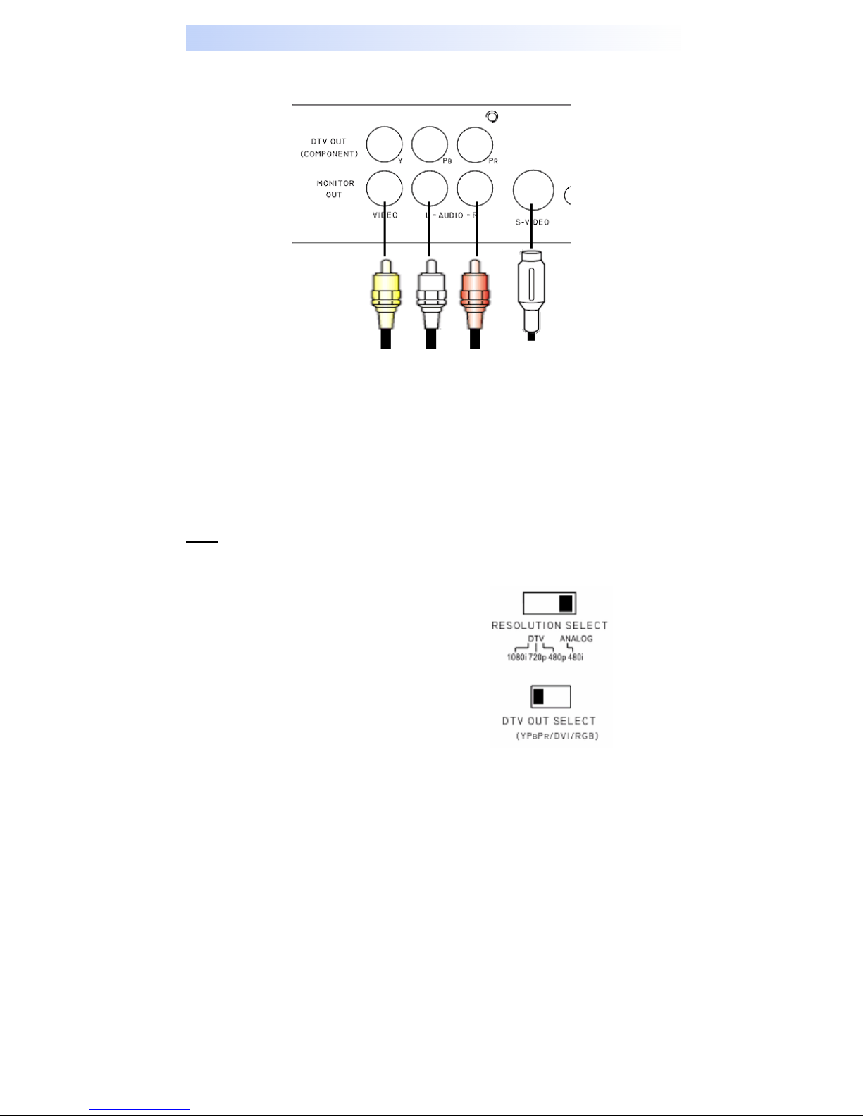
Rear Panel
DTV OUT SELECT
10
A switch to select different DTV output signal, which can be either Y-Pb-Pr,
RGB or DVI to your TV.
RESOLUTION SELECT
11
Switches between different resolution formats. The “i” stands for interlaced
scanning. The “p” stands for progressive scanning.
• 1080i
Use this setting for HDTV Ready TV monitor, which can handle 1080i
video output format.
• 720p
Use this setting for HDTV Ready TV monitor, which can handle 720p
video output format.
• 480p
Use this setting for Digital Ready TV monitor including EDTV and
HDTV that can support 480p video output format.
• 480i
Use this setting for a conventional TV with composite video (CVBS) or
S-Video inputs.
AC POWER IN
12
A wire to connect to AC power outlet to power PHD-101 unit.
- 10 -
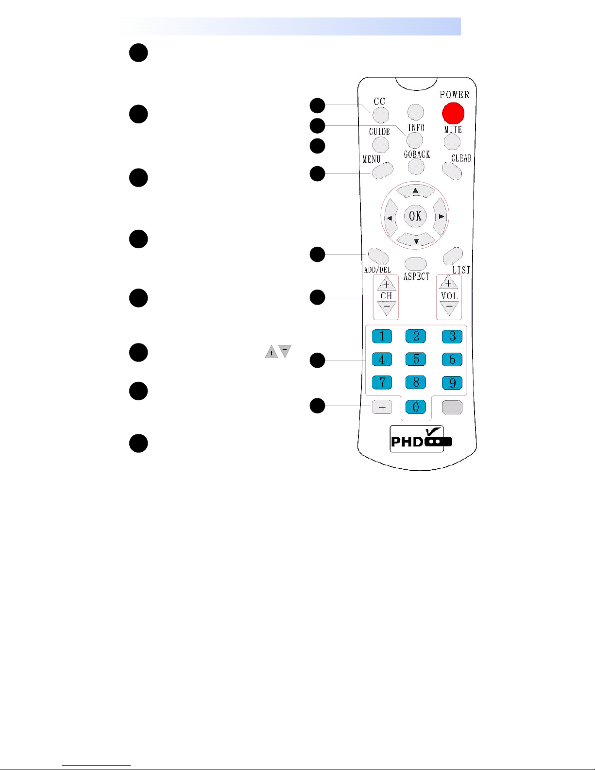
Remote Control
1
CC (Close Caption)
Press to enable digital and analog
close caption when signal is
available from TV stations.
2
INFO (Program Information)
Press to display current TV program
and channel detail information on the
screen. Press again to turn off.
GUIDE
3
Press to show current channel's EPG
(Electronic Program Guide) for 12
hours period of time.
MENU
4
Press to bring up OSD (On-ScreenDisplay) Menu to set up PHD-101
functions.
5
ADD/DEL
Press to add and delete current
scanned channels.
Channel (Up/Down)
6
Press these keys to change channels.
7
Channel Number Buttons
Press to directly tune to a specific
channel.
8
Sub-Channel (-) Button
Press this key after channel number
and followed by sub channel number
to tune a specific a sub channel. For
ex. “07-2” meaning channel 7.2.
1
2
3
4
5
6
7
8
- 11 -
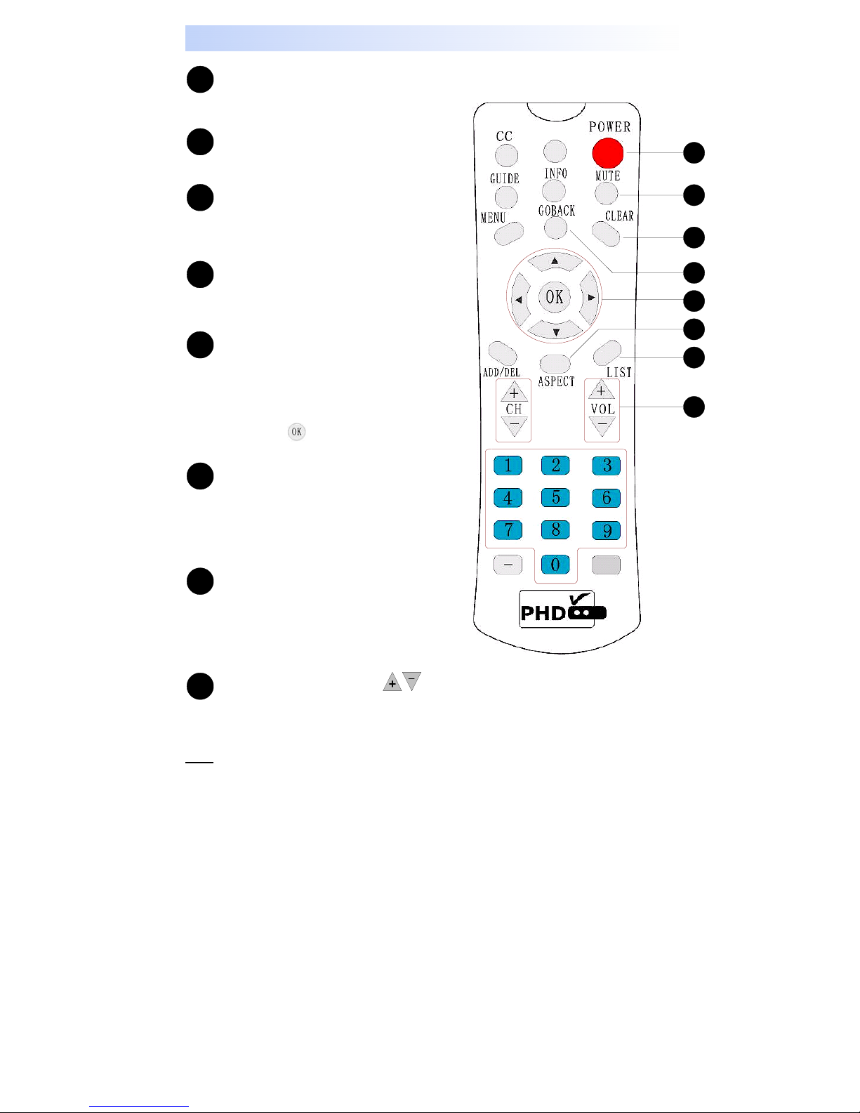
Remote Control
POWER
9
Press to turn PHD-101 power on or off.
MUTE
10
Mute TV audio. Press again to un-mute.
11
CLEAR
Clear current OSD display or exit the
menus.
GOBACK
12
Press to return the previous select
channel.
13
Navigation Buttons
Use Navigation buttons
(Up/Down/Left/Right) to move and
select OSD Menu functions or select
channel listing as well as ADD/DEL
channels. OK button is to enter
and confirm current OSD Menu settings.
14
ASPECT
Press to change display aspect ratio
based on selected TV resolution. Keep
pressing this key to cycle through all
aspect ratio modes.
15
LIST
Press to display all scanned DTV
channels. Use Navigation keys to
cruise the desired channel and press
OK to tune to that channel.
Volume Control
16
Adjust volume by pressing the VOL
(+/-) keys.
: Two unlabeled keys are unused and no functions associated with.
Note
- 12 -
9
10
11
12
13
14
15
16

Remote Control
Installing Batteries
Press and remove the battery cover on the back of remote control.
Put 2 x AAA batteries into the compartment and put the battery cover back.
- 13 -

Connecting PHD-101
Antenna / RF Connections
1 Connect an Indoor or Outdoor Antenna directly to this jack with a coaxial
RF cable. This is to receive Over-the-Air (OTA) Digital TV signals from TV
broadcasters.
Note: OTA DTV signal is 8VSB signal, which is RF modulation format utilized
by ATSC.
2 Connect to Cable signal source using a coaxial RF cable.
Note: The PHD-101 can receive DTV signal in the event that a local cable
provider is passing 8VSB through their system. This 8VSB signal can not be
encrypted by Cable Company. And we call it Clear QAM signal from cable.
- 14 -

Connecting PHD-101 to TV Set
Connecting to Digital Ready TV
Digital Ready TV is a TV monitor, which can accept and display progressive video and
higher resolutions video format on the screen. Digital Ready TV is typically including
Plasma Display Panel (PDP) TV, Liquid Crystal Display (LCD) TV, DLP (Digital Light
Processor) TV and High-end progressive Projection/CRT TV or Projector
.
1 Connect antenna cable to AIR/CABLE jack of PHD-101 unit. Refer to
previous section “Antenna /RF Connections”.
2 Connect video component cable (Y-Pb-Pr cable) from DTV OUT (Component)
jack of PHD-101 to your digital ready TV component video connector input s.
3 Or, you can connect RGB video from DTV OUT (RGB) jack to your digital ready
TV or RGB video monitor (for ex. like PC monitor).
4 If your digital ready TV equips the digital DVI input, you can connect DVI cable
from DVI OUT jack to your digital ready TV.
5 Connect an audio cable from DOLBY
DIGITAL OUT (OPTICAL) to any digital
ready TV or audio system equipping Dolby
digital audio optical input.
6 Or, connect an audio cable from L-AUDIO-R
jacks to digital ready TV L/R audio inputs.
set DTV OUT SELECT switch to proper position for correct video format output.
Note:
- 15 -
Connecting PHD-101 to TV Set
Connecting to Conventional Analog TV
1 Connect antenna cable to AIR/CABLE jack of PHD-101 unit. Refer to
previous section “Antenna /RF Connections”.
2 Connect video cable from MONITOR OUT VIDEO jack to the TV video (CVBS)
input.
3 Or, connect S-Video cable from S-VIDEO jack to TV S-video input for a better
video displaying.
4 Connect audio cable from MONITOR OUT L-AUDIO-R jacks to the TV stereo
(L/R) audio inputs.
Note:
Connecting conventional video signal to analog TV, you need to set “RESOLUTION
SELECT” switch to 480i position to ensure the output video format matches the
conventional TV signal. And set DTV OUT SELECT switch to Y-Pb-Pr position.
- 16 -

MENU Operation
- 17 -
 Loading...