

Page 1
OPERATING INSTRUCTIONS
SNGL
COM
COM
COM
COM
+24V
+24V
CAL1+
NOTAB
CAL2+
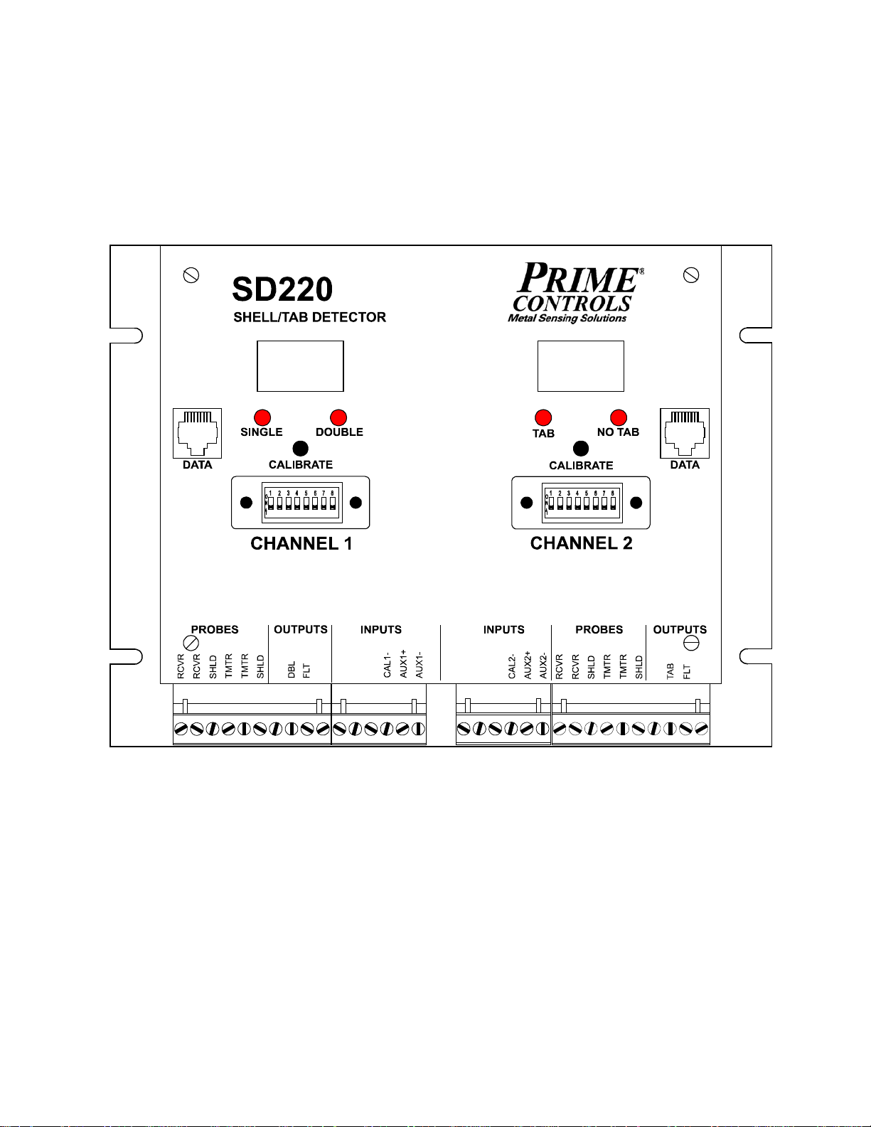
MODEL SD220 SHELL/TAB DETECTOR
DESCRIPTION
The Model SD220 Shell Detector for conversion press applications is a rugged but
sensitive dual channel instrument designed specifically to detect and report missing
blanks or double blanks at the infeed to a conversion press and to detect and report
ends that exit the press without tabs.
A complete system for one lane of a press comprises a control module housed in an
aluminum enclosure and four probes. One transmitting and receiving probe pair
senses doubles at the press input while the second transmitting and receiving pair
senses the presence or absence of tabs at the press output.
March 13, 2019
Page 2

2
TABLE OF CONTENTS
DESCRIPTION Control Module………………………………………………….………... Page 3 Calibrate Pushbutton Operation………………………………………... Page 3 Probes………………………………………………………………….…. Page 4
OPERATION Calibration …………………………………………………………….….. Page 4 Fault Message Interpretation ……………………………………….….. Page 5
INSTALLATION Installing the Probes ……………………………………………….….… Page 5
Mounting the Control Module ………………………….………….…….Page 6
Wiring the Contro l Mod ule ………………………………………..……..Page 6
Setting Switch Options ………………………………………….………. Page 7
Sensing Aluminum Ends ……………………………………….. Page 8 Sensing Steel Shells ……………………………………………. Page 8 Sensing Al Tabs on Al Ends ……………………………….……Page 8 Sensing Al Tabs on Steel Ends ………………………………. . . Page 8 Sensing Steel Tabs on Stee l Ends ………………………….… Page 8 Set Sinking or Sourcing Outputs ………………………………. Page 8 Set Outputs for Failsafe or Compatibility …………………….. Page 8 Enable or Disable Tab Profiling ………………………………...Page 9
Setting Options Through the Front Panel…………………………..…. Page 9 Adjusting the Tolerance……………………………………….… Page 9 Set Display Direction………………………………………….…. Page 10 Parameter Value Ranges……………………………………….. Page 11
Special Functions………………………………………………………… Page 11 Remote Calibration…………………………………………….… Page 11 Quick Calibration Changeover………………………………….. Page 11 Determining Firmware Version…………………………………. Page 12
DOCUMENT APPLICABILITY…………………………………………….……. Page 12
ELECTRICAL SPECIFICATIONS……………………………………………… Page 13
CONTROL MODULE DIMENSIONS…………………………………………... Page 14
WIRING RECOMMENDATI O NS………………………………………………. . Page 15
OUTPUT SIGNAL DIAGRAMS………………………………………………….Page 16
SUMMARY OF DIFFERNCES BETWEEN SD200 AND SD220…………… Page 17
SD200 TO SD220 MIGRATION…………………………………………………Pa ge 1 8
LIMITATION AND EXCLUSION OF WARRANTIES………………………….Page 19
Page 3

3
Control Module
The control module allows for fast and easy setup and for quick diagnosis of system
errors or problems. Setup is achieved through the simple press of a push-button switch
or an external contact closure. Faults are reported on digital displays on the control
module and through FAULT outputs that may be connected to a PLC or system
controller.
The DOUBLE, SINGLE, NO TAB, TAB and FLT outputs may be switch selected as
sinking or sourcing drivers. An eight position DIP switch, accessible on the front panel,
allows the installer to select a number of operational options as described in the
installation section of this document.
The AUX inputs provide a means to switch between two different setups, such as
sensing steel shells and sensing aluminum shells, without recalibrating or changing the
DIP switch settings.
When the unit first powers up, if probes are properly connected, the digital displays
indicate the operational mode of the unit, i.e. whether set up for sensing Aluminum,
Steel, or Aluminum on Steel by displaying the characters "Al", "St" or “AS” for a period
of approximately two seconds. Which mode comes up is determined by the setup of
the unit through the DIP switches and the state of the AUX input. See setup later in this
document.
Calibrate Pushbutton Operation The push-button switches on the front panel of the control module serve to initiate the
calibration process and to make adjustments for system setup. The pushbuttons may
be used to adjust the gauge tolerances (tL) and set the display option to invert the
digital display (do).
To initiate calibration, simply press the appropriate pushbutton and release it within 3 seconds.
To view the current value of a parameter, press the pushbutton and hold it for more
than 3 seconds until the appropriate parameter identifier (tL or do) appears on the
digital display. After the parameter identifier appears, release the pushbutton and the
current value of the parameter displays for 5 seconds. To retain the current value of
the parameter, simply allow the 5 second display interval to elapse. The display
reverts to displaying the gauge signal.
To change the value of a parameter, press the pushbutton and hold it for more than 3
seconds until the appropriate parameter identifier appears on the digital display. After
the parameter identifier appears, release the pushbutton and the current value of the
parameter displays. Press the pushbutton while the parameter is displaying and the
value increments, first slowly then more rapidly. For more precise control of the value
adjustment, simply tap the pushbutton repeatedly until the desired value is displayed.
All parameters roll back to their minimum values after reaching the maximum value.
To retain the adjusted value of the parameter, simply allow the 5 second display
interval to elapse. The display reverts to displaying signal strength.
Page 4

4
Probes
The SD220 may be used with any P15 or P70 series two wire probes or with older
model three wire probes including AV, AY, AZ, AZA, and CB probes. When used with
older 3 wire probes, the white wire in the probe cable is not used and must remain
disconnected.
OPERATION Operation of the SD220 Shell/Tab Detector involves only two processes, calibration and
fault message interpretation. These processes are described below.
Calibration Calibration requires the following steps:
1. Stop the press in the dwell portion of the cycle with a single end between the
infeed probes and a good tabbed end between the discharge probes.
2. Observe that no error conditions are being reported on either display of the
SD220 control module.
3. Press and release the CALIBRATE pushbutton on channel 1 of the SD220
control module and observe the SINGLE and DOUBLE LEDs flashing alternately
and “CAL” on the digital display. If the calibration is successful, the LED flashing
stops in less than three seconds and the digital display shows a number between
48 and 52.
If the display flashes alternately “CAL” and “Lo”, the calibration was
unsuccessful due to insufficient signal at the receiving probe. This can be an
indication that the probes are too far apart or that the unit is not set to the
appropriate frequency for the material being sensed, e.g. frequency set to
aluminum when steel ends are present. If the display flashes alternately “CAL”
and “Hi”, the receiver signal is too strong indicating nothing between the probes.
If the calibration problem is not resolved and the calibration switch is not pressed
again within 30 seconds, calibration mode is aborted and the previous calibration
values are reinstated.
4. Press the CALIBRATE pushbutton on channel 2 of the SD220 control module
and observe the TAB and NO TAB LEDs flashing alternately and ”CAL” on the
digital display. If the calibration is successful, the LED flashing stops in less than
3 seconds and a number between 28 and 33 is displayed.
If the display begins to alternately flash “CAL” and “Lo”, the calibration was
unsuccessful due to insufficient signal at the receiving probe. This can be an
indication that the probes are too far apart or that the unit is not set to the
appropriate frequency for the material being sensed e.g. frequency set to
aluminum when steel ends are present.
Page 5

5
If the calibration problem is not resolved and the calibration switch pressed again
within 30 seconds, calibration mode is aborted and the previous calibration
values are reinstated.
If both channels calibrate successfully, calibration is complete. The calibration process
may also be initiated through an external switch or signal controlling the CAL+ and
CAL- inputs to the SD220. Activation of this input performs the same function as
pressing the CALIBRATE push-button switch for the corresponding channel.
Fault Message Interpretation
The SD220 monitors the probe connections on a continuous basis and reports what it
detects to be disconnected or malfunctioning probes. The probe faults are reported as
follows:
Alternately flashing "PR" and "1" - transmitter probe disconnected or failing.
Alternately flashing "PR" and "2" - receiver probe disconnected or failing.
Alternately flashing "PR" and "3" - both probes disconnected or failing
During calibration:
Alternately flashing “CAL” and “Lo” indicates a low signal at the receiving probe.
Alternately flashing “CAL” and “Hi” indicates the signal at the receiver is too
strong, likely no end between the probes.
The SD220 performs extensive self diagnostics at power up and more limited
diagnostics while running. Most fatal faults, if not involving the display subsystem, are
reported on the digital displays through the alternate flashing of "Err" and "nnn" where
"nnn" is a one to three digit number indicating the source of the fault. These faults are
not field repairable and require the change-out of the control module.
Any detected fault causes the FLT output to be turned OFF until the fault is cleared.
INSTALLATION
Installation comprises four basic steps: 1) Installing the probes, 2) Mounting the
control module, 3) Wiring the unit, and 4) Setting system options. Each of these steps
is further expanded below.
Installing the Probes
1. Mount the double detecting infeed probes, one above and one below the
centerline of the track carrying the ends into the press. The probes must be
positioned such that they are centered on the can end during the dwell portion of
the press cycle. In the vertical, the track should run midway through a gap of
approximately 5/8 inch (16mm) between the probes.
Page 6

6
2. Positioning of the tab detecting probes is more critical than the positioning of the
infeed probes. For most tabbed ends, the optimum position for the probes is
above and below the ring of the tab, not centered on the rivet. Centering on the
rivet only works on some older tab designs where the tab formed a ring around
the rivet. If positioning of the tab sensing probes is uncertain, contact Prime
Controls for help.
Mount the tab detecting probes, one above and one below the tabbed ends as
they are carried on the track from the press. The probes must be positioned
such that they are centered on the tab ring during the dwell portion of the press
cycle. In the vertical, the track should run midway through a gap of
approximately 5/8 inch (16mm) between the probes.
3. Run the probe cabling through conduit back to the cabinet housing the control
module. Do not run the sensor cables through conduit carrying high level or
noisy signals.
Mounting the Control Module Mount the control module on the back panel of an industrial enclosure. The footprint is
8.25 inches (210 mm) by 6.25 inches (159 mm) with mounting slot locations on a
rectangle 7.625 inches (194 mm) in the horizontal and 4.0 inches (102 mm) in the
vertical. Insure that the mounting screws make good electrical contact between the
module housing and the control enclosure back panel. See drawing at the end of this
document.
Wiring the Control Module
1. Connect 24 volt dc power between both sets of the +24V and COM terminals of
the control module. The left and right side modules are electrically independent
and must be powered independently. The two +24V terminals are NOT
internally connected. The supply must be capable of delivering 0.250 amps
continuously with a startup surge of 0.5 amps for 2 milliseconds.
2. Connect the double detecting transmitter probe wires to the two TMTR terminals
on the channel 1 side of the control module and the double detecting receiving
probe wires to the two RCVR terminals on the channel 1 side of the control
module. The probe connections are not polarized Connect the shield wires to
the terminal labeled SHLD.
Though both the transmitting and receiving probes are identical, it is preferred
practice to choose the transmitting probe as the one that will remain farthest
from the track as it moves and stretches.
Note: Prime Controls assures compatibility with PN: CBL101-XX cables and the
cabling pre-attached to certain probes. Other types of cabling, and also, cable
lengths above 30 meters (approx 100 ft) are not advised.
On retrofit installations where older three wire probes are installed, cut back and
do not connect the third (white) wire. If in doubt about which wires to use,
measure the resistance between the wires in pairs, and then use the pair that
produces the highest resistance reading (typically 24 ohms).
Page 7

7
3. Connect the tab detecting transmitter probe wires to the TMTR terminals on the
channel 2 side of the control module and the tab detecting receiving probe wires
to the two RCVR terminals on the channel 2 side of the control module. Connect
the shield wires to the terminals labeled SHLD.
The precautions regarding choice of transmitter probe are the same for the
discharge side as for the infeed. See above.
4. Connect the SNGL, DBL, NO TAB, TAB, and FLT outputs to the system
controller and/or interlocking circuitry as required. These outputs may be sinking
or sourcing as determined by the setting of SW 5. See switch settings later in
this document.
The FLT outputs are always ON for no fault. The active states of the other
outputs may be affected by the setting of the compatibility DIP switch as
described later in this document.
5. If calibration is to be activated remotely, connect the CAL+ and CAL- inputs
appropriately. Connect a sinking driver or contact to the CAL- terminal and
connect CAL+ to the 24 volt power source. Connect a sourcing driver to the
CAL+ terminal and connect CAL- to COM.
6. If the application may involve switching between steel and aluminum blanks, the
AUX inputs may be wired to provide external control of the sensing mode of the
SD220. Connect a sinking driver or contact to the AUX- terminal and connect
the AUX+ terminal to the 24 volt supply. Connect a sourcing driver to the AUX+
terminal and connect the AUX- terminal to COM.
Setting Switch Options To access the DIP switches in the middle of the front panel, swing the hinged plastic
window to the side. The left-most switch is SW1, the right-most is SW8. The switches are
on when in the up position.
Channel 1 Switch Options
Switch OFF ON
======================================================
SW1 Sense aluminum ends Sense steel ends
SW2 On-press sensing Off-press sensing (high speed)
SW3 Select fail-safe mode Select compatibility mode
SW4 Fixed thresholds Adjustable thresholds
SW5 Sourcing outputs Sinking outputs
SW6 No overlap allowed Overlap allowed if SW2 ON
SW7 Not used
SW8 Not used
Page 8

8
Channel 2 Switch Options
Switch OFF ON
======================================================
SW1 Sense aluminum ends Sense steel ends
SW2 Sense aluminum tabs Sense steel tabs
SW3 Select fail-safe mode Select compatibility mode
SW4 Fixed thresholds Adjustable thresholds
SW5 Sourcing outputs Sinking outputs
SW6 Enable tab profiling Disable tab profiling
SW7 Not used
SW8 Not used
NOTE: The DIP switches are read only upon power-up of the unit. After changing
switch setting, power the unit down and back up again to activate the change.
Sensing Aluminum Ends
When sensing aluminum shells, insure that SW1 is off for both channels.
Sensing Steel Ends
When sensing steel shells, insure that SW1 is on for both channels.
Sensing Aluminum Tabs on Aluminum Ends
When sensing aluminum tabs on aluminum ends, insure SW1 and SW2 are off for both
channels.
Sensing Aluminum Tabs on Steel Ends
When sensing aluminum tabs on steel ends, set SW1 on and SW2 off for channel 1.
Set SW1 on and SW2 off for channel 2.
Sensing Steel Tabs on Steel Ends
When sensing steel tabs on steel ends, set SW1 on and SW2 off for channel 1 and set
both SW1 and SW2 on for channel 2.
Set Sinking or Sourcing Outputs
The setting of SW5 determines whether the output drivers are sinking or sourcing.
SW5 off selects sourcing, SW5 on selects sinking.
Page 9

9
Set Outputs for Failsafe or Compatibility
When SW3 is on, the sourcing outputs of the SD220 provide the same logic levels as
the outputs of older double sheet units such as the DS33 and DS35, allowing for quick
and easy retrofit installations. When SW3 is off, the output states are defined to
provide maximum protection against loss of connection between the shell detector and
the controlling PLC. The loss of connection is sensed as the fault condition.
The table below defines the output states for all combinations of SW3 and the possible
sensing states. Also, see the output signal drawings at the end of this document.
OUTPUT STATES
Switch In Gap SNGL DBL NOTAB TAB
===================================================================
OFF missing OFF ON ON OFF
OFF single ON ON OFF OFF
OFF double/tab ON OFF ON ON
ON missing ON OFF ON OFF
ON single OFF OFF OFF OFF
ON double/tab OFF ON ON ON
Enable or Disable Tab Profiling
The SD220 uses two different methods for determining the absence or presence of
tabs. The most basic method is simple thresholding of the sensor signals. As the
shape of the beverage ends and tabs evolved and the speed of presses increased, it
became necessary to implement a redundant test that recognizes the profile of a tab
as it moves through the machine. This feature, however, is not compatible with larger
and steel ends or with machines that have stainless steel belts. The stainless steel
belts can change the sensor signal sufficiently to interfere with the tab profiling
algorithm and cause the system to report self check errors. Profiling is most effective
in the detection of aluminum tabs on aluminum ends on high speed presses. SW6
enables and disables tab profiling.
Setting Options Through the Front Panel
Adjusting the Tolerance
Adjust the double shell tolerance as follows:
1) Insure that SW4 is on. If necessary, change the switch position and power the unit
down and back up..
2) Press and hold the channel 1 calibrate pushbutton for at least 3 seconds until tL
appears on the display.
Page 10

10
3) Release the pushbutton and observe the current value of the threshold (in percent).
4) If the current value is ok (typically 35), wait 5 seconds and the display reverts to
displaying the gauge value and retains the current tolerance.
5) To change the value, press and hold or tap the calibration pushbutton until the
desired value is displayed. After the value reaches 90, it rolls over to 10 and
increases.
6) When the desired value is on the display, wait 5 seconds and the display reverts to
displaying the gauge value and retains the last displayed tolerance value.
Adjust the missing tab tolerance as follows:
1) Insure that SW4 is on. If necessary, change the switch position and power the unit
down and back up.
2) Press and hold the channel 2 calibrate pushbutton for at least 3 seconds until tL
appears on the display.
3) Release the pushbutton and observe the current value of the threshold (in percent).
4) If the current value is ok (typically 15), wait 5 seconds and the display reverts to
displaying the gauge value and retains the current tolerance.
5) To change the value, press and hold or tap the calibration pushbutton until the
desired value is displayed. After the value reaches 90, it rolls over to 10 and
increases.
6) When the desired value is on the display, wait 5 seconds and the display reverts to
displaying the gauge value and retains the last displayed tolerance value.
Set Display Direction
By default, the digital display values follow the strength of the receiver signal, increasing
for stronger signal and decreasing for weaker signal. In this mode, the signal increases
for thinner materials between the probes and decreases for thicker materials. The
display may be inverted so that the values are proportional to material thickness rather
than signal strength. To invert the display:
1) Press and hold the calibrate pushbutton until do appears on the display.
2) Release the pushbutton and the display changes to 0 or 1.
3) At this point, with each press of the pushbutton the display toggles between 0 and
1. The 0 selects normal display mode, 1 selects inverted mode..
4) When the desired value is on the display, wait 5 seconds and the display reverts to
displaying the signal value in the selected mode.
The range of values available for the SD220 adjustable parameters are as follows:
Page 11

11
Parameter Value Ranges
ID Function Range of Values___________________________
tL double tolerance 10% to 90% for double (default is 35%)
tL tab tolerance 10% to 90% for tab (default is 15%)
do display direction 0 for signal strength (default), 1 relative thickness
oL overlap percentage 0% to 90% for off-press sensing only (SW2 On)
Special Functions
The SD220 offers two sets of optically isolated inputs on each channel that provide
added control over the unit. These are the remote calibration input terminals labeled
CAL+ and CAL- and the sensing mode inputs labeled AUX+, AUX-.
.
Remote Calibration
The remote calibration inputs perform the same function as the CALIBRATE pushbutton switches on the front panel of the control module.
Quick Calibration Changeover
The AUX input works in conjunction with SW1 (both channels) and SW2 (channel 2
only) to select the target tab and shell material combinations as presented in the table
below.
When the AUX input is activated or deactivated, the SD220 changes to accommodate
the new material combination and displays, for approximately 2 seconds, a twocharacter abbreviation indicating the selected targeted materials. The display
interpretation is as follows:
Al – aluminum tab on aluminum shell
St – steel tab on steel shell
AS- aluminum tab on steel shell
The two-character indication also displays at power-up indicating the current selection.
Page 12

12
Channel 1 Material Selection
SW1 AUX Shell Material
OFF OFF Aluminum
OFF ON Steel
ON OFF Steel
ON ON Aluminum
Channel 2 Material Selection
SW1 SW2 AUX Material Combination
OFF OFF OFF Aluminum tab on aluminum end
OFF OFF ON Aluminum tab on steel end
OFF ON OFF Aluminum tab on aluminum end
OFF ON ON Steel tab on steel end
ON OFF OFF Aluminum tab on steel end
ON OFF ON Aluminum tab on aluminum end
ON ON OFF Steel tab on steel end
ON ON ON Aluminum tab on aluminum end
If quick calibration changeover is to be activated remotely, connect the AUX+ and AUX-
inputs appropriately. Connect sinking drivers or contacts to the AUX- terminal and
connect AUX+ to the 24 volt power source. Connect sourcing drivers to the AUX+
terminal and connect AUX- to COM.
Determining Firmware Version
From time to time, as improvements are made to Prime Controls products, the firmware
controlling the units is revised. When setting a unit up or troubleshooting it may be
necessary to determine the version number for the firmware installed in your unit. The
version numbers are of the form 1.00 and are incremented either by tenths (1.01, 1.02,
etc.) for small revisions or by the integer digit (1.00, 2.00, etc.) for more significant
revisions.
To determine the version of the firmware running in your unit, hold the calibration
pushbutton in as power is applied to the unit. The revision number is displayed directly
on the digital display.
The two channels of the SD220 are independent and may be running different versions
of firmware. Each must be checked separately.
DOCUMENT APPLICABILITY
This document applies to SD220 units running firmware Version 1.01 through 1.11
Page 13

13
ELECTRICAL SPECIFICATIONS
Supply Voltage: 24 volts DC plus or minus 10%
Supply Current per Channel: 130 mA plus sourcing output load
Inrush Current at Startup: 500 mA for 3 milliseconds per channel
AUX and CAL Max Input Voltage: 30V
AUX and CAL input impedance: 3300 ohms
Sourcing Outputs: On voltage: Supply Voltage – 1.0 volt Off voltage: 0 volts Max current: 50 mA
Sinking Outputs: On voltage: 0 volts
Off voltage: Load pullup dependent
Max current: 50 mA
Output Overload Protection: Self-resetting thermal fuse
Input and Output Transient Protection: 30 volt transient absorber.
Probe Cabling: Prime Controls PN: CBL101-XX, Belden 8761,
or exact equivalent.
Page 14

14
SD220 CONTROL MODULE DIMENSIONS
SN
GL
CO
M
COM
COM
COM
+2
4V
+2
4V
CAL
1+
N
OT
A
B
CAL
2+
7.94
(.313)
210
(8.25)
194
(7.63)
159
(6.25)
101.6
(4.00)
20.6
4.76
(.188)
(1.125)
28.6
Page 15

15
SD220 WIRING RECOMMENDATIONS
For maximum noise immunity, splice or terminate cables only when absolutel y necess ary. Where
extension is necessary, use Belden 8761 or equivalent shielded twisted pair cable. The SD22x family
of products is designed to provide high common mode noise rejection. Common mo de rejection is
realized most effectively with twisted pair cabling.
Total cable lengths greater than 30 M (approx. 100 ft.)
are not advised. Use of excessivel y long cables , or cab les not specified by Prime Controls, may
cause issues within the receiv er and/ or pr obe detection circuits of the control ler.
3. Maintain independent shields
4. Position shield terminals between
transmitter and receiver signal terminals
1. Minimize unshielded lengths.
2. Twist signal wires together where
unshielded.
TRANSMITTER
TRANSMITTER
FLT
TMTR
TMTR
SNGL
COM
COM
AUX1+
AUX1-
+24V
FLT
CAL+
CAL-
NOTE: When extending three wire probes with
2 wire twisted pair cabling (8761), connect
black to black and probe red to 8761 clear .
the clear conductorDO NOT CONNECT
of the probe cable.
Page 16

16
No Tab/Tab Outputs - Failsafe Mode
CHANNEL 2 - DISCHARGE
CHANNEL 1 - INFEED
NO TAB
no end no end
NO TAB
no end no end
NO TAB
no end no end
NO TAB
no end no end
SD220 OUTPUT SIGNALS
Page 17

17
SUMMARY OF DIFFERENCES BETWEEN SD200 AND SD220
FEATURE
SD200
SD220
Wiring
Power connection
+24V and COM to left or right
+24V and COM to both channels
Fault signal
Fault signals are slaved
Fault signals must be monitored
AUX input frequency change
AUX inputs are slaved internally
Both AUX inputs must be driven
Configuration
DIP switch access
Remove cover
Window on front panel
Number of configuration switches
Four for both channels
Eight for each channel
Sink/Source select
Jumpers beneath cover
Switch Select
Al tab on steel end sensing
SU parameter set through front
Switch Select
Profiling enable/disable
Pd parameter set through front
Switch Select
Display inversion
Switch select
Parameter selected
Data Collection
Serial port
Not available
Serial port on each channel
channel
internally
panel
panel
independently
externally
SD200 TO SD220 MIGRATION
Replacement of installed SD200 units by SD220s requires the following wiring changes:
1. +24V and COM must be connected to both channels of the SD220.
2. SD200 f aults for either channel are reported on both fault outputs. The fault
signals on the two channels of the SD220 are totally independent.
3. If your installation uses the AUX input to quickly change between calibrations on
different shell materials, it is necessary with the SD220 to activate the AUX input
on both channels independently. The AUX inputs are not slaved together as in
the SD200.
Page 18

18
Configuration of the SD220 has been simplified as compared to the SD200. It is no
longer necessary to remove the cover to change options. These changes include:
1. The DIP switches, now eight per channel instead of four per unit, are accessible
through a window on the front panel.
2. Where the SD200 requires jumper changes under the front panel to select
sinking or sourcing outputs, the selection on the SD220 is made through the
setting of DIP switch 5. Set SW5 off for sourcing and on for sinking.
The method of setting some options has changed. The list below shows which settings
remain the same and which have changed:
CHANNEL 1 Configuration Switches
1. SW1 – (no change) – configures the unit for aluminum or steel ends.
2. SW2 – (change) – no longer inverts display, must be off on SD220.
3. SW3 – (no change) – selects output failsafe or compatibility mode.
4. SW4 – (no change) – selects fixed thresholds or adjustable thresholds.
5. SW5 – (new) – selects sourcing or sinking outputs.
6. SW6 – (new) – allows or disallows overlap – not used on SD220
7. SW7 – not used
8. SW8 – not used
CHANNEL 2 Configuration Switches
1. SW1 – (no change) – configures the unit for aluminum or steel ends.
2. SW2 – (change) – selects tab material, off for aluminum, on for steel
3. SW3 – (no change) – selects output failsafe or compatibility mode.
4. SW4 – (no change) – selects fixed thresholds or adjustable thresholds.
5. SW5 – (new) – selects sourcing or sinking outputs.
6. SW6 – (new) – enables or disables tab profiling.
7. SW7 – not used
8. SW8 – not used
Setup parameter SU not available on SD220; use SW2.
Setup parameter Pd not available on SD220; use SW6.
SW2 no longer inverts the display as on the SD220; use setup parameter do (display
option) on the SD220
Page 19

19
LIMITATION AND EXCLUSION OF WARRANTIES
All goods purchased form PRIME CONTROLS, INC. shall be free from defects in
materials, design and workmanship under normal conditions of use for one year from
the date of shipment. THI S WARRANTY IS THE SOLE WARRANTY AND IS
EXPRESSLY IN LIEU OF ALL OTHER WARRANTIES, EXPRESS OR IMPLIED,
INCLUDING BUT NOT LIMITED TO ANY IMPLIE D, WARRANTY OF
MERCHANTABILITY OF FITNESS FOR A PARTICULAR PURPOSE. THE LIABILITY
OF PRIME CONTROLS TO ANY PURCHASER SHALL BE LIMITED EXCLUSIVELY
TO THE COST OF REPLACEMENT OR REPAIR OF DEFECTIVE PARTS, AND
SHALL NOT INCLUDE LIABILITY FOR ANY DIRECT, CONSEQUENTIAL O R
INCIDENTAL DAMAGES WHATSOEVER, WHETHER FORESEEN OR
UNFORESEEN, INCLUDING BUT NOT LIMITED TO LOST PROFITS, LOST SALES,
OR INJURY TO PERSONS OR PRO PERTY.
 Loading...