

Page 1
OPERATING INSTRUCTIONS
MODEL DS1522 DOUBLE SHEET DETECTOR
RIME
DS1522
DOUBLE SHEET DETECTOR
MESSAGES
Probe identification
Pr nn -
Selector switch position
SL nn -
Calibration Mode
CA -
flashing - Calibration fault
CE nn
flashing - Tx Probe fault
Pr 01
flashing - Rx Probe fault
Pr 02
flashing - Tx & Rx Probe fault
Pr 03
flashing - Fatal system fault
Er nn
PARAMETERS
(Press CAL button for 3 seconds)
Lower tolerance
Lt -
Upper tolerance
Ut -
Relay response delay
Ry -
Calibration trigger time
Ct -
Calibration delay time
Cd -
DISPLAY/SELECT
CALIBRATE GAP
CALIBRATE
P
CONTROLS, INC.
SIGNAL/MESSAGE
®
OVER
NOMINAL
UNDER
GAP
POWER OVER UNDER
100 - 240 AC OUTPUTS
AC
RELAY RELAY
AC
CONTROL I/O PROBES
INPUTS
CAL
RESET
COM
COM
AUXO
AUXIN
COM
COM
COM
FAULT
TMTR
TMTR
SHLD
RCVR
RCVR
SHLD
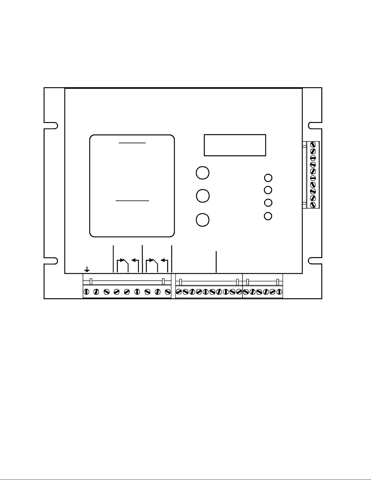
DESCRIPTION
The Model DS1522 Double Metal Sheet Detector comprises a control module in a sheet metal
housing with two probes to form a system that detects the thickness of metals passing between
the probes. The thickness is reported via two form C relays as “nominal”, “over”, “under” or
“nothing”. The DS1522 is capable of retaining up to 64 preset calibration setups which can be
invoked locally or remotely. This system may be used on automatic sheet feeders where
double or overlapped sheet material may jam or damage the receiving machine or ahead of roll
forming equipment to insure lap welds do not damage the equipment. A double feed or overlap
produces an output to stop the machine or signal the operator.
August 7, 2007
Page 2

DESCRIPTION
System Features
The DS1522 is a highly flexible gauging system with a variety of features, some of which may
be enabled or disabled through the positioning of DIP switches located beneath the control
module cover. The various features include:
• Accommodates a family of probes allowing double detection on metals, from foil to heavy
plate.
• Manual calibration on single and double thickness for all metals.
• Manual calibration on single thickness for steel.
• Automatic calibration on steel after material absence for a preset trigger time.
• Automatic calibration after lap welds of steel coil stock (Firmware Version 2.21 and up).
• Automatic nominal adjustment for roll stock of varying thickness.
• Independent over and under tolerance adjustment in 1 percent increments.
• Optional multiple calibration presets (up to 64).
• Local or remote selection of preset memories.
Each of these features is described in greater detail later in this document.
Control Module
The features of the control module include:
• Universal power input accommodates AC voltages from 100 to 240 volts.
• Removable terminal blocks for quick change-out of the control module.
• Separate form C relay outputs for independent reporting of OVER and UNDER conditions.
• LED indicators report the current gage states of NOTHING, UNDER, NOMINAL, and
OVER.
• Automatic setup
of system gain and operating parameters.
• External or front panel calibration through a contact closure or the front panel push-button
switch.
• Sixty four calibration memories that are selected through the DISPLAY/SELECT pushbutton
or optionally through an external parallel connection to a PLC or selector switch. These
memories allow quick changeover between materials of different nominal thickness. The
memory contents are retained even when power is removed from the unit.
• Latching OVER and UNDER outputs that are cleared by asserting the RESET input.
• A fast, open collector logic output that is ON for nominal readings and OFF for OVER or
UNDER.
• An open collector FAULT output that may be connected to a master controller for
monitoring fault and gauge-not-active conditions.
• Probe fault reporting on the digital display warns of broken or disconnected probes or cables.
2
Page 3

DESCRIPTION
Control Module Indicators
The function of the indicators and display on the DS1522 control module are described in the
following paragraphs:
1. OVER LED is ON whenever the material thickness exceeds the calibrated nominal value
by more than the set tolerance.
2. NOMINAL LED is ON whenever the received signal is within the specified tolerances,
both over and under.
3. UNDER LED is ON whenever there is material between the probes but the material thinner
than the calibrated nominal value by more than the set tolerance.
4. NOTHING LED is ON whenever the received signal goes beyond the measuring range of
the instrument indicating an absence of material between the probes.
5. The OVER, NOMINAL, UNDER, and NOTHING LEDs flash in succession when the
system is in calibrate mode.
6. Numeric Display indicates the level of the signal from the receiving probe and reports error
or status conditions. During gauge operation the value on the display reflects the strength
of the signal from the receiving probe. Thicker materials reduce the level of the signal
reaching the receiving probe, consequently the displayed value is lower for thicker material
and higher for thinner material.
Control Module DISPLAY/SELECT Pushbutton
Through the DISPLAY/SELECT pushbutton you can display the current local (Lc) preset
memory address if the DS1522 is off-line, i.e. the external enable signal is not asserted, or you
can display the current remote (rE) preset memory address if the GPIO signal is asserted. Thus
it is possible to determine if the unit is off-line or on-line by pressing the DISPLAY/SELECT
pushbutton and noting the identifier that displays. As long as the pushbutton is held, the
identifier displays. When the pushbutton is released, the currently selected preset address
displays for 5 seconds. The local address cannot be displayed if the DS1522 is on-line, i.e. the
external enable signal on the GPIO pin is asserted.
The local and remote addresses are independent values but they point to the same calibration
memories. When the external enable signal is asserted on the GPIO pin of the external select
port, the DS1522 is on-line and the remote address as applied to terminals IN1 through IN5 is
applied. The local address may not be displayed and changed while the DS1522 is on-line.
Conversely, the remote address may not be displayed while the DS1522 is off-line.
The local address can be changed by tapping the pushbutton while the value is displayed; the
remote address cannot. The remote address is determined by the signals entering the port at the
right of the control unit and cannot be changed locally. The local and remote addresses display
as a simple two digit number.
When the DISPLAY/SELECT pushbutton has been in the released state for 5 seconds, the
display reverts back to displaying gage information.
Control Module CALIBRATE GAP Pushbutton
The CALIBRATE GAP pushbutton initiates the gap calibration process. With no material
between the probes, press and hold the pushbutton for a minimum of three seconds to initiate
3
Page 4

DESCRIPTION
gap calibration. The system responds by displaying alternately gAP and SU until the
calibration process is complete. Calibration of the gap needs to be done once whenever the
probes are changed or the physical spacing of the probes changes.
Control Module CALIBRATE Pushbutton
The CALIBRATE push-button switch on the front panel of the control module serves to initiate
the calibration process and to make adjustments to several numeric parameters including the
upper tolerance (Ut), the lower tolerance (Lt), the automatic calibration trigger time (Ct), the
calibration delay time (Cd), and the relay delays (ry).
To initiate calibration, simply press the pushbutton and release it within 3 seconds.
To view the current value of a parameter, press the pushbutton and hold it for more than 3
seconds until the appropriate parameter identifier appears on the digital display. After the
parameter identifier appears, release the pushbutton and the current value of the parameter
displays for 5 seconds. To retain the current value of the parameter, simply allow the 5 second
display interval to elapse. The display reverts back to displaying signal strength.
To change the value of a parameter, press the pushbutton and hold it for more than 3 seconds
until the appropriate parameter identifier appears on the digital display. After the parameter
identifier appears, release the pushbutton and the current value of the parameter displays. Press
the pushbutton while the parameter is displaying and the value increments, first slowly then
more rapidly. For more precise control of the value adjustment, simply tap the pushbutton
repeatedly until the desired value is displayed. All parameters roll back to their minimum
values after reaching the maximum value. To retain the adjusted value of the parameter,
simply allow the 5 second display interval to elapse. The display reverts back to displaying
signal strength.
4
Page 5

DESCRIPTION
Control Module Configuration Switches
An eight position DIP switch is located beneath the front cover on the main control circuit
board to the left of the displays These switches must be set to enable the features of the system
that are appropriate to your application. Any time a switch setting is changed, the control
module must be powered down and back up to install the change. The switches are read only at
power up.
The functions of the switches are as follows:
Switch 1: OFF Disable automatic calibrate after double detection.
ON Enable automatic calibration after double detection (Version 2.1 and up)
Switch 2: OFF Automatic frequency selection during calibration.
ON Manual frequency selection (two-hit calibration only).
Switch 3: OFF Calibrate on single and double.
ON Calibrate on single only.
Switch 4: OFF Disable reference tracking.
ON Enable reference tracking.
Switch 5: OFF Slow memory changeover with address display
ON Rapid memory changeover, no address display (Version 1.7 and later)
Switch 6: OFF Disable automatic calibration trigger after material void.
ON Enable automatic calibration trigger after material void.
Switch 7: OFF Control interprets external selector port signals as high when activated.
ON Control interprets external selector port signals as low when activated.
Switch 8: OFF: The state of the relays for NOTHING in the gap is the same as for the
NOMINAL state.
ON: The state of the relays for NOTHING in the gap, is OVER for the OVER
relay and UNDER for the under relay.
Control Module Polarity Jumpers
Each of the logic inputs (CAL, RESET, and AUXIN) to the DS1522 has associated with it a
two position jumper plug located under the front cover and immediately behind its associated
connector. These jumpers allow the inputs to be driven by a sinking or sourcing device. When
the jumper plug is installed on the pins closest to the connector, the input is set up for a
sourcing driver. When installed on the two pins farthest from the connector, the input is set up
for a sinking driver, or dry contact between the input and COM.
Whether set for sinking or sourcing drivers, the input is active (ON) when the signal at the
terminal is low (at COM).
5
Page 6

APPLICATION CONSIDERATIONS
APPLICATION CONSIDERATIONS
Choice of Probes
The DS1522 accommodates a number of Prime probes but is most often used with the P1000B,
P70A, and P70CS probes. The P70A and P1000B probes are potted and completely sealed
units with permanently attached cables. The P70CS probes are potted with connectors for easy
removal. The same probe type is used for transmitter and receiver and is not polarized.
The table below provides rule of thumb information for probe selection.
Probe Housing Connection Gap Application
P1000B Aluminum block Cable 0.5” to 1.25” 0.060 and thicker
P70A Threaded steel barrel Cable 0.5” to 0.75” 0.004 to 0.060 steel
P70CS Smooth stainless barrel Connector 0.5” to 3.00” 0.004 to 0.060 steel
Probes with non-ferrous (aluminum and stainless steel) housings offer greater probe separation.
Probes with steel housings are not affected by the material used for mounting. Probes with
aluminum or stainless steel housings are affected by steel near them including mounting clamps.
To realize maximum separation with the P70CS type units, the probes must be mounted in nonferrous clamps, e.g. Nylatron or 303 stainless steel.
Prime offers a number of other probes that allow the DS1522 to be applied to a wide range of
materials including magnesium, copper, stainless steel, and aluminum. For more information or
assistance in selecting the appropriate probes, contact Prime Controls.
Calibration Considerations
The DS1522 offers four different modes of calibration.
1. Manual calibration on single and double thickness material (two-hit calibration). In this
mode, a sample of the nominal thickness is placed between the probes and the CAL
pushbutton or optional external cal switch is pressed. Then a second thickness (or multiples
of the original) are placed between the probes and the CALIBRATE pushbutton or external
cal switch is again pressed. Calibration is complete unless the tolerance value must be
adjusted.
2. Manual calibration on single thickness steel (single-hit calibration). In this mode, calibration
can be initiated through a press of the CALIBRATE pushbutton or an optional external cal
switch prior to material entering the gap between the probes. The DS1522 enters a wait state
until material is fed between the probes. If the calibration delay parameter (Cd) is set to
zero, calibration occurs within 100 milliseconds after material is sensed between the probes.
For slow moving material, this delay can be increased (up to 9.9 seconds) to insure the
material fully covers the probes before calibration occurs. See the Control Module
CALIBRATE Pushbutton section earlier in this document for the parameter adjustment
procedure.
6
Page 7

APPLICATION CONSIDERATIONS
3. Automatic calibration on single thickness steel after coil change (Switch 6 ON). In this
mode, calibration process is the same as for the manual single-hit calibration except that the
calibration process can be initiated by the expiration of a timer within the DS1522. The
timer can be set to a value from 0.1 minute (6 seconds) to 25 minutes. When the DS1522
detects the absence of material between the probes, the timer count-down begins. If the
count-down expires before material is sensed, the DS1522 enters calibration mode, waiting
for material to be fed. If the calibration delay parameter (Cd) is set to zero, calibration
occurs within 100 milliseconds after material is sensed between the probes. For slow moving
material, this delay can be increased (up to 9.9 seconds) to insure the material fully covers
the probes before calibration occurs. See the Control Module Calibrate Pushbutton
section earlier in this document for the parameter adjustment procedure.
4. Automatic calibration on single thickness steel after double (overlap) detected (Switch 1
ON). In this mode, available in systems with Firmware Version 2.1 and higher, the
calibration process is the same as for modes 2 and 3 above except that the calibration process
is initiated by the occurrence of a lap weld or overlap in the incoming material. When the
OVER condition is detected, the OVER relay switches for a minimum of 25 milliseconds and
then after the programmed calibration delay (Cd) calibration commences. The intent of this
mode is to detect lap joints and provide automatic recalibration on the material following the
lap joint.
When automatic calibration after double is enabled (Switch 1 ON), the calibration delay (Cd)
parameter may be used to insure calibration occurs beyond the overlap area. However,
should calibration occur on the overlap, the detection of an under condition after the overlap
will initiate recalibration if the under tolerance is set appropriately. The delay of relay
response through the “ry” parameter may still be used in this mode. However for detection
of short overlaps it may be necessary to set the relay delay to zero for fastest gauge response.
The choice of calibration mode is application dependent since each mode has its advantages and
disadvantages. Two-hit calibration offers the possibility of discriminating changes in metal
thickness that are far less than 2 to 1 since the system is calibrated on samples of the thickness
range to be discriminated.
Relay Response Time
For most applications it is desirable that the OVER relay respond as quickly as possible. For
thinner materials the response time is as fast as 3 milliseconds. For very thick metals the
response time can be as long as 40 milliseconds.
If very fast response times are undesirable, the action of the relays can be delayed through the
adjustment of the relay delay parameter (ry). This parameter represents a time interval in
fractions of a second from .00 to .99 seconds. To adjust the delay value, press and hold the CAL
pushbutton until the identifier “ry” appears on the two digit display. Release the pushbutton and
observe the current value of the delay parameter. Press and/or tap the CAL pushbutton as
necessary to bring the delay parameter to the desired value. To retain the adjusted value of the
parameter, simply allow the 5 second display interval to elapse. The display reverts back to
7
Page 8

APPLICATION CONSIDERATIONS
displaying signal strength. See the Control Module Calibrate Pushbutton section earlier in
this document for the parameter adjustment procedure.
Tracking Nominal
The tracking nominal feature of the DS1522 (Switch 4 ON) is typically used on roll-fed material
that varies in thickness over its length. The unit keeps a slow average of the thickness and
gauges relative to the average rather than relative to a fixed nominal calibration value. The
average is referred to as the tracking nominal. The tracking nominal is allowed to shift by as
much as 50% in thickness in either direction from the calibrated nominal.
Whenever no material is sensed between the probes, the calibrated nominal is reinstated
regardless of the final thickness of the previous material.
Gauge and Fault Monitoring
The open collector FAULT output provides a means for monitoring the status of the DS1522
to insure that all material passing between the probes is checked for doubles. When the DS1522
controller detects a probe fault or a fault within the controller itself, the FAULT output turns
OFF. Since OFF is the fault state, a loss of power to the DS1522 is reported as a fault.
The FAULT output also turns off whenever the controller is not in gauge mode, i.e. whenever
the unit is in setup (SU) or calibration (CA) mode.
8
Page 9

INSTALLATION
INSTALLATION
The installation of the components of the DS1522 system is covered in the following
paragraphs:
DS1522 Control Module
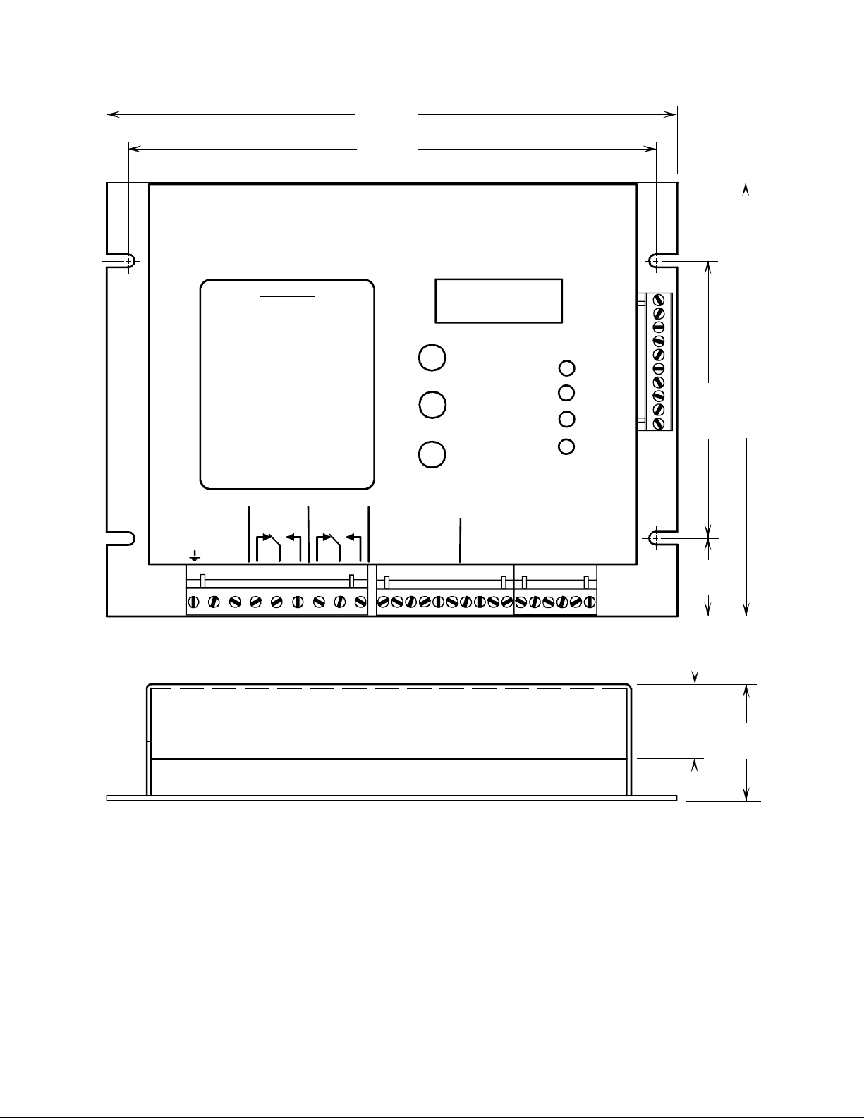
The control board is designed to mount on the back panel of an electrical enclosure using the
four mounting slots at the edges of the enclosure. The footprint is 8.25 inches (210 mm) by 6.25
inches (159 mm) with mounting slot locations on a rectangle 7.625 inches (194 mm) in the
horizontal and 4.0 inches (102 mm) in the vertical. Insure that the mounting screws make good
electrical contact between the module housing and the control enclosure back panel.
Avoid mounting locations with excessive heat and vibration.
Probe Mounting
See instructions specific to the probes supplied with your system.
Electrical Wiring
All wiring for the DS1522 connects to removable terminal blocks at the bottom of the control
enclosure as described in the following paragraphs.
1. Connect 100 to 240 VAC, 50-60 Hz. power (15 watts) to the terminals labeled AC on the
leftmost terminal block.
2. Connections to the control circuit of the machine are made through the OVER and UNDER
form C relays as required. These relays are powered in the NOMINAL condition and the
diagram on the DS1522 front panel reflects the NOMINAL state. As shipped from the
factory, the NOTHING state places the relays in the same state as NOMINAL. DIP switch
8, beneath the cover of the DS1522, when ON, causes the NOTHING condition to place the
OVER and UNDER relays in the over and under states simultaneously.
3. The shielded cables from the probes to the board should be run in conduit. The receiver
probe is connected to terminals labeled RCVR on the rightmost terminal block and the
transmitter probe to the terminals labeled TMTR on the same terminal block. Since the
probes are non-polarized, the order of lead connection is not important and since the probes
are identical, it does not matter which is the transmitter and which is the receiver. Connect
the shield leads (drain wires) from the probe cables to the terminals labeled SHLD.
4. The OVER and UNDER relays may be operated in a "follower" mode or a "memory" mode
depending upon the wiring of the RESET input. The operational modes and required
connections are described below.
a) For "follower" mode, jumper RESET and COM together on the center terminal block. In
this mode, when an OVER or UNDER condition occurs, the appropriate relay drops out,
and the OVER or UNDER LED comes on. After the fault condition is corrected, the relay
returns to the normally energized condition and the LED goes out. Automatic reset is
normally selected to control the operation when the fault condition is automatically
removed or the DS1522 is wired into the stop circuit of the machine.
9
Page 10

INSTALLATION
b) For "latch" mode, wire the RESET and its associated COM terminal to the normally open
contacts of a switch, relay, or controller output. In this mode, when a fault condition
occurs, the relay drops out and the OVER or UNDER LED comes on. After the fault
condition is corrected, the contact must be momentarily closed to energize the relay.
5. Optionally, the open collector FAULT output may be connected to a master system
controller or to an indicator that warns of an error condition within the DS1522 system.
This output is normally ON and turns OFF when an error condition is detected. Thus if the
DS1522 loses power, the FAULT output reports an error condition by default.
The FAULT output turns OFF any time the DS1522 is not gauging the metal between the
probes. In addition to error conditions, setup (SU on the display) and calibration (CA on
the display) cause the fault output to turn OFF. This allows the unit to be monitored for
non-gauge conditions.
Optional Remote Preset Calibration Selection
The 10 terminal connector at the right side of the DS1522 chassis provides a means to control
the selection of calibration presets from an external switch or remote controller such as a PLC
(See illustrations on following page). The rightmost terminals labeled IN6 through IN1 accept
signals in binary combination to select preset memories numbered from 0 through 63. IN1 is
the least significant bit. Thus the addresses are formed as follows:
IN6 IN5 IN4 IN3 IN2 IN1 ADDRESS
off off off off off off 00
off off off off off on 01
off off off off on off 02
-
-
on on on on on off 62
on on on on on on 63
The GPIO terminal (4
th
from the bottom) is the “enable” signal. When asserted, this signal tells
the control module to use the address applied to terminals IN1 through IN6 for preset calibration
selection. When enable is not asserted, the control module uses the local address as programmed
through the DISPLAY/SELECT pushbutton for preset calibration selection. See the section on
Control Module DISPLAY/SELECT Pushbutton earlier in this document.
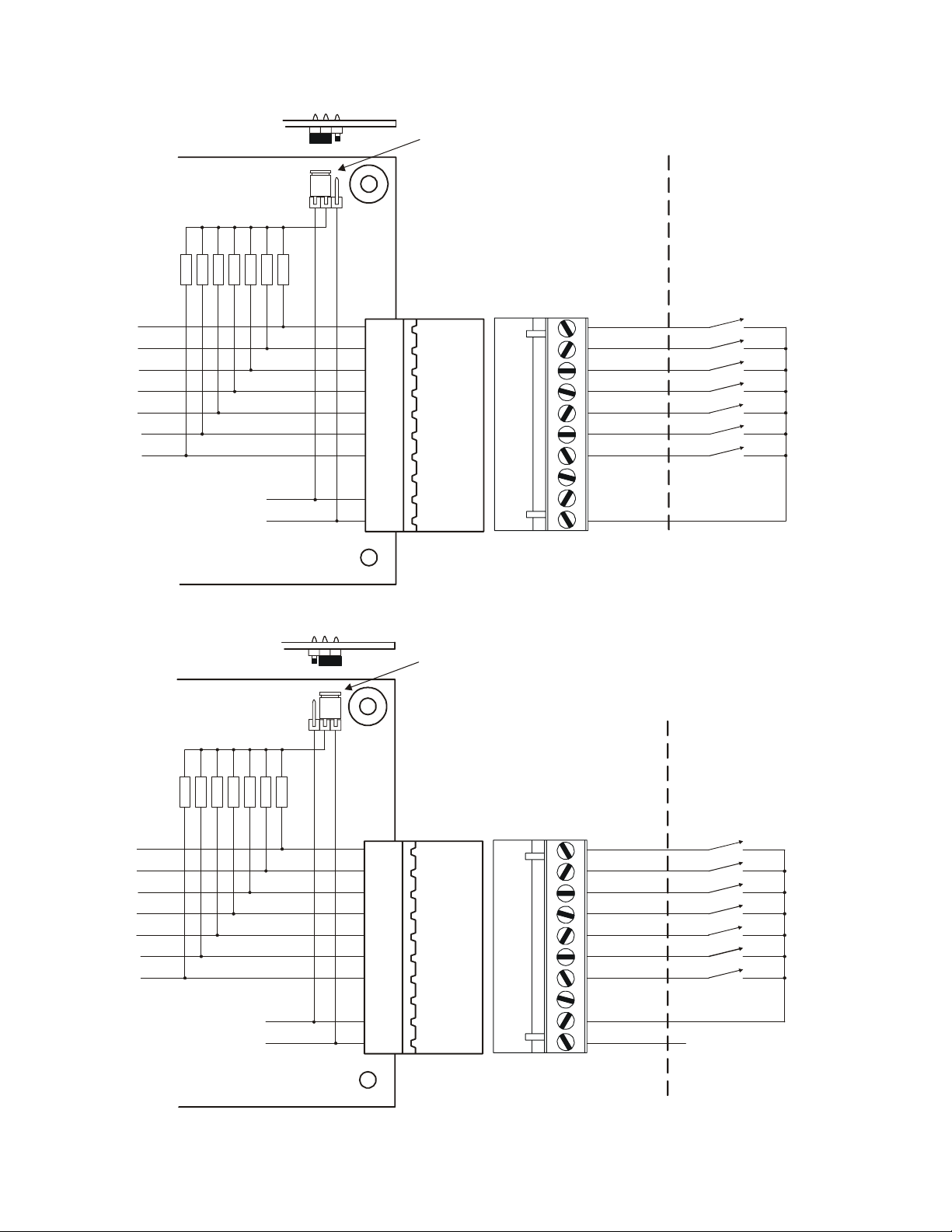
These inputs may be set to accommodated either sinking (open collector) or sourcing (PNP)
drivers. All inputs are set to the same mode; mixed modes are not allowed. A two position
jumper plug in the upper right corner of the I/O board (accessible from the top when the cover is
removed) connects the inputs through 4700 ohm resistors to +15 volts when in the left position
(center and left pin connected), or to ground (COM) when in the right position (center and right
pin connected). Typically the jumper is placed in the left position for sinking drivers and in the
right position for sourcing drivers.
Additionally, DIP switch 7 (seventh from the top) tells the control module if the inputs are active
when high (Switch 7 OFF – to the left) or active when low (Switch 7 ON – to the right).
Typically Switch 7 is OFF for sourcing drivers and ON for sinking drivers.
10
Page 11
INSTALLATION
A
A
4.7K
4.7K
TO INTERNAL LOGIC
SYSTEM COMMON
4.7K
4.7K
+15V
Install Jumper Plug as shown
and set Switch 7 ON
PLC Sinking Output
Drivers or
Manual Switch to
4.7K
4.7K
4.7K
Common or
Relays to Common
IN1
IN2
IN3
IN4
IN5
IN6
GPIO
OUT1
+15V
COM
4.7K
4.7K
4.7K
4.7K
TO INTERNAL LOGIC
+15V
SYSTEM COMMON
CTIVE-LOW DRIVER
CONFIGURA TION
Install Jumper Plug as shown
and set Switch 7 OFF
PLC Sourcing Output
Drivers or
Manual Switch to
4.7K
4.7K
4.7K
IN1
IN2
IN3
IN4
IN5
IN6
GPIO
OUT1
+15V
COM
+12V to +24V or
Relays to
+12V to +24V
To PLC Common
CTIVE - H IG H DRIVER
CONFIGURA TION
11
Page 12

SETUP
INITIAL SETUP
Probe and Gap Assessment
The startup process of the DS1522 commences immediately after power up and includes
several processes which are transparent to the user except for the sequence of characters that
appear on the two digit display.
When the unit first powers up, the probes are analyzed to determine the type or probe attached to
the control unit. While the assessment is in process, the letters Pr flash on and off. When the
type of probe has been established, the probe identifier flashes alternately with Pr for
approximately 3 seconds. The probe identifiers include 15, 70, and 1H. After identifying the
probes, the control module determines which calibration preset is to be used and then displays
alternately SL and the preset number, e.g. SL 01. If the probes are faulty, disconnected, or
cannot be identified, the controller flashes PR 01 indefinitely.
After the probes have been identified and the calibration memory selected and displayed, the
control module begins displaying the signal strength from the receiving probe. If the system
has been newly installed or the relative positions of the probes has been changed, it is
necessary to “calibrate the gap”. With no material between the probes, press and hold the
CALIBRATE GAP pushbutton for three seconds until the letters SU and gAP flash alternately
on the display. The system records the “no material condition” in non-volatile memory. When
the display reverts to displaying signal strength, the gap calibration process is complete. It is
essential that for this assessment there is no material between the probes.
When the operating conditions have been established, the two digit readout displays a numeric
value representing the receiver signal strength.
Gauge Tolerance Adjustment
When the startup sequence has been completed and if the probes are successfully identified, the
system enters gauge mode and displays the receiver signal strength on the two digit display. At
this point the gauging tolerances should be verified and/or set as described below: If more than
one calibration memory is to be used, the tolerances must be adjusted independently for each
stored calibration. The tolerance adjustments may be done any time except when the system is
in calibration mode (displaying “CA”).
1. Press and hold the calibration pushbutton for 3 seconds or until the unit displays “Ut”
(Upper tolerance). Release the pushbutton and observe the setting for the upper tolerance
value. The tolerance displays as a percentage of the single thickness and can be adjusted
from a value of 1 to 99. If the pushbutton is not pressed again within 5 seconds, the display
reverts back to displaying gauge signal strength and the current upper tolerance value is
retained. To change the upper tolerance, tap or hold in the pushbutton as necessary to
adjust the upper tolerance to the desired value. For detection of doubles, 50% is a good
value. Retain and store the displayed value by releasing and not activating the pushbutton
for 5 seconds. The display reverts back to showing signal strength.
2. Press and hold the calibration pushbutton for 4.5 seconds or until the unit displays “Lt”
(Lower tolerance). Release the pushbutton and observe the setting for the lower tolerance
value. The tolerance displays as a percentage of the single thickness and can be adjusted
from a value of 1 to 99. Tap the pushbutton as necessary to adjust the lower tolerance to
the desired value. If gauging for “under” is of no interest, set the lower tolerance to a high
value such as 99%. Retain the displayed value by releasing and not activating the
pushbutton for 5 seconds. The display reverts back to showing signal strength.
12
Page 13

SETUP
Relay Response Time
Check that the relay response time is appropriate for your application. The relay delay parameter
current value can be viewed by pressing and holding the CAL pushbutton until the “ry”
identifier appears on the two digit display. Release the pushbutton and observe the current value
of the delay parameter. Press and/or tap the CAL pushbutton as necessary to bring the delay
parameter to the desired value. To retain the adjusted value of the parameter, simply allow the 5
second display interval to elapse. The display reverts back to displaying signal strength.
The delay value displays in seconds and can be adjusted from zero (.00) to .99 seconds.
13
Page 14

CALIBRATION
CALIBRATION
The DS1522 offers three modes of calibration: 1) manual calibration on single and double
material samples, 2) manual calibration on a single thickness material sample, and 3)
automatic calibration on material coming between the probes after a period of no material
between the probes.
Calibration on Single and Double Thickness
For highest gauging precision, the double sheet detector must be calibrated on both a single and
a double thickness of the material to be monitored, any time prior to running. This mode of
calibration is selected when Switch 3 is OFF. Calibration values are retained even when power
is removed from the DS1522. Depending upon selected options, the system can retain one,
two, or up to 64 different calibration settings in non-volatile memory. See the separate section
on Multiple Calibration Memories. To calibrate on single and double, proceed as follows:
1. Place a single sheet of the thickness to be gauged in the probe gap and press the CAL
pushbutton or close a contact across the external CAL input. If the calibration on single is
accepted, the unit displays alternately "CA" and "2" indicating readiness to calibrate on a
double thickness. If the calibration is not successful, the unit displays alternately "CE" and
a number. Calibration may be attempted again immediately.
2. Place a double thickness of material to be gauged in the probe gap and press the CAL
pushbutton or close a contact across the external CAL input. If the calibration is
successful, the unit resumes display of the signal strength. If the calibration is not
successful, the unit displays alternately "CE" and a number. If this occurs, reinsert the
single thickness and begin calibration again.
3. Adjust the gauge tolerance values if necessary (See Gauge Tolerance Adjustment under
INITIAL SETUP) and proceed with normal operation.
Manual Calibration on Single Thickness
Manual calibration on single thickness is selected when Switch 3 is ON and Switch 6 is OFF. If
you change the switch settings, be sure to power the unit down and back up to activate the new
settings. The switches are read only at power-up.
When calibrate-on-single is selected, the calibration process may be triggered in two ways: by
the press of the front panel pushbutton, or by a 30 millisecond or longer contact closure between
the external CAL input and COM.
Place a single sheet of the material to be gauged in the probe gap and press the CAL
pushbutton or close a contact across the external CAL input. If the calibration-on-single is
accepted, the unit displays alternately "Fr" and a number indicating the frequency selected for
operation. The displayed number has no meaning except for factory troubleshooting.
If the control senses no material between the probes when the CAL pushbutton is pressed or the
external CAL input is activated, it enters a wait state, flashing “CA” on the display until
material is brought between the probes. An additional calibration delay can optionally be
introduced through the calibration delay parameter (Cd). If not zero, this delay holds off the
calibration process for the specified delay time after material comes between the probes to
insure the material fully covers the probes during calibration. The additional delay may be
14
Page 15

CALIBRATION
required with slow-moving material. See the Calibration Delay Time section later in this
document for the parameter adjustment procedure.
Gauging commences immediately after calibration but only if the pushbutton is released and
the contact across CAL and COM is released. If either of the calibration initiating signals
persists, the unit hangs in a wait state.
Automatic Calibration on Single Thickness
Two switches must be properly set to enable automatic calibration. The system must be enabled
for calibrate on single (Switch 3 ON) and automatic calibration must be enabled (Switch 6 ON).
These switches must be set prior to powering the unit since they are read-only at power-up.
Automatic calibration provides a time-based trigger that starts the calibration process. Whenever
there is no material between the sensing probes for a time equal to or greater than the stored
trigger interval (see Auto-cal Trigger Time later in this document), the DS1522 enters a wait
state in preparation for calibration when material comes between the probes. The display flashes
alternately “CA” and blank and the LEDs flash sequentially. The wait for material can be
indefinite.
When material enters the gap between the probes, if the calibration delay parameter (Cd) is set
to zero, calibration occurs within 100 milliseconds. For slow moving material, this delay can be
increased (up to 9.9 seconds) to insure the material fully covers the probes before calibration
occurs. With no programmed delay, typical calibration time is 300 milliseconds, total. See the
Calibration Delay Time section later in this document for the parameter adjustment procedure.
If material comes between the probes before the trigger interval times out, the timer is reset to its
programmed value.
When automatic calibration is enabled, the calibration process may still be initiated by a press of
the CALIBRATE pushbutton or a contact closure between CAL and COM. Actual calibration
will begin only when material is sensed between the probes and the calibration delay has timed
out.
Multiple Calibration Memories
The DS1522 can store up to 64 calibration settings for later recall. Each calibration is saved in a
distinct memory location with an address of 0 through 63. The calibration memory address may
be selected through the front panel using the DISPLAY/SELECT pushbutton (local selection) if
the GPIO signal on the right side connector is not
asserted. If the GPIO signal is asserted, the
memory address must be selected through the IN1 through IN5 terminals of the right side
connector (remote selection). See Control Module DISPLAY/SELECT Pushbutton and
Optional Remote Preset Calibration Selection sections earlier in this document.
To save a calibration setup to a specific memory location, first set the desired memory address
either locally with GPIO not asserted or remotely with GPIO asserted. Then proceed through the
15
Page 16

CALIBRATION
normal calibration process as described above. For additional calibrations, select a new address
and repeat calibration for the new metal samples.
CAUTION: The locally selected memory address and the remotely selected memory address
are independent values and may point to two different memory locations. When GPIO is
asserted, the calibration values from the remotely selected memory location will be active.
When GPIO is not asserted, the calibration values from the locally selected memory location will
be active. If the local address is the same as the remote address, the same calibration values will
be selected with GPIO asserted or not asserted.
Auto-cal Trigger Time
The trigger time interval for automatic calibration can be set by the operator through the
CALIBRATE pushbutton on the front panel of the DS1522 control unit. The interval is set in
increments of 6 seconds (0.1 minutes) from 0 to 3 minutes, in increments of 12 seconds (0.2
minutes) from 3 to 5 minutes, in increments of 30 seconds (0.5 minutes) from 5 to 10 minutes,
and in increments of 1 minute from 10 to 25 minutes. To set the trigger time interval, do the
following:
1. Insure that the unit is not attempting to calibrate (no “CA” flashing on the digital display). If
“CA” is flashing, place a piece of material between the probes and allow the calibration
process to be completed. Calibration and time parameter adjustment are mutually exclusive
processes.
2. Hold the CALIBRATE pushbutton in for approximately 6 seconds or until “Ct” appears on
the digital display. Prior to displaying “Ct”, the DS1522 displays “Ut” followed by “Lt”
(for upper tolerance and lower tolerance adjustment). WARNING: If the pushbutton is
released before 3 seconds, the DS1522 begins the calibration process.
3. When “Ct” displays, release the pushbutton and the trigger time interval is displayed on the
digital readout. If the pushbutton is not pressed again within 5 seconds, the display reverts
back to displaying gauge signal strength and the current time value is retained.
4. Whenever the time interval is displaying, the pushbutton may be pressed to increment the
time to the desired value. The time value is incremented one resolution unit with every press
and release of the pushbutton. If the pushbutton is held in, the value auto-increments at an
ever increasing rate until the pushbutton is released. The value increments up to a maximum
of 25 minutes and then rolls back to 0.1 minutes.
5. When the time has been adjusted to the desired value, it displays for 5 seconds (assuming the
pushbutton is not pressed again) and then is accepted and saved in non-volatile memory. The
display reverts back to displaying signal strength.
16
Page 17

CALIBRATION
Calibration Delay Time
The “Cd” parameter specifies the duration of a time delay that applies to single sample
calibration, in both manual and automatic trigger modes. The sequencing is as follows:
1. Calibration is triggered, either manually or through trigger time-out.
2. The system waits indefinitely until metal is detected between the probes.
3. When metal is detected, the calibration delay time-out begins.
4. When the calibration delay has timed out, calibration begins.
5. When calibration is complete, gauging begins.
The calibration delay interval can be set to any value between 0.0 and 9.9 seconds. To set the
calibration delay time, proceed as follows:
1. Insure that the unit is not attempting to calibrate (no “CA” flashing on the digital display). If
“CA” is flashing, place a piece of material between the probes and allow the calibration
process to be completed. Calibration and time parameter adjustment are mutually exclusive
processes.
2. Hold the CALIBRATE pushbutton in for approximately 6 seconds or until “Cd” appears on
the digital display. Prior to displaying “Cd”, the DS1522 displays “Ut” followed by “Lt”
and then, if auto-cal is enabled, by “Ct”. WARNING: If the pushbutton is released
before 3 seconds, the DS1522 begins the calibration process.
3. When “Cd” displays, release the pushbutton and the calibration delay time interval is
displayed in seconds on the digital readout. If the pushbutton is not pressed again within 5
seconds, the display reverts back to displaying gauge signal strength and the current delay
value is retained.
4. Whenever the time interval is displaying, the pushbutton may be pressed to increment the
time to the desired value. The time value is incremented one resolution unit with every press
and release of the pushbutton. If the pushbutton is held in, the value auto-increments at an
ever increasing rate until the pushbutton is released. The value increments up to a maximum
of 9.9 seconds and then rolls back to 0.0 seconds.
5. When the time has been adjusted to the desired value, it displays for 5 seconds (assuming the
pushbutton is not pressed again) and then is accepted and saved in non-volatile memory. The
display reverts back to displaying signal strength.
17
Page 18

SPECIFICATIONS
SPECIFICATIONS
Power Requirements
AC Power, 90 to 240 volts, 15 watts.
Logic Input Electrical Specifications
CAL, RESET, AUXIN: 30 Volts maximum
Upper switch threshold - 6.9 volts
Lower switch threshold - 3.3 volts
When the internal jumper is installed for pull up to accommodate sinking drivers, the input is
pulled to +15 volts through 4700 ohms. When the jumper is installed for pull down to
accommodate sourcing drivers, the input is pulled to common through 4700 ohms.
Logic Output Electrical Specifications
AUXO, FAULT: NPN open collector, 100mA max., 50 volts max.
Output Relay Specifications
Maximum switched voltage: 380VAC
Maximum switched current: 14 amps N.O., 5 amps N.C, AC resistive,
8 amps DC
Maximum switched power: 200W DC, 2,000VA AC.
Minimum required contact load: 12V, 100 mA
Expected mechanical life: 20 million operations
Expected electrical life: 100,000 operations at 8 amps, 240VAC
50,000 operations at 14 amps N.O., 5 amps N.C.,
120VAC resistive
30,000 operations at 7.2FLA, 45LRA, 120VAC
10,000 operations at 5FLA, 30 LRA, 240VAC
Selector Port Electrical Specifications
IN1, IN2, IN3, IN4, IN5, IN6, GPIO
Input resistance: 4,700 ohms
Pullup voltage (jumper set left): 15 volts
Max input voltage: 30 volts
On threshold: 6.9 volts
Off threshold: 5 volts
Response time: 100 microseconds
18
Page 19

TROUBLESHOOTING
TROUBLESHOOTING
Should trouble develop, proceed as follows:
1. If no indicators or displays are illuminated, check AC input power to the control module
and the fuse located on the lower left of the chassis.
2. If the unit powers up but hangs displaying alternately “Pr” and “01”, the transmitter probe
is either not connected, is shorted, or has an open in the wiring.
3. If the unit powers up, initializes and the LEDs indicate a response to the material in the gap
but the relays do not switch, check that the relays are set to follow and not to latch (activate
the RESET input to unlatch). For most installations, simply install jumpers between
RESET and COM.
4. IF “PR” and “01” flash alternately on the display, check the transmitting probe for proper
connection and continuity.
5. IF “PR” and “02” flash alternately on the display, check the receiving probe for proper
connection and continuity.
6. IF “PR” and “03” flash alternately on the display, check both probes for proper connection
and continuity.
7. If the DS1522 hangs displaying alternately “gAP” and “CA”, the control module has
determined that the gap has not been calibrated. Remove all material from between the
probes then press and hold the CALIBRATE GAP pushbutton for a minimum of three
seconds (until the unit begins displaying alternately gAP and SU.
8. If the DS1522 hangs displaying alternately SL and Er, an invalid preset calibration address
is being applied to the external preset select port.
9. If the unit flashes alternately “Er” and a numeric value between 1 and 5, perform the
corrective action prescribed in the table below. If the error persists, consult the factory.
“Er” Number Fault Description Correction
01 PSD RAM failure Reset through power down
02 Display shift register failure Reset through power down
03 Input shift register failure Reset through power down
04 Control shift register failure Reset through power down
05 Digital synthesizer failure Reset through power down
08 ystem configuration data fault Reset through power down
10. During manual calibration on single and double, errors may occur that are reported through
the alternate display of “CE” and a numeric value of 1 or 2. These error codes have the
following meanings:
“CE” Number Interpretation
01 The single thickness material is too thin for the system as
configure with the current probes.
02 The material is too thick for the system as configured with
the current probes.
19
Page 20

TROUBLESHOOTING
11. After calibration the LEDs on the DS1522 flicker between NOMINAL and OVER or
between NOMINAL and UNDER or between all three. Usually this indicates that the
tolerances are too tight. Adjust the tolerances through the CAL pushbutton as described
earlier in this document under Gauge Tolerance Adjustment in the SETUP section.
Firmware Version
From time to time, as improvements are made to Prime products, the firmware controlling the
units is revised. When setting a unit up or troubleshooting it may be necessary to determine the
version number for the firmware installed in your unit. The version numbers begin with 1.0 and
are incremented either by tenths (1.1, 1.2, etc.) for small revisions or by the integer digit (1.0,
2.0, etc.) for more significant revisions.
To determine the version of the firmware running in your unit, simply hold the calibration
pushbutton in as power is applied to the unit. The revision number will be displayed on the twodigit display alternately with the letters “Fr”. For example, Version 1.8 will flash alternately
“Fr” and “1.8”.
For further information or service assistance, contact Prime Controls, Inc., 4551 Gateway
Circle, Dayton, Ohio. Phone: (937) 435-8659. Mention model number and serial number.
20
Page 21
209.6
(8.25)
193.7
(7.625)
®
RIME
DS1522
DOUBLE SHEET DETECTOR
MESSAGES
Probe identification
Pr nn -
Selector switch position
SL nn -
Calibration Mode
CA -
flashing - Calibration fault
CE nn
flashing - Tx Probe fault
Pr 01
flashing - Rx Probe fault
Pr 02
flashin g - Tx & Rx Probe fault
Pr 03
flashing - Fatal system fault
Er nn
(Press CAL button for 3 seconds)
Lt Ut Ry Ct Cd -
PARAMETERS
Lower tolerance
Upper tolerance
Relay response delay
Calibration trigger time
Calibration delay time
DISPLAY/SELECT
CALIBRATE GAP
CALIBRATE
P
CONTROLS, INC.
SIGNAL/MESSAGE
OVER
NOMINAL
UNDER
GAP
(4.0)
101.6
(6.25)
158.8
POWER OVER UNDER
100 - 240 AC
RELAY
AC
AC
RELAY
CONTROL I/O PROBES
CAL
INPUTS
RESET
COM
OUTPUTS
COM
AUXO
AUXIN
COM
COM
COM
FAULT
TMTR
TMTR
SHLD
RCVR
RCVR
SHLD
28.6
(1.125)
24.8
(0.975)
41.3
(1.625)
21
Page 22

®
RIME
DS1522
DOUBLE SHEET DETECTOR
MESSAGES
Probe identification
Pr nn -
Selector switch position
SL nn -
Calibration Mode
CA -
flashin g - Calibr ation fau lt
CE nn
flashing - Tx Probe fault
Pr 01
flash in g - Rx Pr ob e f au lt
Pr 02
flashing - Tx & Rx Probe fault
Pr 03
flashing - Fatal system fault
Er nn
(Press CAL bu tton for 3 seconds)
Lt Ut Ry Ct Cd -
PARAMETERS
Lower tol er an c e
Upper tol er an c e
Relay res pon s e delay
Calibration trigger time
Calibration delay time
DISPLAY/SELECT
CALIBRATE GAP
CALIBRATE
P
CONTROLS, INC.
SIGNAL/MESSAGE
OVER
NOMINAL
UNDER
GAP
SAFETY GND
AC POWER
CONTROL
INTERLOCK
OPEN FOR DOUBLE
POWER OVER
100 - 240 AC
AC
RELAY RELAY
AC
CONTROL
INTERLOCK
OPEN FOR UNDER
OPTIONAL
REMOTE CAL
OPTIONAL
OUTPUT LATCH RESET
JUMPER SOLID IF LATCHING
OUTPUT NOT DESIRED
UNDER
CONTROL I/O
INPUTS
CAL
COM
RESET
OUTPUTS
COM
COM
AUXO
AUXIN
COM
PROBES
RCVR
RCVR
SHLD
TMTR
TMTR
COM
FAULT
SHLD
TO PROBES
FAULT SIGNA L
NPN, OPEN COLLECTOR
100 mA MAX., OFF = FAULT
HOOKUP IS OPTIONAL
FAST RESPONSE OUTPUT
NPN, OPEN COLLECTOR, 100 mA MAX.
OFF FOR OVER OR UNDER, NO DELAY.
NOT AVAILABLE IF SM10 SWITCH
MODULE OPTION IS INSTALLED.
TRANSMITTER
RECEIVER
3. MAINTAIN INDEPENDENT SHIELDS
4. POSITION SHIELD TERMINALS BET W EEN
TRANSMITTER AND RECEIVER SIGNAL
TERMINALS
TRANSMITTER
RECEIVER
FOR MAXIMUM NOISE IMMUNITY, SPLICE
OR TERMINATE CABLES ONLY WHEN
ABSOLUTELY NECESSARY.
WHERE EXTENSION IS NECESSARY,
USE BELDEN 8761 OR EQUIVALENT
SHIELDED, TWISTED PAIR CABLE.
THE DS1520 IS DESIGNED TO PROVIDE
HIGH COMMON MODE NOISE REJECTION.
COMMON MODE REJECTION IS REALIZED
MOST EFFECTIVELY WITH TWISTED PAIR CABLING.
Page 23

LIMITATION AND EXCLUSION OF WARRANTIES
All goods purchased from Prime Controls, Inc. shall be free from defects in materials, design and
workmanship under normal conditions of use for one year from the date of shipment. THIS
WARRANTY IS THE SOLE WARRANTY AND IS EXPRESSLY IN LIEU OF ALL OTHER
WARRANTIES, EXPRESSED OR IMPLIED, INCLUDING BUT NOT LIMITED TO ANY
IMPLIED WARRANTY OF MERCHANTABILITY OF FITNESS FOR A PARTICULAR
PURPOSE. THE LIABILITY OF PRIME CONTROLS TO ANY PURCHASER SHALL BE
LIMITED EXCLUSIVELY TO THE COST OF REPLACEMENT OR REPAIR OF
DEFECTIVE PARTS, AND SHALL NOT INCLUDE LIABILITY FOR ANY DIRECT,
CONSEQUENTIAL OR INCIDENTAL DAMAGES WHATSOEVER, WHETHER
FORESEEN OR UNFORESEEN, INCLUDING BUT NOT LIMITED TO LOST PROFITS,
LOST SALES, OR INJURY TO PERSONS OR PROPERTY. 9/25/97
23
 Loading...