

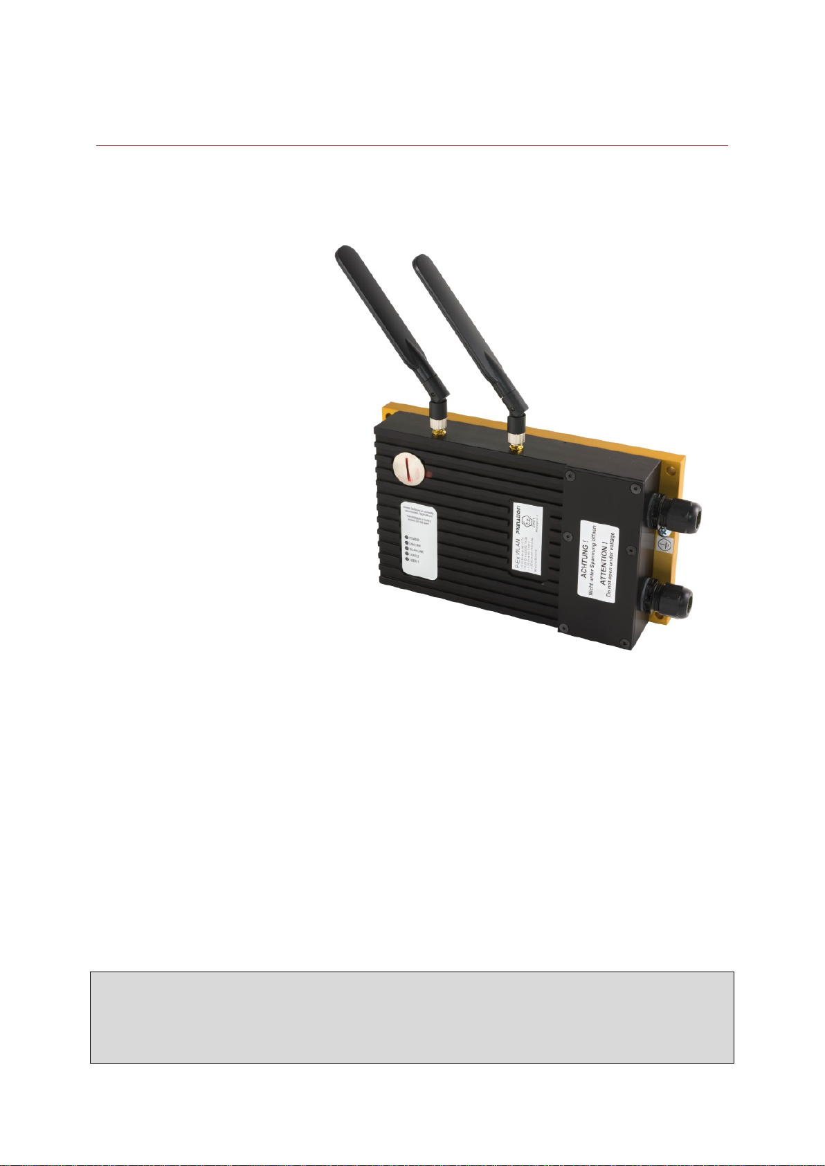
Bedienungsanleitung
WLAN Access Point
Typ P-Ex WLAN-DC-A
Typ P-Ex WLAN-DC-S
ATEX Version
Zone 1/21/M2
Version: 1.2
Stand: 02.08.2017
Technische Änderungen vorbehalten!
Inhalt Seite
Deutsch 1-18
Englisch 19-37
PRIMATION Systemtechnik Tel.: +49 (0)89 46 26 0 - 0
GmbH & Co. KG Fax: +49 (0)89 46 26 0 - 210
Bretonischer Ring 13 Mail: info@primation.de
85630 Grasbrunn Web: http://www.primation.de
Deutschland

Inhalt
1. Wichtige Hinweise zur Bedienungsanleitung .............................................................................. 1
1.1. Hinweise zur Bedienungsanleitung ..................................................................................... 1
1.2. Piktogramme und Sicherheitshinweise ............................................................................... 1
1.3. Allgemeine Hinweise........................................................................................................... 2
2. Informationen zum Produkt ........................................................................................................ 4
2.1. Hersteller ............................................................................................................................ 4
2.2. Explosionsschutz ................................................................................................................ 4
2.3. Technische Daten ............................................................................................................... 4
2.4. Typnummern ...................................................................................................................... 5
2.5. Verwendung ....................................................................................................................... 5
3. Inbetriebnahme des P-Ex WLAN Access Point .......................................................................... 6
3.1. Informationen zum Aufbau des P-Ex WLAN ....................................................................... 6
3.2. Bedeutung der Leuchtdioden .............................................................................................. 7
3.3. Pinbelegung P-Ex WLAN Versorgungsstromkreis X1-X5 .................................................... 7
3.4. Pinbelegung P-Ex WLAN Versorgungs- (PoE) und Datenstromkreis .................................. 8
3.5. Sendesignal der RP-SMA Steckverbinder des P-Ex WLAN ................................................ 9
3.6. Montage der Antennen des P-Ex WLAN ............................................................................. 9
3.7. Farbcodes der Cat-Kabel/Ethernetkabel ........................................................................... 10
4. Konfiguration des P-Ex WLAN ................................................................................................. 10
4.1. Verbindung zum P-Ex WLAN herstellen............................................................................ 10
4.2. Konfiguration mittels Web Interface .................................................................................. 10
4.3. Konfiguration mit Winbox .................................................................................................. 12
5. Zubehör P-Ex WLAN ............................................................................................................... 14
5.1. Übersicht Zubehör ............................................................................................................ 14
5.2. Beschreibung des Zubehörs ............................................................................................. 14
6. Anhang .................................................................................................................................... 16
6.1. EG-Baumusterprüfbescheinigung ..................................................................................... 16
7. Kontakt .................................................................................................................................... 18
1
1. Wichtige Hinweise zur Bedienungsanleitung
1.1. Hinweise zur Bedienungsanleitung
Vor Inbetriebnahme ist dieses Handbuch aufmerksam durchzulesen.
Die Bedienungsanleitung enthält wichtige Funktionswei sen und Sicherheitsvorschrif-
ten. Werden diese nicht beachtet, ist die bestimmungsgemäße Verwendung in explosionsgefährdeten Bereichen nicht gewährleistet.
Bei der Inbetriebnahme und Verwendung des Produkts sind die Hinweise dieses Handbuches zu beachten.
Es besteht kein Anspruch auf Aktualität. Die PRIMATION Systemtechnik GmbH & Co. KG
behält sich vor Änderungen an diesem Dokument durchzuführen.
Vor der Verwendung muss sichergestellt werden, dass die aktuelle Version der Bedienungsanleitung vorliegt. Zur Vergewisserung kann per E-Mail unter info@primation.de
aktuellste Version angefordert oder Mitarbeiter der Firma PRIMATION kontaktiert werden.
Die Abbildungen dieser Bedienungsanleitung dienen zur Veranschaulichung und können von
der tatsächlichen Ausführung in ihrer Erscheinung abweichen.
hierzu die
Es dürfen keine Änderungen an dem Gerät durchgeführt werden, die von der PRIMATION
Systemtechnik GmbH & Co. KG nicht vorgesehen sind bzw. genehmigt wurden.
Unsachgemäßer Umgang kann zum Erlöschen der Betriebserlaubnis im explosionsgefährdeten Bereich für das betreffende Gerät führen.
Nichteinhaltung schließt weiterhin Gewährleistungsansprüche aus.
1.2. Piktogramme und Sicherheitshinweise
Signalisiert Verletzungs- oder Lebensgefahr, sofern bestimmte Verhaltensregeln missachtet
werden. Befolgen Sie bitte alle Sicherheitsvorkehrungen und Warnungen die mit diesem Piktogramm gekennzeichnet sind.
Kennzeichnet eine möglicherweise gefährliche Situation, die zu Sachschäden führen kann,
wenn sie nicht gemieden wird.
Kennzeichnet nützliche Tipps, Empfehlungen und Informationen für einen effizienten, umweltgerechten und störungsfreien Betrieb.

2
1.3. Allgemeine Hinweise
1.3.1. Warnhinweise
• Das Gerät darf nur im zusammengebauten Zustand betrieben werden.
• Gerät im explosionsgefährdeten Bereich nicht trocken abwischen oder reinigen!
• Das Gerät ist unverzüglich auszuschalten, wenn anzunehmen ist, dass es nach schädlichen
Einwirkungen oder bei allgemeinen Auffälligkeiten nicht mehr gefahrlos betrieben werden
kann (z.B. Eindringen von Wasser, Fluiden, Einwirkung von Temperaturen außerhalb des
spezifizierten Bereiches).
• Allgemeine gesetzliche Regelungen oder Richtlinien zur Arbeitssicherheit, Unfallverhütungs-
vorschriften und Umweltschutzgesetze müssen beachtet werden (z.B. Betriebssicherheitsverordnung (BetrSichV))
• Das Gerät darf vom Benutzer nicht geöffnet werden.
• Vom Benutzer dürfen keinerlei Änderungen am Gerät erfolgen. Es dürfen keine Bauteile ge-
tauscht oder ersetzt werden. Bei nicht spezifizierten Bauteilen ist der Explosionsschutz nicht
mehr gewährleistet.
• Bei Beschädigungen am Gehäuse, Gerät unverzüglich aus dem explosionsg efährdetem Be-
reich entfernen.
• Gemäß IEC 60079-17 und IEC 60079-19 ist der Betreiber elektrischer Anlagen in explos i-
onsgefährdeten Bereichen verpflichtet, diese durch eine Elektrofachkraft auf ihren ordnungsgemäßen Zustand prüfen zu lassen.
• Es dürfen keine Gegenstände in das Gehäuse oder in sonstige Öffnungen des P-Ex WLAN
Access Points gesteckt werden. Öffnungen am Gerät dürfen nicht blockiert oder abgedeckt
werden.
• Das Gerät und die dazugehörigen Komponenten sind fachgerecht, wie gesetzlich angeord-
net, z.B. durch ein zugelassenes Unternehmen zu entsorgen.
1.3.2. Installationshinweise
• Für elektrische Anlagen sind die einschlägigen Errichtungs- und Betriebsbestimmungen zu
beachten (z.B. RL 94/9/EG, RL 99/92/EG bzw. die national geltenden Verordnungen, IEC
60079-14 und die Reihe DIN VDE 0100).
• Der Betreiber hat die Instandhaltungs- sowie Instandsetzungsarbeiten des Gerätes im explo-
sionsgefährdeten Bereich ordnungsgemäß durchzuführen.
• Die Installation des WLAN Access Points erfolgt nur in zugelassenen Ex-Bereichen der Ge-
rätegruppe I und II in den Gerätekategorien M2, 2G und 2D.
• Der Betreiber hat sicherzustellen, dass der P-Ex WLAN auf die Einstellungen des entspre-
chenden Landes eingestellt ist und die maximal erlaubte Sendeleistung nicht überschritten
wird.
• Bei Installation im Freien müssen Sicherheitsmaßnahmen für den Blitzschutz ergriffen wer-
den.
1.3.3. Hinweise zu den Antennen
• Antennen und Antennenkabel dürfen nur feucht gereinigt werden.
• Antennen und Antennenkabel dürfen keinem Partikelstrom ausgesetzt werden.
• Für den P-Ex WLAN Access Point dürfen ausschließlich die Antennen mit der Typbezeich-
nung ANT-24/58-3/5-I, ANT-24-7-I, ANT-24-8-O, ANT-24-2-O verwendet werden.
• Es müssen immer zwei Antennen des gleichen Typs verwendet werden!

3
1.3.4. Wartung
Bei Beachtung der Montageanweisung, den Umgebungsbedingungen und einem sachgemäßen Betrieb, ist keine ständige Wartung erforderlich.
1.3.5. Inspektion
Der Betreiber muss ein elektrisch betriebenes Gerät im explosionsgefährdeten Bereich durch
eine Elektrofachkraft auf seinen ordnungsgemäßen Zustand prüfen lassen (IEC 60079-17
und IEC 60079-19).
1.3.6. Reparaturen
Reparaturen dürfen nur vom Hersteller oder einer von ihm zu diesem Zweck beauftragen
und hierzu ausgebildeten Person durchgeführt werden.
Das Gerät ist werksseitig verschlossen. Es darf nur im W erk von Fachpersonal geöffnet werden.
1.3.7. Inbetriebnahme
Bevor das Gerät in Betrieb genommen wird, ist zu prüfen, ob alle notwendigen Komponenten
zur Verfügung stehen und die Software vorschriftsgemäß installiert wurde.

4
2. Informationen zum Produkt
2.1. Hersteller
PRIMATION Systemtechnik GmbH & Co. KG
Bretonischer Ring 13
85630 Grasbrunn
Deutschland
2.1.1. Gerätetypen
P-Ex WLAN-DC-A
P-Ex WLAN-DC-S
2.2. Explosionsschutz
I M2 Ex eb qb [ib] I
I M2 Ex e q [ib] I Mb
II 2G Ex eb qb [ib ] IIC T4
II 2G Ex e q [ib] IIC T4 Gb
II 2D Ex tb IIIC T135°C
II 2D Ex tb IIIC T135°C Db
2.2.1. Betriebstemperatur
-20°C ≤ Ta ≤ +60°C
2.2.2. Gehäuseschutzart
IP64
2.2.3. Prüfbescheinigung
IBExU14ATEX1114
2.3. Technische Daten
2.3.1. Versorgungsspannung
DC-Versorgung, redundant
alternativ: Power over Ethernet (PoE; nicht IEEE 802.3af)
Nennspannung: +18V bis +28V DC
2.3.2. Schnittstellen und Anschlüsse
Versorgungsstromkreis (DC) X1, X2, X3, X4
Versorgungsstromkreis DC (Power X10-4, X10-5
over Ethernet) an LSA+ Modulklemmen X10-7, X10-8
Potentialausgleichsleiter (PE) X5
Datenstromkreise X11-1, X11-2, X11-3, X11-6
Sendestromkreise über RP-SMA Antennen 1, 2
Steckverbinder
Max. Eingangsstrom bei 24V I
Max. Leistungsaufnahme P
≤ 460 mA
max
≤ 11 W
max

5
Max. elektromagnetische P
≤ 312 mW (25dBm)
em. max
Ausgangsleistung
Versorgungsstromkreis an X10-4 UB+
LSA+ Modulklemmen X10-5 UB+
Ex e – er höhte Sicherheit X10-7 UB X10-8 UB-
Datenstromkreis über X11-1 Tx+
LSA+ Modulklemmen X11-2 Tx Ex e – er höhte Sicherheit X11-3 Rx+
X11-6 Rx-
Betriebsspannung Versorgungsstromkreis +18V bis +28V DC
Betriebsspannung Datenstromkreis 5V (±10%) DC
Schnittstelle Datenstromkreis (Funk) Steckverbinder Typ: RP-SMA
Frequenz 2,4GHz / 5GHz
Antennen Es dürfen nur Antennen mit der Bezeichnung ANT-24/58-3/5-I, ANT-24-7-I,
ANT-24-8-O, ANT-24-2-O verwendet werden.
Reichweite WLAN Innenbereich ≤ 300m
(antennenabhängig) Außenbereich ≤ 50km
Reichweite Kupfer Cat. 5 100m
Abmessungen 150mm x 270mm x 60mm (HxBxT)
Gewicht Typ P-Ex WLAN-DC-A 3,3kg (Aluminium)
Typ P-Ex WLAN-DC-S 4,5kg (V2A Edelstahl)
Umgebungstemperatur -20°C bis +60°C
2.4. Typnummern
P-Ex WLAN-DC-A Aluminium Gehäuse
P-Ex WLAN-DC-S V2A Edelstahl Gehäuse
2.5. Verwendung
Der WLAN Access Point dient zur Anbindung von Wireless Geräten an ein kabelgebundenes
Netzwerk oder auch zur Verbindung zweier Netzwerke über WLAN, in explosionsgefährdeten Bereichen.
Das stationär verwendete Gerät dient zur Übertragung elektrischer und elektromagnetischer
Datensignale.
Der P-Ex WLAN-DC kann im Ex-Bereich der Gerätekategorie II Gas und Staub in einem
Aluminiumgehäuse eingesetzt werden. Für den Betrieb in der Gerätekategorie I (Schlagwetterschutz) wird ein baugleiches Gehäuse aus Edelstahl mit entsprechend zugelassenen Kabelverschraubungen verwendet.
6
3. Inbetriebnahme des P-Ex WLAN Access Point
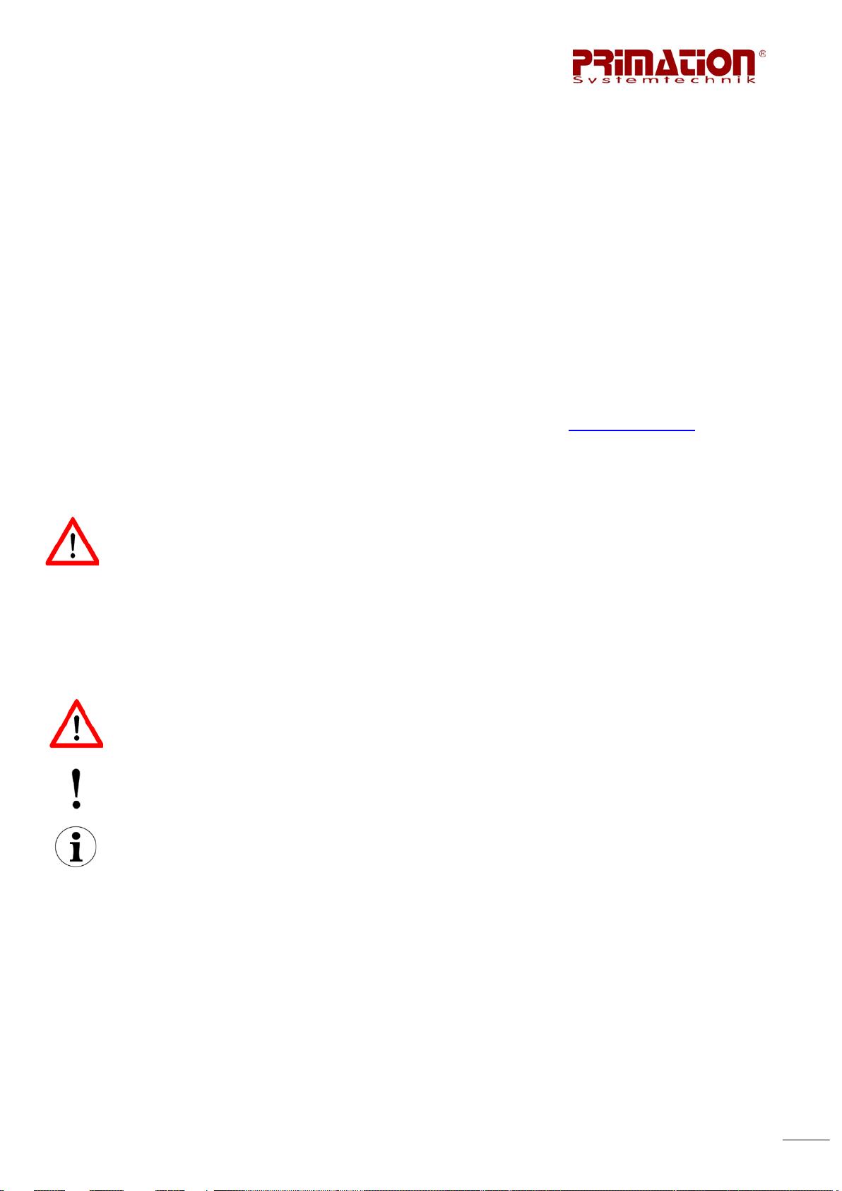
3.1. Informationen zum Aufbau des P-Ex WLAN
Durch die vier Befestigungsbohrungen an
den Ecken der Grundplatte wird die Montage
auf sicherem Untergrund erleichtert. Die
Bohrungen haben einen Durchmesser von
7mm.
Die PA Bohrungen der Erdungsschrauben
befinden sich jeweils an der Vorder- und
Hinterkante der P-Ex WLAN Grundplatte.
Klemmenanschlussraum unter Abdeckung
Kabelverschraubung M20 x 1,5 für Span-
nungsversorgung
Kabelverschraubung M20 x 1,5 für Datenlei-
tung
Ex e Anschlussraum:
Anschluss der Spannungsversorgung mittels
Klemmenblock.
Anschluss der Datenleitungen mittels LSA+
Modulklemmen. Bei PoE Einspeisung ebenfalls Anschluss der Spannungsversorgung.
7
LED blinkt
LED leuchtet
Power
---
Gerät ist gestartet
LAN LINK
Datenübertragung aktiv
Schnittstelle bereit
WLAN LINK
Datenübertragung aktiv
Schnittstelle bereit
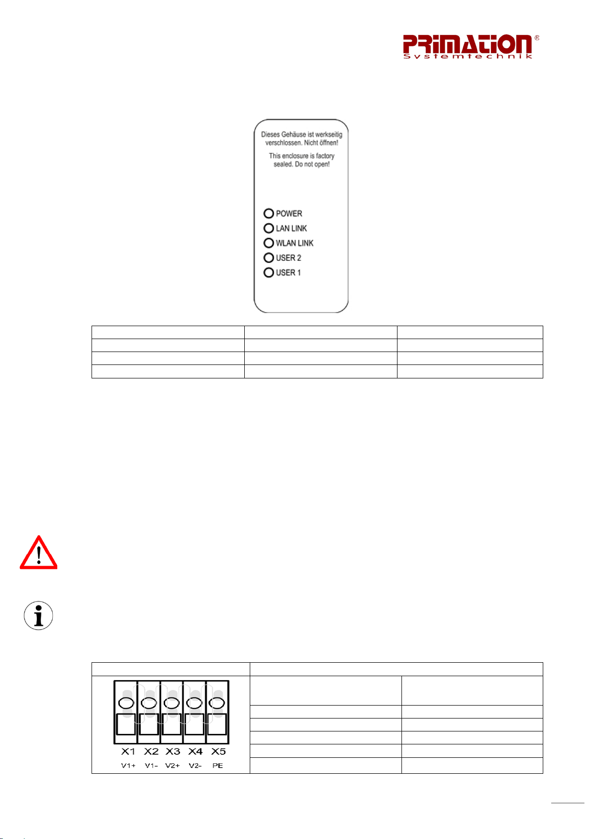
Klemmen X1 – X5 – Ex e
Belegung
V1+
X1
V1-
X2
V2+
X3
V2-
X4
PE
X5
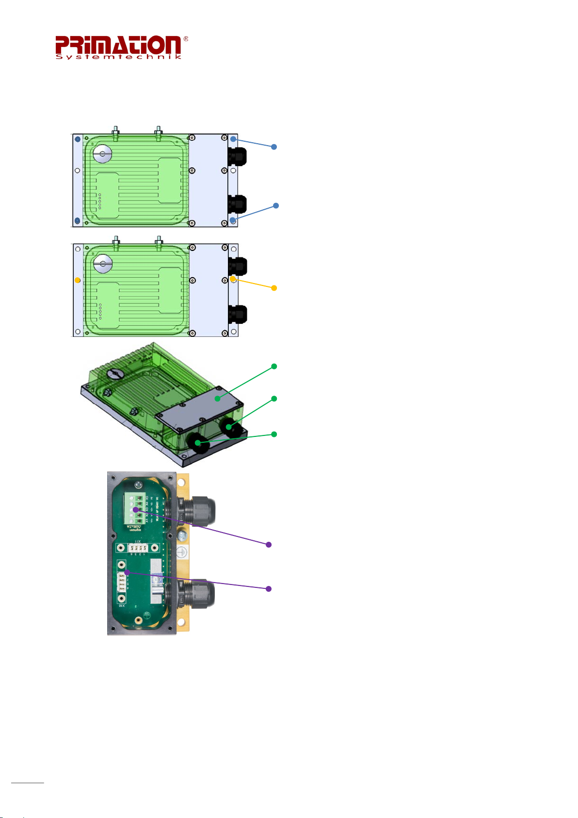
3.2. Bedeutung der Leuchtdioden
Alle Leuchtdioden sind erst nach Software-Einstellung und Reboot im korrekten Betrieb.
Die Leuchtdioden USER 1 und USER 2 sind in der Standardkonfiguration ohne Funktion.
Diese LEDs können im Menü mit einer Konfiguration belegt werden. Möglich ist hier zum
Beispiel die Anzeige der Feldstärke bei einer Punkt-zu-Punkt Verbindung von zwei WLAN
Geräten.
3.3. Pinbelegung P-Ex WLAN Versorgungsstromkreis X1-X5
Die Klemmenbelegung befindet sich unter der abschraubbaren Öffnung an der Frontseite
des P-Ex WLAN.
ACHTUNG!
Das Gehäuse nicht im explosionsgefährdeten Bereich öffnen!
Bevor das Gerät im explosionsgefährdeten Bereich in Betrieb genommen wird, muss sichergestellt sein, dass das Gehäuse wieder vollständig verschlossen und sachgemäß verschraubt wurde.
Änderungen an der Pinbelegung dürfen nur von eingewiesenem Fachpersonal durchgeführt
werden.
Pinbelegung des Versorgungsstromkreises DC: Klemmen X1-X5; Ex e – Erhöhte Sicherheit
Klemmen Bezeichnung Klemmen Nummer

8
LSA+ Modulklemme X10 –
Ex e
Klemmenbelegung
LSA+ Modulklemme X11 –
Ex e
Belegung
Betriebsspannung +18V bis +28V DC
Leiterquerschnitt flexibel -0,2 mm
Leiterquerschnitt starr -0,2 mm
2
– 1,3 mm2 / 24 AWG – 16AWG
2
– 1,3 mm2 / 24AWG – 16AWG
Es darf maximal 1 Leitung pro Klemme angeschlossen werden. Schrauben mit einem Drehmoment von 0,5Nm anziehen.
3.4. Pinbelegung P-Ex WLAN Versorgungs- (PoE) und Datenstromkreis
Pinbelegung des Versorgungsstromkreises DC (Power over Ethernet): an LSA+ Modulklemme X10
Bezeichnung Nummer
UB+ X10-4
UB+ X10-5
UB- X10-7
Betriebsspannung +18V bis +28V DC
UB- X10-8
Pinbelegung des Datenstromkreises an LSA+ Modulklemme: X11
Klemmen Bezeichnung Klemmen Nummer
Tx+ X11-1
Tx- X11-2
Rx+ X11-3
Rx- X11-6
Betriebsspannung 5V (± 1 0%)
Leitungsquerschnitt starr 0,4mm
2
– 0,64mm2 / 26AWG – 22AWG
Es darf maximal 1 Leitung pro Klemme angeschlossen werden. Das Kontaktieren der Kupferleiter erfolgt mit einem handelsüblichen LSA+ Auflegewerkzeug. Die Sicherungsbügel mit
einem Drehmoment von 1,2Nm anziehen.
9
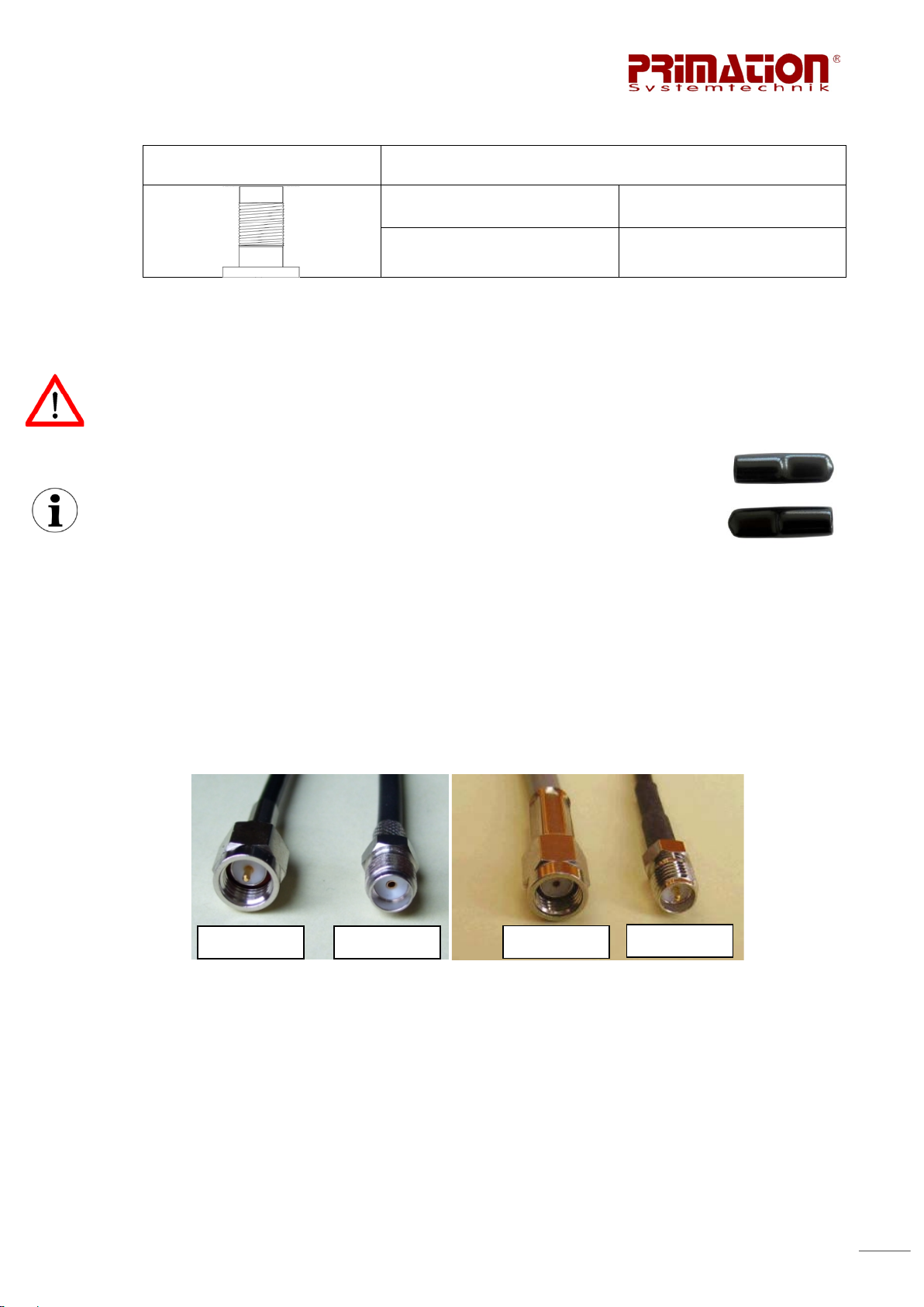
RP-SMA Steckverbinder –
Ex i
Buchse
Stecker
Stecker
Buchse
3.5. Sendesignal der RP-SMA Steckverbinder des P-Ex W LAN
Belegung
RP-SMA 1 Sendesignal 1
RP-SMA 2 Sendesignal 2
Die Frequenz beträgt 2,4GHz / 5GHz
Die Ausgangsleistung beträgt ≤ 312mW
Für den P-Ex WLAN dürfen ausschließlich die Antennen mit der Typnummer ANT-24/58-3/5I, ANT-24-7-I, ANT-24-8-O, ANT-24-2-O verwendet werden. Es müssen immer zwei Antennen des gleichen Typs verwendet werden.
3.6. Montage der Antennen des P-Ex W LAN
Bis zur fertigen Montage des P-Ex WLAN Access Points müssen die
Schutzkappen auf den RP-SMA Verbindern aufgesteckt bleiben.
Die Antennen des WLAN Access Point werden durch Verschrauben mit
den RP-SMA Steckern angeschlossen
Zu beachten ist, dass es sich bei dem P-Ex W L AN um RP-SMA Steckverbindungen handelt.
RP steht für Reverse Polarity, was bedeutet, dass Stecker und Buchse in der Verwendung
vertauscht sind. Das heißt die Buchse enthält den Dorn und der Stecker besitzt den Hohlraum in welchen der Dorn gesteckt wird. Dies ist bei der Beschaffung eventuell benötigter
Antennenkabel zu beachten.
SMA RP-SMA
10
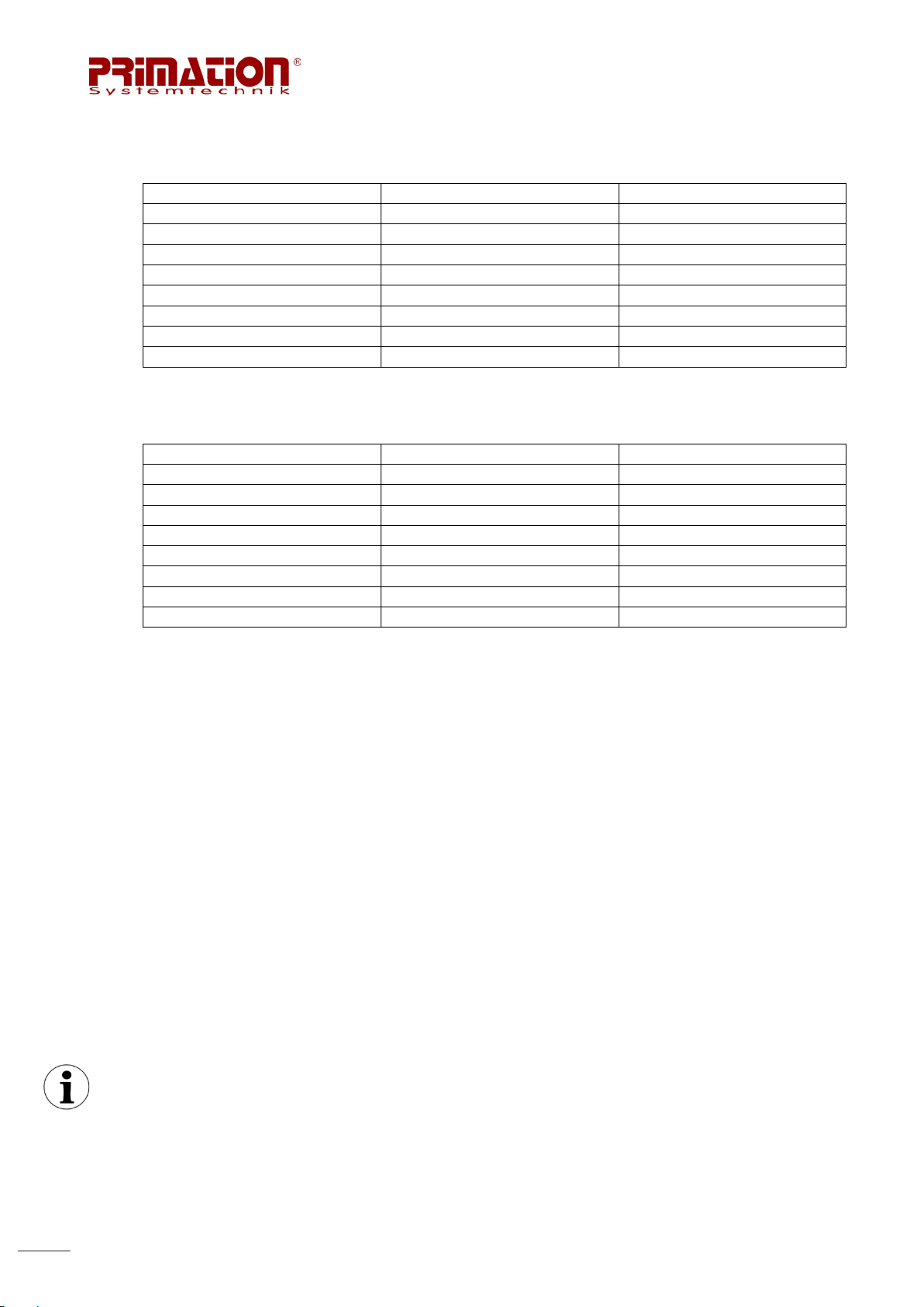
PIN LSA+ Modulklemme
Farbcode Cat-Kabel
Belegung 100BaseT
X10-4
WHT/BLU
UB+
X10-5
ORG
UB+
X10-7
WHT/BRN
UB-
X10-8
BRN
UB-
X11-1
WHT/GRN
Tx+
X11-2
GRN
Tx-
X11-3
WHT/ORG
Rx+
X11-6
BLU
Rx-
PIN LSA+ Modulklemme
Farbcode Cat-Kabel
Belegung 100BaseT
X10-4
BLU
UB+
X10-5
WHT/BLU
UB+
X10-7
WHT/BRN
UB-
X10-8
BRN
UB-
X11-1
WHT/ORG
Tx+
X11-2
ORG
Tx-
X11-3
WHT/GRN
Rx+
X11-6
GRN
Rx-
3.7. Farbcodes der Cat-Kabel/Ethernetkabel
Zuordnung der Cat-Kabel/Ethernetkabel und LSA+ Modulklemmen nach EIA/TIA T568A
Zuordnung der Cat-Kabel/Ethernetkabel und LSA+ Modulklemmen nach EIA/TIA T568B
4. Konfiguration des P-Ex WL AN
4.1. Verbindung zum P-Ex WLAN herstellen
Um den P-Ex WLAN an die jeweiligen Anforderungen anzupassen, muss dieser mit einem
PC Netzwerk verbunden werden. Die Anschlussbelegung des Konfigurationskabels kann bei
neueren PCs und Switchen sowohl nach EIA/TIA T568A als auch nach EIA/TIA T568B erfolgen (siehe Kapitel 3). Bei älteren PCs sowie Switchen ist die passende Anschlussbelegung
zu wählen.
4.2. Konfiguration mittels Web Interface
4.2.1. Standardeinstellungen des P-Ex WLAN
Standard IP Adresse: 192.168.100.1
SSID: P-Ex WLAN
WiFi Passwort: Prim@t1on
Benutzer: admin
Passwort: admin
Es ist darauf zu achten, dass sich der Rechner im selben IP-Netz befindet wie der P-Ex
WLAN. Sollte dies nicht möglich sein, ist unter Punkt 4.3 die Konfiguration mittels der Software Winbox beschrieben. Dort gibt es die Möglichkeit einer Verbindung auf MAC-Adressen
Basis.
11
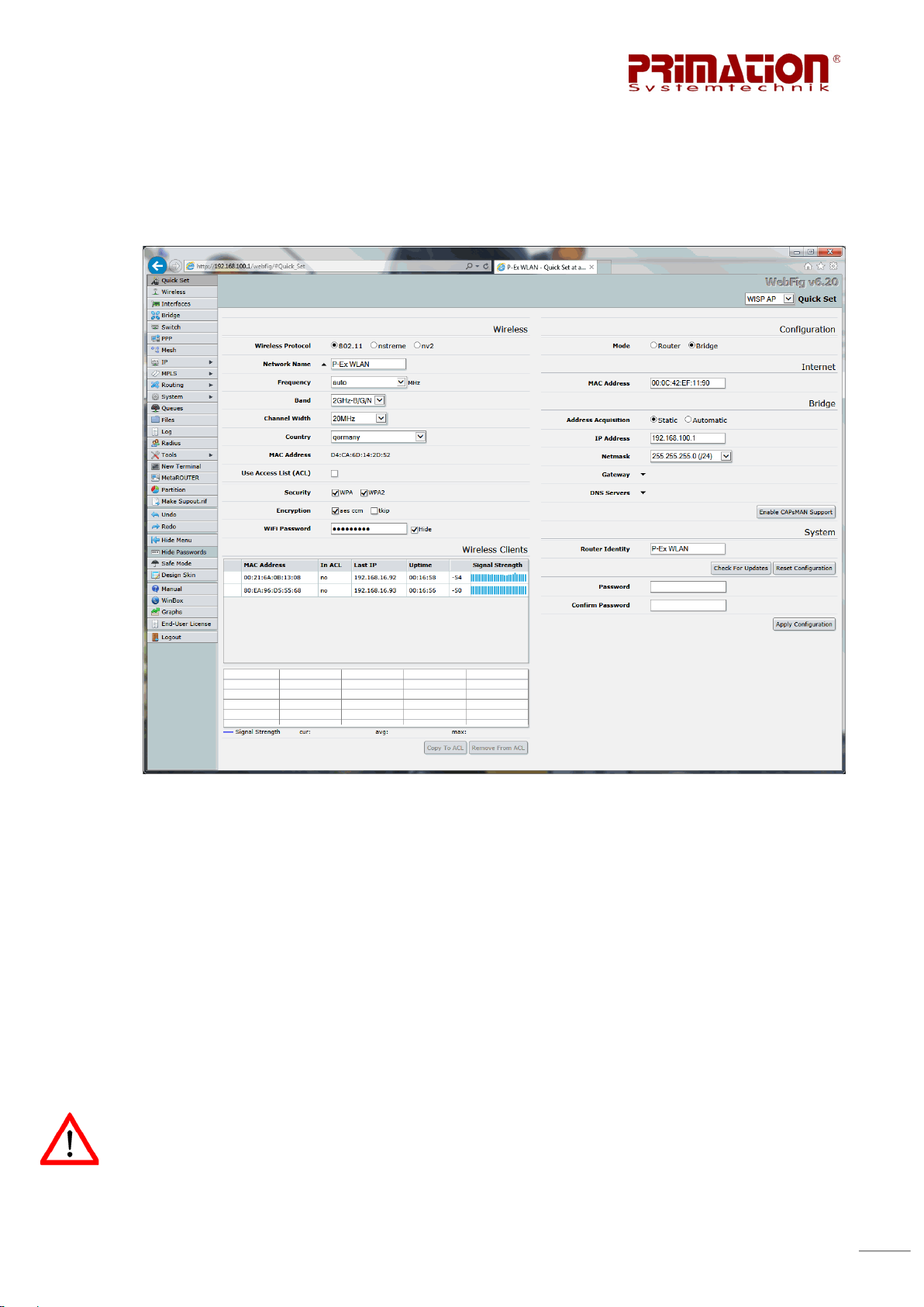
4.2.2. Quick Setup
Mittels Webbrowser kann die Verbindung zum P-Ex WLAN Access Point hergestellt werden.
Die IP Adresse des Gerätes muss hierzu in die Adresszeile des Br owsers eingegeben werden. Auf der ersten Seite des Konfigurationsmenüs können die Grundeinstellungen vorgenommen werden.
Der P-Ex WLA N ist ab Werk so konfiguriert, dass er als „Access Point – Bridge“ im 2GHzB/G/N Band arbeitet. Das Gerät stellt automatisch die beste Frequenz (Kanal) ein, die Ländereinstellungen für Deutschland und die Datenverschlüsselung ist aktiviert. Folgende Einstellungen können nun vorgenommen werden:
Quick Set:
Mit der Funktion Quick Set kann der P-Ex WLAN sehr schnell und unkompliziert in verschiedene Betriebsmodi geschalten werden. Alle wichtigen Einstellungen für den Betrieb können
dann auf einer Seite vorgenommen werden. Es stehen folgende Quick Set Einstellungen zur
Verfügung: CPE, Home AP, PTP Bridge und WISP AP.
Je nach Auswahl können dann die Daten für Network Name (SSID), IP Adressdaten und
WiFi Passwort eingegeben bzw. geändert werden.
Der P-Ex WLAN wird im Auslieferzustand immer in der Länderauswahl auf „Germany“ eingestellt. Der Betreiber hat dafür zu sorgen, dass gegebenenfalls eine Anpassung dieser Ländereinstellung erfolgt. Des Weiteren wurden unter dem Menüpunkt Wireless, Einstellungen
für die vom Betreiber bestellten Antennen vorgenommen. Diese sind nicht zu verändern!

12
Eine ausführliche Bedienungsanleitung für das Betriebssystem „RouterOS“ kann jederzeit
unter http://wiki.mikrotik.com
fig benötigte Kapitel in einem PDF zusammenzufassen und dauerhaft abzuspeichern.
heruntergeladen werden. Hier gibt es auch die Möglichkeit häu-
4.3. Konfiguration mit Winbox
Mit der Software Winbox kann der P-Ex WLAN von jedem Windows-Rechner aus konfiguriert
werden. Um die Software herunterzuladen kann entweder folgender Link genutzt werden:
http://www.mikrotik.com/download
P-Ex WLAN eingegeben wurde.
oder der Link im Br owserfenster wenn die IP Adresse des
Die Anwendung muss nicht installiert werden, das Ausführen der Anwendung reicht aus. Sobald Winbox gestartet wurde beginnt es automatisch alle verfügbaren Geräte mit dem RouterOS Betriebssystem anzuzeigen. Durch anklicken der IP Adresse wird der Eintrag automatisch in das „Connect To“ Feld übernommen. Mit dem Button Connect kann nun eine Verbindung aufgebaut werden.

13
Wenn die Verbindung über die IP Adresse nicht möglich ist, weil sich der P-Ex WLAN in einem anderen IP-Netz befindet, so kann mittels anklicken der MAC Adresse eine Verbindung
auf MAC Basis aufgebaut werden. Diese ist etwas langsamer als die Verbindung mittels IP
Adresse, reicht aber aus um die Grundeinstellungen am P-Ex WLAN vorzunehmen und diesen ins korrekte IP-Netz zu bringen. Anschließend kann die Verbindung jederzeit über IP erfolgen.

14
Frequenzbereich GHz
Antennengewinn dBi
Dualband Aufsteckantenne
Aufsteckantenne
Rundstrahlantenne
Rundstrahlantenne IP68
Verlängerungs-
cker
Verlängerungs-
cker
Verlängerungs-
N-Stecker
PoE Injektor
PoE Injektor
---
---
---
---
CAB-OPENRJ45-CONFIG
Konfigurationskabel
Eine Anleitung in der die Möglichkeiten der Winbox detailliert erläutert werden ist unter
http://wiki.mikrotik.com/wiki/Winbox
Die Basiseinstellungen des P -Ex WLAN erfolgen ebenfalls mittels der Quick Sets wie unter
4.2.2 beschrieben.
5. Zubehör P-Ex WLAN
5.1. Übersicht Zubehör
einsehbar.
Typ Bezeichnung
ANT-24/58-3/5-I
ANT-24-7-I
ANT-24-8-O
ANT-24-2-O
CAB-RSMA/FRSMA-M-3
CAB-RSMA/FRSMA/M-5
CAB-RSMA-/MN/M-5
kabel 3m RPSMA Buchse /
RP-SMA Ste-
kabel 5m RPSMA Buchse /
RP-SMA Ste-
kabel 5m RPSMA Buchse /
Länge Einsatzbereich
2,4/5 3/5 22cm Innen
2,4 7 30cm Innen
2,4 8 64cm Außen
2,4 2 9,2cm IP68
--- --- 3m ---
--- --- 5m ---
--- --- 5m ---
5.2. Beschreibung des Zubehörs
--- --- 1,5m ---
• Dualband Aufsteckantenne für den Innenbereich (ANT-24/58-3/5-I)
Dualband Aufsteckantennen mit neigbarem Fuß zwischen Null und 90°. Antennengewinn 3
dBi bei 2,4 GHz und 5 dBi bei 5,8 GHz bei einer Länge von 22 cm. Antennen ohne Richtwirkung für den Innenbereich. Befestigung direkt am Access Point oder über ein Verlängerungskabel und MIMO-Antennenständer auf dem Schaltschrank möglich.
• Aufsteckantenne für den Innenbereich (ANT-24-7-I)
2,4 GHz Aufsteckantennen mit neigbarem Fuß zwischen Null und 90°. Antennengewinn 7
dBi bei 2,4 GHz bei einer Länge von 30 cm. Antennen ohne Richtwirkung für den Innenbereich. Befestigung direkt am Access Point oder über Verlängerungskabel und MIMOAntennenständer auf dem Schaltschrank möglich.

15
• Rundstrahl Antenne für den Außenbereich (ANT-24-8-O)
Vertikalrundstrahler für den 2,4 GHz Bereich mit 8 dBi Antennengewinn und einer Läng e von
64 cm. Wetterfeste Ausführung für den Außenbereich, aber auch ideal für die Versorgung
von Innenräumen, z.B. im Treppenhaus. Der Strahler ist gleichspannungsmäßig geerdet um
statische Aufladungen zu verhindern. Die Antenne wird über ein Verlängerungskabel (CABRSMA-/M-N/M-5) am Access Point angeschlossen.
• Rundstrahl Antenne IP68 (ANT-24-2-O)
Wasserdichte kurze Aufsteckantenne für den 2,4 GHz Bereich mit 2 dBi Antennengewinn
und einer Länge von 9,2 cm. Die Antenne wird über ein 150 cm langes Verlängerungskabel
am Access Point angeschlossen.
• Verlängerungskabel von RP-SMA Buchse auf RP-SMA Stecker 3 Meter (CAB-RSMA/FRSMA-M-3)
Zum Anschluss von Antennen mit RP-SMA-Buchse an Access Points mit RP-SMA-Stecker
von 3 Meter Kabellänge aus dämpfungsarmen H-155 Kabel. Geeignet für folgende Antennen-Typen: ANT-24/58-3/5-I und ANT-24-7-I.
• Verlängerungskabel von RP-SMA Buchse auf RP-SMA Stecker 5 Meter (CAB-RSMA/FRSMA/M-5)
Zum Anschluss von Antennen mit RP-SMA-Buc hse am Access Point mit RP-SMA-Stecker
von 5 Meter Kabellänge aus dämpfungsarmen H-155 Kabel. Geeignet für folgende Antennen-Typen: ANT-24/58-3/5-I und ANT-24-7-I.
• Verlängerungskabel von RP-SMA Buchse auf N-Stecker (CAB-RSMA-/M-N/M-5)
Zum Anschluss von Antennen mit N-Buchse am Access Point mit RP-SMA-Stecker von 5
Meter Kabellänge aus dämpfungsarmen H-155 Kabel. Geeignet für folgende AntennenTypen: ANT-24-8-O.
• PoE-Injektor
Ermöglicht den Anschluss der Versorgungsspannung (24V) über das Ethernetkabel. Eine
Redundante Spannungsversorgung über das Ethernetkabel ist mit diesem PoE-Injektor m öglich.
• Konfigurationskabel RJ45 auf offenes Ende (CAB-OPEN-RJ45-CONFIG)
Ermöglicht den Anschluss zur Konfiguration des P-Ex WLAN
an einen PC.

16
6. Anhang
6.1. EG-Baumusterprüfbescheinigung

17

18
7. Kontakt
PRIMATION Systemtechnik GmbH & Co. KG
Bretonischer Ring 13
85630 Grasbrunn
Deutschalnd
Tel.: +49 (0)89 / 46 26 0 - 0
Fax: +49 (0)89 / 46 26 0 - 210
Mail: info@primation.de
Web: http://www.primation.de

User manual
WLAN access point
Type P-Ex WLAN-DC-A
Type P-Ex WLAN-DC-S
ATEX Version
Zone 1/21/M2
Version: 1.2
Drafted: 08/02/2017
Subject to technical changes!
Contents Page
German 1-18
English 19-37
PRIMATION Systemtechnik Tel: +49 (0) 89 46 26 0 - 0
GmbH & Co. KG Fax: +49 (0) 89 46 26 0 - 210
Bretonischer Ring 13 Email: info@primation.de
85630 Grasbrunn Website: http://www.primation.de
Germany


Contents
1. Important instructions for use ................................................................................................... 20
1.1. Instructions for us e ........................................................................................................... 20
1.2. Pictograms and safety guidelines...................................................................................... 20
1.3. General warnings .............................................................................................................. 21
2. Product information .................................................................................................................. 23
2.1. Manufacturer .................................................................................................................... 23
2.2. Explosion protection ......................................................................................................... 23
2.3. Technical data .................................................................................................................. 23
2.4. Type numbers ................................................................................................................... 24
2.5. Use ................................................................................................................................... 24
3. Operating the P-Ex WLAN access point ................................................................................... 25
3.1. Assembly information for the P-Ex WLAN ......................................................................... 25
3.2. LED signals ...................................................................................................................... 26
3.3. Pin assignment for the P-Ex WLAN power circuit X1-X5 ................................................... 26
3.4. Pin assignment P-Ex WLAN power supply (PoE) and data stream circuit ......................... 27
3.5. Transmission signal of RP-SMA plug connector of the P-Ex WLAN .................................. 28
3.6. Assembling the P-Ex WLAN's antennas ........................................................................... 28
3.7. Color coding of the cat-cable/ethernet cable ..................................................................... 29
4. Configuration of the P-Ex WLAN .............................................................................................. 29
4.1. Connecting to the P-Ex WLAN .......................................................................................... 29
4.2. Configuration via web interface ......................................................................................... 29
4.3. Configuration via Winbox .................................................................................................. 31
5. P-Ex WLAN accessories .......................................................................................................... 33
5.1. Accessories overview ....................................................................................................... 33
5.2. Description of accessories ................................................................................................ 33
6. Attachment .............................................................................................................................. 35
6.1. EC-type examination certificate ........................................................................................ 35
7. Contact .................................................................................................................................... 37

20
1. Important instruc ti ons f or us e
1.1. Instructions for use
Please read this manual through carefully before using the device.
This user manual contains information about key functions and safety precautions. If
they are not observed, no guarantee is given that the device can be used in potentially
explosive environments, for which it is intended.
The instructions in this manual must be observed when operating and using the product.
We do not guarantee the manual is up-to-date. PRIMATION Systemtechnik GmbH & Co. KG
reserves the right to amend this document.
Ensure that you are using the most up to dat e version of this manual before using t he prod-
uct. You can email us at info@primation.de
of the PRIMA TI ON team.
Images contained in this manual are for illustrative purposes and therefore may differ from
the actual product.
to be sent the latest version or to ask a member
The device may not be adapted in any way that has not received prior approval from PRIMATION Systemtechnik GmbH & Co. KG.
Improper use of the device may void the user's authority to operate it in potentially explosive
environments.
Not following the guidelines of use will also void the warranty on the product.
1.2. Pictograms and safety guidelines
This signals danger of injury or death if codes of conduct have not been complied with.
Please follow all safety precautions and warnings that are marked with this pictogram.
Indicates a potentially dangerous situation that may lead to material damage if no evasive
action is taken.
Indicates useful tips, recommendations and information for efficient, environmentally friendly
and trouble free operation.

21
1.3. General warnings
1.3.1. Warnings
• The device may only be operated when fully assembled.
• Do not wipe with a dry cloth or clean the device in a potentially explosive environment!
• The device must be immediately shut down if you have reason to suspect it cannot run any-
more without causing harm or endangering people (e.g. if it has been exposed to water, fluids or a temperature outside of the specified range).
• Legal provisions or directives regarding safety at work, health and safety or environmental
protection must be observed (e.g. the Industrial Safety Regulation)
• Do not open up the device.
• Do not make any changes to the device. Do not exchange or replace any of the device's
parts. If non-specified parts are used, the explosion-protecting function is no longer guar anteed.
• If the device suffers any damage to its housing, remove it immediately from the potentially
explosive environment.
• In accordance with IEC 60079-17 and IEC 60079-19, the operator of electrical devices in po-
tentially explosive environments is required to get the devices tested by a specialist electrician, to check whether it is in good working condition.
• Do not insert anything into the P-Ex WLAN access point's openings or housing. Openings on
the device may not be plugged or covered.
• The device and accessories must be disposed of correctly and in accordance with any legal
requirements by an authorized company.
1.3.2. Installation instructions
• For electrical devices, take note of the applicable installation and operating regulations (e.g.
RL 94/9/EG, RL 99/92/EG and nationally applicable directives, IEC 60079-14 and the DIN
VDE 0100 standard).
• The operator is responsible for carrying out the required maintenance and upkeep of the de-
vice in potentially explosive environments.
• The installation of the WLAN access point should only be carried out in ex-environments of
device groups I and II as well as device categories M2, 2G and 2D.
• The operator is responsible for ensuring that the P-Ex WLAN is running the correct settings
for the right country and that it doesn't exceed the permitted transmission power.
• When installed outside safety measures for lightning protection have to be taken.
1.3.3. Instructions regarding the antennas
• Antennas and antenna cables must be cleaned with a damp cloth.
• Antennas and antenna cables must not be exposed to radiation.
• Only ANT-24/58-3/5I, ANT-27-7-I, ANT-24-8-O, ANT-24-2-O type antennas may be used
with the P-Ex WLAN access point.
• Always use two antennas of the same type!
1.3.4. Maintenance
Provided the assembly instructions and the environmental requirements are observed and
the device is correctly used, ongoing maintenance is not required.

22
1.3.5. Inspection
The operator must have any electrical device that is intended for use in potentially explosive
environments tested by a specialized electrician to check it is in good working order (IEC
60079-17 and IEC 60079-19).
1.3.6. Repairs
Repairs may only be carried out by the manufacturer or any person who has been trained
and tasked to carry them out.
The device is sealed by the manufacturer. It should only be opened by a specialist at
the factory.
1.3.7. Operation
Before operating the device, check whether all required components are present and that the
software was correctly installed.

23
2. Product information
2.1. Manufacturer
PRIMATION Systemtechnik GmbH & Co. KG
Bretonischer Ring 13
85630 Grasbrunn
Germany
2.1.1. Device types
P-Ex WLAN-DC-A
P-Ex WLAN-DC-S
2.2. Explosion protection
I M2 Ex eb qb [ib] I
I M2 Ex e q [ib] I Mb
II 2G Ex eb qb [ib ] IIC T4
II 2G Ex e q [ib] IIC T4 Gb
II 2D Ex tb IIIC T135°C
II 2D Ex tb IIIC T135°C Db
2.2.1. Operating temperature
-20°C ≤ Ta ≤ +60°C
2.2.2. Protective housing type
IP64
2.2.3. Test certificate
IBExU14ATEX1114
2.3. Technical data
2.3.1. Power supply
DC, redundant
alternative: Power over Ethernet (PoE; not IEEE 802.3af)
Nominal voltage: +18V to +28V DC
2.3.2. Interfaces and connectors
Supply circuit (DC) X1, X2, X3, X4
Supply circuit DC (Power X10-4, X10-5
over Ethernet) to LSA+ module clamps X10-7, X10-8
Potential equalizer (PE) X5
Data stream circuits X11-1, X11-2, X11-3, X11-6
Sending stream circuit via RP-SMA Antennas 1, 2
plug connectors
Max. input current at 24V I
Max. power input P
≤ 460 mA
max
≤ 11 W
max

24
Max. electromagnetic P
≤ 312 mW (25dBm)
em. max
output
Supply circuit to X10-4 UB+
LSA+ module clamps X10-5 UB+
Ex e – improved safety X10-7 UB X10-8 UB-
Data stream circuit via X11-1 Tx+
LSA+ module clamps X11-2 Tx Ex e – improved security X11-3 Rx+
X11-6 Rx-
Operating circuit power +18V to +28V DC
Operating data stream circuit power 5V (±10%) DC
Data stream circuit interface (radio) Plug connector type: RP-SMA
Frequency 2.4GHz / 5GHz
Antennas Only use Antennas ANT-24/58-3/5-I, ANT-24-7-I, ANT-24-8-O and
ANT-24-2-O.
WLAN range Indoors ≤ 300m
(depending on the antenna) Outdoors ≤ 50km
Range for copper cat. 5 100m
Dimensions 150mm x 270mm x 60mm (HxWxD)
Weight Type P-Ex WLAN-DC-A 3.3kg (aluminum)
Type P-Ex WLAN-DC-S 4.5kg (V2A stainless steel)
Atmospheric temperature -20°C to +60°C
2.4. Type numbers
P-Ex WLAN-DC-A Aluminum housing
P-Ex WLAN-DC-S V2A stainless steel housing
2.5. Use
The WLAN access point enables you to connect wireless devices to a cable network or to
connect two networks in potentially explosive environments.
The stationary device enables the transfer of electronic and electromagnetic data signals.
The P-Ex WLAN-DC-X can be deployed in the ex-environment of device category II, gas and
dust, in its aluminum housing. For use in device category I (firedamp protection), an identical
housing made of stainless steel with the corresponding permitted screw-type cable connectors.

25
3. Operating the P-Ex WLAN access point
3.1. Assembly information for the P-Ex WLAN
The bottom plate has four drilled holes, one
on each corner, which facilitate securely
mounting the device. The holes have a diameter of 7mm.
The PA drill holes for the earthing screws are
at the front and back edges of the P-Ex
WLAN bottom plate.
Screw terminal connection under cover
M20 x 1.5 cable screw connection for power
supply
M20 x 1.5 cable screw connection for data
stream
Ex e connector inputs:
Power supply connector via terminal block.
Data cable connector via LSA+ module
clamps. PoE input also has power connector.

26
LED flashing
LED on
Power
---
Device has booted
LAN LINK
Data transfer is active
Interface ready
WLAN LINK
Data transfer is active
Interface ready
Clamps X1 - X5 - Ex e
Assignment
V1+
X1
V1-
X2
V2+
X3
V2-
X4
PE
X5
3.2. LED signals
All LEDs only run correctly once the software has been correc tly set up and the device has
been rebooted.
The USER 1 and USER 2 LEDs have no preset function. These LEDs can be confi gured to
give a signal via the menu. As an example, they can be made to indicate the reception signal
strength in the point-to-point connection between two WLAN devices.
3.3. Pin assignment for the P-Ex WLAN power circuit X1-X5
The connection screw clamp assignment is beneath the opening on the front of the P-Ex
WLAN, which can be unscrewed and removed.
WARNING!
Do not open the device in a potentially explosive environment!
Before using the device in a potentially explosive environment, ensure that the housing has
been re-assembled and screwed into place correctly.
Changes to the pin assignment may only be carried out by a specialist, who is instructed to
do so.
Pin assignment for the DC power supply circuit: Clamps XI-X5, Ex e - improved security
Clamps description Clamps number

27
LSA+ X10 module clamp Ex e
Assignment
LSA+ X11 module clamp –
Ex e
Assignment
Operating voltage +18V to +28V DC
Conductor cross-section flexible -0.2 mm
Conductor cross-section rigid -0.2 mm
2
– 1.3 mm2 / 24 AWG – 16AWG
2
– 1.3 mm2 / 24AWG – 16AWG
A maximum of 1 conductor per clamp may be connected. Tighten the screws with a torque of
0.5Nm.
3.4. Pin assignment P-Ex WLAN power supply (PoE) and data stream circuit
Pin assignment of the DC power supply circuit (power over ethernet): to LSA+ X10 module
clamp
Clamps description Clamps number
UB+ X10-4
UB+ X10-5
UB- X10-7
Operating voltage +18V to +28V DC
UB- X10-8
Pin assignment of the data stream circuit to LSA+ module clamp: X11
Clamps description Clamps number
Tx+ X11-1
Tx- X11-2
Rx+ X11-3
Rx- X11-6
Operating voltage 5V (± 10%)
Conductor cross-section rigid 0.4mm
2
– 0.64mm2 / 26AWG – 22AWG
A maximum of 1 conductor per clamp may be connected. The copper conductors are connected with a standard LSA+ punch down tool. Tighten the safety catch with a torque of
1.2Nm.

28
RP-SMA plug connector Ex i
Socket
Plug
Plug
Socket
3.5. Transmission signal of RP-SMA plug connector of the P-Ex WLAN
Assignment
RP-SMA 1 Transmission signal 1
RP-SMA 2 Transmission signal 2
The frequency is 2.4GHz/5GHz
The output level is ≤ 312mW
Only ANT-24/58-3/5-I, ANT-24-7-I, ANT-24-8-O, ANT-24-2-O type antennas may be used
with the P-Ex WLAN. Always use two antennas of the same type.
3.6. Assembling the P-Ex WLAN's antennas
Keep the protective caps on the RP-SMA connectors until the P-Ex W LAN
access point is fully assembled.
The antennas of the WLAN access point are attached by screwing the
ends into the RP-SMA sockets
Make sure the P-Ex WLAN is equipped with RP-SMA sockets. RP stands for reverse polarity, meaning that the plug and socket are swapped. So the sock et contains the male pin and
the plug has the female socket that goes over it. Please note this when acquiring antenna
cables.
SMA RP-SMA

29
PIN LSA+ module clamp
Cat-cable color code
100BaseT assignment
X10-4
WHT/BLU
UB+
X10-5
ORG
UB+
X10-7
WHT/BRN
UB-
X10-8
BRN
UB-
X11-1
WHT/GRN
Tx+
X11-2
GRN
Tx-
X11-3
WHT/ORG
Rx+
X11-6
BLU
Rx-
PIN LSA+ module clamp
Cat-cable color code
100BaseT assignment
X10-4
BLU
UB+
X10-5
WHT/BLU
UB+
X10-7
WHT/BRN
UB-
X10-8
BRN
UB-
X11-1
WHT/ORG
Tx+
X11-2
ORG
Tx-
X11-3
WHT/GRN
Rx+
X11-6
GRN
Rx-
3.7. Color coding of the cat-cable/ethernet cable
Allocation of the cat-cable/ethernet cable and LSA+ module clamps according to EIA/TIA
T568A
Allocation of the cat-cable/ethernet cable and LSA+ module clamps according to EIA/TIA
T568B
4. Configuration of the P-Ex WLAN
4.1. Connecting to the P-Ex WLAN
To configure the P-Ex WLAN to meet the requirements it needs to be connected to a PC
network. The pin assignment for the configuration cable can be carried out on newer computers or by switching in accordance with EIA/TIA T568 as well as EIA/TIA T568B (see chapter 3). For older PCs and when switching, the right pin assignment needs to be configured.
4.2. Configuration via web interface
4.2.1. Standard settings of the P-Ex WLAN
Standard IP address: 192.168.100.1
SSID: P-Ex WLAN
WiFi password: Prim@t1on
User: admin
password: admin
Please ensure that the computer is connected to the same network as the P-Ex WLAN. If this
is not possible, please see how to set up the configuration via 'Winbox' in chapter 4.3. This
allows you to set up a connection via MAC addresses.

30
4.2.2. Quick Setup
You can set up a connection with the P-Ex WLAN access point via a web browser. To do
this, copy the device's IP address into the browser address bar. On the first page of the configuration menu you can set up the basic settings.
As per the factory settings, the P-Ex WLAN shows up as "Access Point - Bridge" at a frequency of 2GHz-B/G/N. The device automatically chooses the best frequency (channel),
runs the country settings for Germany and activates data encryption. You can now change to
following settings :
Quick Set:
The Quick Set function allows you to quickly and simply switch the P-Ex W LAN between different operating modes. Through this, you can change all the m ost important operating settings on one page. This function offers the following Q uick Set sett ings : CPE, Home AP, PTP
Bridge and WISP AP.
Depending on what you select, the network name (SSID), IP address and WiFi password can
all be chosen or changed.
The factory settings of each P-Ex WLAN on delivery are selected for "Germany". The operator of the device is responsible for changing these settings to whichever other country, if
necessary. Furthermore, if you select the menu option 'Wireless', you will see the settings
have been configured according to the antennas ordered by the operator. Do not change
these!

31
A detailed instruction manual for the operating system "RouterOS" can be downloaded from
http://wiki.mikrotik.com
at any time. When visiting this website, you also have the option of
downloading any really useful chapters as a PDF, which you can then save on your computer for future reference.
4.3. Configuration via Winbox
Winbox allows the P-Ex WLAN to be configured from any windows-based computer. To
download the software, you can either click on this link: http://www.mikrotik.com/download
on the link that appears in the browser window once the P-Ex WLAN's IP address has been
put into the browser address bar.
or
The application does not need to be installed, it only needs to be run. As soon as Winbox
loads, it automatically starts to display all available devices using the RouterOS operating
system. When you click on an IP address it is automatically copied into the "Connect To"
field. Click "Connect" to establish a connection.

32
If the connection cannot be made via the IP address because the P-Ex WLAN is connected
to a different IP network, you can click on the MAC address to use the MAC method to set up
a connection. This is somewhat slower than the connection via IP address but is sufficient to
configure the P-Ex WLAN's basic settings and transfer these into the correct IP network. Finally, the connection can be established via IP.

33
Frequencyrange in GHz
Antenna
gain in dBi
Operating
range
Dualband screw-in antenna
ANT-24-7-I
Screw-in antenna
2.4
7
30cm
Indoors
Omni-directional antenna
Omni-directional antenna IP68
3m extension cable for
RP-SMA plug
5m extension cable for
RP-SMA plug
5m extension cable for
plug
PoE Injektor
PoE injector
---
---
---
---
CAB-OPEN-RJ45CONFIG
To see a guide on all the different functions Winbox offers, go to
http://wiki.mikrotik.com/wiki/Winbox
The basic settings of the P-Ex WLAN can be configured via the Quick Set function as described in 4.2.2.
5. P-Ex WLAN accessories
5.1. Accessories overview
.
Type Description
ANT-24/58-3/5-I
ANT-24-8-O
ANT-24-2-O
CAB-RSMA/F-
RSMA-M-3
CAB-RSMA/F-
RSMA/M-5
CAB-RSMA-/M-
N/M-5
the RP-SMA socket /
the RP-SMA socket /
the RP-SMA socket / N
Configuration cable --- --- 1.5m ---
Length
2.4/5 3/5 22cm Indoors
2.4 8 64cm Outdoors
2.4 2 9.2cm IP68
--- --- 3m ---
--- --- 5m ---
--- --- 5m ---
5.2. Description of accessories
• Dualband indoor screw-in antenna (ANT-24/58-3/5-I)
Dualband screw-in antenna with a zero to 90° adjust able base. Antenna gain of 3 dBi at 2.4
GHz and 5 dBi at 5.8 GHz with a length of 22 cm. Non-directional antennas for indoor use.
These can either be attached directly to the access point or via an extension cable using an
MIMO antenna stand, configurable on the control panel.
• Screw-in antenna for indoor use (ANT-24-7-I)
2.4 GHz screw-in antennas with a zero to 90° adjustable base. Antenna gain of 7 dBi at 2.4
GHz with a length of 30 cm. Non-directional antennas for indoor use. Attachable directly to
the access point or via an extension cable using MIMO antenna stand, configurable on the
control panel.
• Omni-directional antennas for outdoor use (ANT-24-8-O)
Omni-directional for 2.4 GHz frequency range with an antenna gain of 8 dBi and a length of
64 cm. W eather-proof version for outdoor use, which is also perfectly suited for use in indoor
spaces such as a staircase. It is earthed with a dir ect current, preventing static build-u p. The
antenna is attached to the access point via an extension cable (CAB-RSMA-/M-N/M-5).

34
• Omni-directional antenna IP68 (ANT-24-2-O)
Water-proof, short, screw-in antenna for the 2.4 GHz frequency range with an antenna gain
of 2 dBi and a length of 9.2cm. The antenna is connected to the access point via a 150 cm
extension cable.
• 3 meter extension cable (CAB-RSMA/F-RSMA-M-3) from the RP-SMA socket to RPSMA plug
Connects the antenna's RP-SMA sockets to the RP-SMA plug of the access point via a 3
meter extension cable made of low-loss H-155 cable. Designed for use with the following antennas: ANT-24/58-3/5-I and ANT-24-7-I.
• 5 meter extension cable (CAB-RSMA/F-RSMA/M-5) from the RP-SMA socket to RPSMA plug
Connects the antenna's RP-SMA sockets to the RP-SMA plug of the access point via a 5
meter extension cable made of low-loss H-155 cable. Designed for use with the following antennas: ANT-24/58-3/5-I and ANT-24-7-I X.
• Extension cable (CAB-RSMA-/M-N/M-5) from the RP-SMA socket to N plug
Connects the antenna's N-sockets to the RP-SMA plug of the access point via a 5 meter extension cable made of low-loss H-155 cable. Designed for use with the following antenna:
ANT-24-8-O.
• PoE injector
Allows you to connect the power supply (24V) via the ether net c able. The PoE injec t or allo ws
you to connect the redundant power supply via the ethernet cable.
• Open-ended RJ45 configuration cable (CAB-OPEN-RJ45-CONFIG)
Enables you to connect to and configure the P-Ex WLAN via a PC.

35
6. Attachment
6.1. EC-type examination certificate

36

37
7. Contact
PRIMATION Systemtechnik GmbH & Co. KG
Bretonischer Ring 13
85630 Grasbrunn
Germany
Tel: +49 (0) 89 / 46 26 0
Fax: +49 (0) 89 / 46 26 0 - 210
Email: info@primation.de
Website: http://www.primation.de
 Loading...