

Primation P-Ex OTR opis 100, P-Ex OTR opis 1000, P-Ex OTR opis MC, P-Ex OTR opis 100-SM15, P-Ex OTR opis 1000-SM10 User Manual

Bedienungsanleitung
Abb. ähnlich 1
Optischer Transceiver
Typ P-Ex OTR opis 100
Typ P-Ex OTR opis 1000
Typ P-Ex OTR opis MC*
*alle Hinweise gelten auch für die Modelle
P-Ex OTR opis 100-SM15
P-Ex OTR opis 1000-SM10
Version: 3.10
Dokumenten-Nr. EX-11-200002
Stand: 19.12.2014
Technische Änderungen vorbehalten!
Inhalt Seite
Deutsch 1 - 16
Englisch 17 - 29
PRIMATION Systemtechnik Tel.: +49 (0)89 46 26 0 - 0
GmbH & Co. KG Fax: +49 (0)89 46 26 0 - 210
Bretonischer Ring 13 Mail: info@primation.de
85630 Grasbrunn Web: http://www.primation.de
Deutschland


Vor Inbetriebnahme
Bitte lesen Si e die Bedienungsanleitung vollständig und sorgfältig durch!
Zielgruppe:
Erfahrene Fachkräfte unter Einhaltung der Richtlinien 99/92/EG, IEC 60079-19 sowie EN
60079-17.
Bitte beachten:
Dieses Benutzerhandbuch beinhaltet wichtige Hinweise, Sicherheitsvorschriften und Pr üfbescheinigungen, die für eine einwandfreie Funktionsweise bei der Bedienung und Handhabung der Optischen Transceiver erforderlich sind. Werden die Hinweise und Sicherheitsvorschriften nicht beachtet, ist die bestimmungsgemäße Verwendung nicht gewährleistet.
Änderungen an den Geräten, die nicht ausdrücklich durch PRIMATION Systemtechnik
GmbH & Co. KG (PRIMATION) genehmigt wurden, führen zum Erlöschen der Betriebserlaubnis für das betreffende Gerät. Eine Nichteinhaltung schließt Gewährleistungsansprüche
aus. Die Gewährleistung erlischt, wenn Schäden an dem Produkt eintreten, die auf unsachgemäße Behandlung, übermäßige Beanspruchung, ungenügende Instandhaltung, anormale
Betriebsbedingungen sowie auf Transportschäden zurückzuführen sind. Natürlicher Verschleiß ist ebenfalls von der Gewährleistung ausgeschlossen.
PRIMATION behält sich vor, inhaltliche Änderungen an diesem Dokument ohne Ankündigung vorzunehmen. Die Richtigkeit der Informationen ist ohne Gewähr. Im Zweifelsfall sind
die deutschen Sicherheitshinweise gültig, da Übersetzungs- und Druckfehlern nicht ausgeschlossen werden können. Im Rechtsfall gelten ergänzend die "Allgemeinen Geschäftsbedingungen" der PRIMATION.
Die jeweils aktuelle Version der Datenblätter, Handbücher, Zertifikate und der EGKonformitätserklärung können auf der Produktseite "ATEX" unter www.primation.de heruntergeladen oder direkt bei der PRIMATION angefordert werden.
Dokumentation
Die Unterlagen sind in Deutsch und Englisch verfügbar.
Besuchen Sie unsere Webseite http://www.primation.de und informieren Sie sich über Ihr
spezielles Produkt.


Piktogramme und Sicherheitshinweise
Signalisiert Verletzungs- oder Lebensgefahr, sofern bestimmte Verhaltensregeln
missachtet werden. Befolgen Sie bitte alle Sicherheitsvorkehrungen, die mit diesem
Piktogramm gekennzeichnet sind.
Kennzeichnet eine möglicherweise gefährliche Situation, die zu Sachschäden führen kann, wenn sie nicht gemieden wird.
Kennzeichnet nützliche Tipps, Empfehlungen und Informationen für einen effizienten, umweltgerechten und störungsfreien Betrieb.

Inhalt
1 Produktbeschreibung ..................................................................................................... 1
1.1 Allgemeines ............................................................................................................ 1
1.2 Vorteile .................................................................................................................... 1
1.3 Verpackungsinhalt ................................................................................................... 1
2 Sicherheitshinweise ........................................................................................................ 2
2.1 Warnhinweise zu Optischen Transceivern ............................................................... 2
2.2 Installationshinweise ............................................................................................... 3
2.3 Instandhaltung ......................................................................................................... 3
2.3.1 Wartung ........................................................................................................... 3
2.3.2 Reparaturhinweise ........................................................................................... 3
2.3.3 Reparaturen ..................................................................................................... 4
2.4 Gesundheits- und Sicherheitsempfehlungen ........................................................... 4
3 Technische Daten .......................................................................................................... 4
3.1 Explosionsschutz .................................................................................................... 4
3.2 Allgemeine Daten .................................................................................................... 4
3.3 Elektrische Daten .................................................................................................... 5
3.4 Ausgangsdaten ....................................................................................................... 5
3.5 Produktkennzeichnung ............................................................................................ 5
3.5.1 Typenschlüssel ................................................................................................ 5
3.5.2 P-Ex OTR opis 100, P-Ex OTR opis 1000 ........................................................ 6
3.5.3 P-Ex OTR opis MC ........................................................................................... 6
3.6 Angewandte Richtlinien und Normen ...................................................................... 7
4 Montage ......................................................................................................................... 7
4.1 Hutschienenmontage .............................................................................................. 7
4.2 Wandmontage ......................................................................................................... 8
5 Anschlussbelegung ........................................................................................................ 8
5.1 P-Ex OTR opis 100, P-Ex OTR opis 1000, P-Ex OTR opis MC ............................... 8
5.1.1 Spannungsversorgung ..................................................................................... 8
5.1.2 Datenleitungen ................................................................................................. 8
6 Inbetriebnahme .............................................................................................................. 9
6.1 P-Ex OTR opis 100, P-Ex OTR opis 1000, P-Ex OTR opis MC ............................... 9
7 Funktionsweise P-Ex OTR ............................................................................................10
7.1 Vorderseite .............................................................................................................10
7.2 Status-LED .............................................................................................................10
7.3 Datenleitungen .......................................................................................................10

7.4 Fehlerbehebung .....................................................................................................10
7.5 Support ..................................................................................................................11
8 Zusatzinformationen ......................................................................................................11
8.1 Links ......................................................................................................................11
8.2 Informationen rund um den Explosionsschutz ........................................................11
9 Versand- und Verpackungshinweis ...............................................................................11
10 Maßzeichnung P-Ex OTR opis MC ............................................................................11
10.1 P-Ex OTR opis MC mit zwei Glasfaser Modulen ....................................................11
10.2 P-Ex OTR opis MC mit einem Kupfer und einem Glasfaser Modul .........................12
11 Prüfbescheinigungen .................................................................................................13
11.1 EG-Konformitätserklärung ......................................................................................13
11.2 EG-Baumusterprüfbescheinigung IBExU11ATEX1133 ...........................................14
11.3 Ergänzung zur EG-Baumusterprüfbeschinigung IBExU11ATEX1133 .....................16

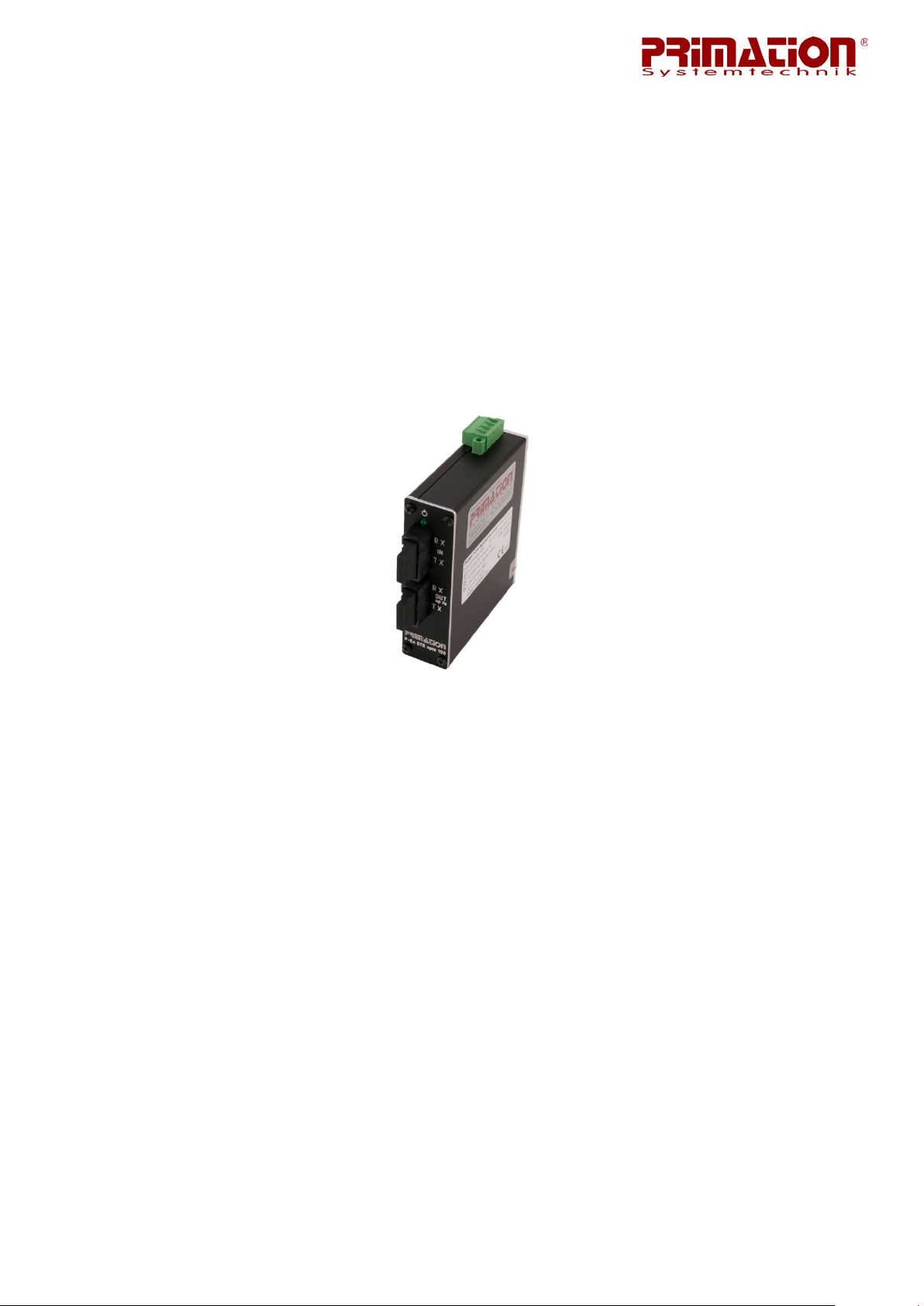
Abb. ähnlich 2
1 Produktbeschreibung
1.1 Allgemeines
Die Optischen Transceiver der P-Ex Reihe wandeln nichteigensichere optische Eingangssignale in eigensichere optische Ausgangssignale um. Die Daten werden hierbei transparent
weitergegeben, somit kann das Gerät auch als optischer Repeater bezeichnet werden. Der
P-Ex OTR opis MC kann bei entsprechender Bestückung auch als Medienkonverter eingesetzt werden. Das Gerät ist mit den Steckertypen „SC“, „ST“ und „LC“ verfügbar.
1.2 Vorteile
• Gehäuse in Aluminium
• Einfache Erzeugung eigensicherer optischer Signale
• Redundante Spannungsversorgung
• -40°C bis +80°C Betriebs- und Lagertemperatur
• Hutschienenmontage und Wandmontage (Option) möglich
1.3 Verpackungsinhalt
Bitte vergewissern Sie sich, dass die Verpackung folgende Teile enthält:
1. P-Ex OTR opis 100, P-Ex OTR opis 1000 oder P-Ex OTR opis MC
2. Bedienungsanleitung
Seite | 1

2 Sicherheitshinweise
2.1 Warnhinweise zu Optischen Transceivern
• Die Installation der der Opt ischen Transceiver darf nur im nicht Ex-Bereich erfol-
gen.
• Spannungsfreiheit während der Installation beachten.
• Das Gerät darf nicht geöffnet werden! Es dürfen keinerlei Änderungen am Gerät
erfolgen.
• Es dürfen keine Bauteile getauscht oder ersetzt werden. Bei nicht spezifizierten
Bauteilen ist der Explosionsschutz nicht mehr gewährleistet.
Dieses Gerät ist werkseitig verschlossen. Nicht öffnen!
• Bei der Version P-Ex OTR opis MC dürfen nur die werksseitig verbauten
Transceiver verwendet werden.
• Optische Schnittstellen mit vorkonfektioniertem LWL-Kabel verbinden.
• Nur „OUT“ Anschluss in Explosionsgefährdete Bereiche führen.
• Gerät vor Schlageinwirkungen schützen und k einen ätzenden/aggressiven Flüs-
sigkeiten, Dämpfen oder Nebeln aussetzen
• Setzen Sie das Gerät unverzüglich außer Betrieb, wenn der Verdacht besteht,
dass das Betriebsmittel nach schädlichen Einwirkungen oder bei allgemeinen
Auffälligkeiten nicht mehr gefahrlos betrieben werden kann (z.B. Eindringen von
Wasser, Fluiden, Einwirkung von Temperaturen außerhalb des spezifizierten Bereiches, etc.)
• Allgemeine gesetzliche Regelungen oder Richtlinien zur Arbeitssicherheit, Unfallverhütungsvorschriften und Umweltschutzgesetze müssen beachtet werden, z.B.
die Betriebssicherheitsverordnung (BetrSichV) bzw. die national geltenden Verordnungen.
• Für elektrische Anlagen sind die einschlägigen Einrichtungs- und Betriebsbestimmungen zu beachten.
• Die Regeln im explosionsgefährdeten Bereich (Richtlinie 99/92/EG) sind zu beachten. Verhindern Sie gefährliche elektrostatische Aufladungen durch das Tragen geeigneter Kleidung und Schuhe. Benutzen Sie keine Gummihandschuhe
o.ä.!
• Vermeiden Sie Wärmeeinwirkungen außerhalb des spezifizierten Temperaturberreichs (siehe Kapitel 3.2 "Allgemeine Daten"). Stellen Sie das Gerät nicht in der
Nähe von Wärmequellen auf, wie beispielsweise Heizkörpern, Luftaustrittsöff-
Seite | 2

nungen einer Klimaanlage, einem Herd und anderen Geräten (einschließlich
Verstärkern), die Wärme abstrahlen.
• Vermeiden Sie Feuchtigkeitseinwirkungen.
• Stecken Sie keine Gegenstände in das Gehäuse oder sonstigen Öffnungen des
P-Ex OTR opis. Öffnungen am Gerät dürfen nicht block iert, zugestellt oder abgedeckt werden.
• Bevor Sie das Gerät in Betrieb nehmen, vergewissern Sie sich, dass es vorschriftsmäßig installiert wurde.
2.2 Installationshinweise
• Der Optische Transceiver ist zum Einbau in ein Gehäuse oder Betriebsmittel des
Schutzgrades IP54 geeignet. Ein solches Gehäuse oder Betriebsmittel ist entweder getrennt bescheinigt oder wurde vom Hersteller nach Auflistung der Gesichtspunkte der Explosionssicherheit für übereinstimmend mit der Norm EN
60079-15 erklärt.
• Allgemeine gesetzliche Regelungen oder Richtlinien zur Arbeitss icherheit, Unfal lverhütungsvorschriften und Umweltschutzgesetze müssen beachtet werden.
Zum Beispiel Betriebssicherheitsverordnung (BetrSichV).
• Umbauten und Veränderungen am Gerät sind nicht zulässig.
Das Gerät ist werkseitig verschlossen. Nicht öffnen!
Das Gerät darf nur im Werk geöffnet werden!
Ein defektes Sicherheitssiegel führt zu Garantieverlust!
2.3 Instandhaltung
Montage/Demontage, Betriebs- und Wartungsarbeiten dürfen nur von ausg ebildetem Fachpersonal durchgeführt werden. Es müssen die gesetzlichen Regelungen und die sonst igen
verbindlichen Richtlinien zur Arbeitssicherheit, zur Unfallverhütung und zum Umweltschutz
eingehalten werden.
Beachten Sie die nationalen Abfallbeseitigungsvorschriften bei der Entsorgung.
2.3.1 Wartung
Bei sachgerechtem Betrieb, unter Beachtung der Montagehinweise und Umgebungsbedingungen, ist keine ständige Wartung erforderlich.
2.3.2 Reparaturhinweise
Wenn Sie ein defektes Gerät zur Reparatur einsenden wollen, setzen Sie sich bitte mit uns in
Verbindung.
E-Mail: service@primation.de
Telefon: +49 (0)89 46 26 0 - 0
Seite | 3

Bitte geben Sie die Seriennummer Ihres zu reparierenden Gerätes an.
2.3.3 Reparaturen
Reparaturen an explosionsgeschützten Betriebsmitteln dürfen nur von dazu befugten Personen mit Or iginal-Ersatzteilen und nach dem Stand der T echnik ausgeführt werden. Die dafür
geltenden Bestimmungen sind zu beachten. Bei Fragen wenden Sie sich bitte an
PRIMATION Systemtechnik GmbH & Co. KG.
2.4 Gesundheits- und Sicherheitsempfehlungen
Alle Komponenten müssen trocken sein, bevor sie an eine externe Stromversorgung angeschlossen werden.
3 Technische Daten
3.1 Explosionsschutz
Typ: P-Ex OTR opis 100
P-Ex OTR opis 1000
P-Ex OTR opis MC
Kennzeichnung:
II (1) D [Ex op is Da] IIIC T135°C bzw. II (2)D [Ex op is Db] IIIC T135°C
I (M1) [Ex op is Ma] I bzw. I (m2) [Ex op is Mb] I
II 3(1)G Ex nA [op is Ga] IIC T4 Gc X bzw. II 3(2)G Ex nA [op is Gb] IIC T4 Gc X
II (1) G [Ex op is Ga] IIC T4 bzw. II (2)G [Ex op is Gb] IIC T4
-40°C ≤ Ta ≤ +80°C
Besondere Bedingungen (erfordert die Kennzeichnung mit dem Symbol „X“): Das Gerät
muss für Anwendungen, welche Kategorie-3-Geräte erfordern, in ein gesondert geprüftes
Gehäuse nach EN-60079-15 eingebaut werden.
Prüfbescheinigung: IBExU 11ATEX1133
weitere Daten siehe EG-Baumusterbescheinigung
3.2 Allgemeine Daten
Abmessungen (LxBxH): 104 x 29 x 114 mm
Betriebstemperatur: -40°C bis +80°C, 10 bis 90% relative Luftfeuchtigkeit,
nicht kondensierend
Lagertemperatur: -40°C bis +80°C, 10 bis 90% relative Luftfeuchtigkeit,
nicht kondensierend
Gehäusematerial: Aluminium
Masse: 325 g
Seite | 4
3.3 Elektrische Daten
Spannungsversorgung: Typ P-Ex***DC Versorgung: DC-Versorgung redundant
Nennspannung: +10V bis +30V DC
Empfohlene Absicherung: 1 AT
Leistungsaufnahme: P
max
≤ 2W
3.4 Ausgangsdaten
Max. Optische Leistung: P
Max. Reichweite: P-Ex OTR opis 100-SC-* Reichweite max. 2.000m
P-Ex OTR opis 100-ST-* Reichweite max. 2.000m
P-Ex OTR opis 1000-LC-* Reichweite max. 550m
P-Ex OTR opis MC 100-*/MM Reichweite max. 2.000m
P-Ex OTR opis MC 100-*/SM Reichweite max 15.000m
P-Ex OTR opis MC 1000-*/MM Reichweite max 550m
P-Ex OTR opis MC 1000-*/SM Reichweite max 10.000m
≤ 35mW
out
3.5 Produktkennzeichnung
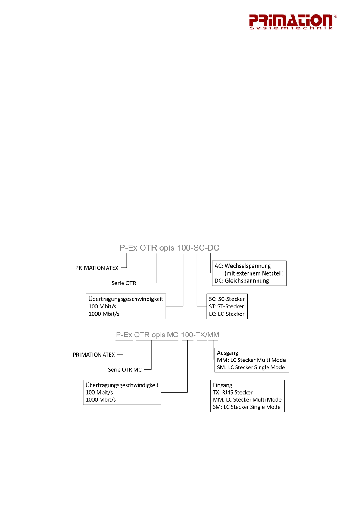
3.5.1 Typenschlüssel
Seite | 5

Abb. ähnlich 3
3.5.2 P-Ex OTR opis 100, P-Ex OTR opis 1000
A
B
C
D
E
A Klemme Spannungsversorgung
B Power LED
C SC, ST, LC Input
D SC, ST, LC opis Output
E Typenschild
P-Ex OTR opis 100 P-Ex OTR opis 1000
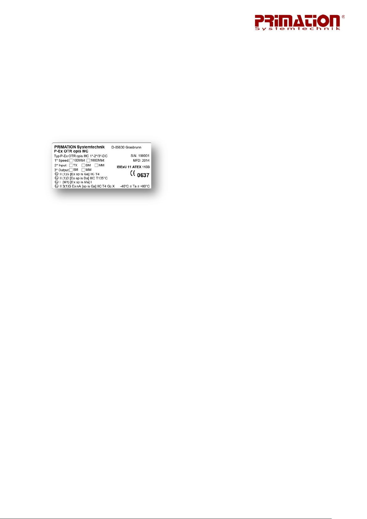
3.5.3 P-Ex OTR opis MC
A
B
C
D
E
Seite | 6
A Klemme Spannungsversorgung
B Power LED, Link Status LEDs (Kapitel 7.2)
C LC MM, LC SM oder TX Eingang
D LC MM oder LC SM Ausgang
E T ypenschild (siehe unten)
P-Ex OTR opis MC
Die Geschwindigkeit und die verbauten Transceiver Typen sind durch Kr euze auf dem Typenschild markiert.
3.6 Angewandte Richtlinien und Normen
Richtlinie:
RoHs 2002/95/EC
Normen für Explosionsschutz:
Elektr. Betriebsmittel für gasexplosionsgefährdete Bereiche:
Teil 0: Allgemeine Anforderungen EN 60 079-0: 2012
Elektr. Betriebsmittel für gasexplosionsgefährdete Bereiche:
Teil 28: Schutz von Einrichtungen und Übertragungssystemen,
die mit optischer Strahlung arbeiten EN 60 079-28: 2007
EN 60 079-15:2010
4 Montage
4.1 Hutschienenmontage
Die P-Ex OTR opis Serie ist standardmäßig f ür die Montage auf einem Hutschienensystem
ausgelegt. Achten Sie bei der Montage darauf, dass der Transceiver richtig auf der Hutschiene einrastet und ein fester Sitz sichergestellt ist.
Zur Demontage ziehen Sie die Lasche am unteren Ende der Hutschienenklammer in Richtung des Gerätes und kippen Sie den P-Ex OTR opis nach oben aus der Hutschiene heraus.
Bitte beachten Sie, dass vor der Demontage alle elektrischen und optischen Verbindungen
getrennt wurden.
Seite | 7

4.2 Wandmontage
Bei der Option für die Wandmontage ist die Rückenplatte des Gerätes mit den entsprechenden Bohrungen zur Befestigung versehen. Es ist darauf zu achten, dass je nach Art der
Wand entsprechendes Befestigungsmaterial verwendet werden muss.
Vor der Demontage müssen alle elektrischen und optischen Verbindungen getrennt werden.
5 Anschlussbelegung
5.1 P-Ex OTR opis 100, P-Ex OTR opis 1000, P-Ex OTR opis MC
5.1.1 Spannungsversorgung
Klemmenbelegung (X1 Power) der P-Ex OTR opis * Modellreihe
Klemme: Bezeichnung:
V1 + 10-24V DC
V1 - GND
V2 + 10-24V DC
V2 - GND
• 0,2 - 2,5mm
• 0,2 - 2,5mm
2
/ 24AWG-16AWG Leiterquerschnitt flexibel
2 /
24AWG-16AWG Leiterquerschnitt starr
• max. 1 Leitung je Klemme
• Anzugsdrehmoment max. 0,6Nm
5.1.2 Datenleitungen
P-Ex OTR opis 100-ST
• LWL Stecker Typ: ST
• 100 Base FX
• Empfohlene Faser: Multimode 50/125µm
P-Ex OTR opis 100-SC
• LWL Stecker Typ: SC
• 100 Base FX
• Empfohlene Faser: Multimode 50/125µm
Seite | 8

P-Ex OTR opis 1000-LC
• LWL Stecker Typ: LC
• 1000 Base FX
• Empfohlene Faser: Multimode 50/125µm
P-Ex OTR opis MC
• LWL Stecker Typ: LC
• 100 Base FX
o Empfohlene Faser:
Multimode 50/125µm
Singlemode 10/125µm
• 1000 Base FX
o Empfohlene Faser:
Multimode 50/125µm
Singlemode 9/125µm
• Kupfer Steckertyp: RJ45
6 Inbetriebnahme
6.1 P-Ex OTR opis 100, P-Ex OTR opis 1000, P-Ex OTR opis MC
Um eine einwandfreie Funktion und eine lange Lebensdauer der Geräte zu erhalten, ist es
notwendig auf eine sorgfältige Behandlung der Geräte zu achten. Im Kapitel 4 "Montage"
wird beschrieben wie Sie die Optischen Transceiver montieren müssen, um z.B. Beschädigungen durch herunterfallende Teile zu vermeiden.
Benutzen Sie die Geräte nur in technisch einwandfreiem Zustand.
Bevor Sie den P-Ex OTR opis 100, P-Ex OTR opis 1000 oder P-Ex OTR opis MC zum ersten
Mal verwenden, müssen Sie diesen einwandfrei mont iert und installiert haben (gemäß Kapitel 5 "Anschlussbelegung").
Seite | 9

7 Funktionsweise P-Ex OTR
7.1 Vorderseite
P-Ex OTR opis 100 P-Ex OTR opis 1000 P-Ex OTR opis MC
7.2 Status-LED
POWER: Grüne LED leuchtet wenn die Spannungsversorgung hergestellt ist
RX loss*: Orange LED leuchtet wenn die Datenverbindung unterbrochen ist
TX fault*: Rote LED leuchtet wenn im Transceiver ein Fehler auftritt
*nur bei P-Ex OTR opi s MC
7.3 Datenleitungen
Für den Anschluss der Datenleitungen an die LWL-Ports sind nur vorkonfektionierte Kabel zu
verwenden. Es ist sicherzustellen, dass das Gerät ausgeschalten ist während die Leitung en
angeschlossen werden. Bitte beachten Sie die unter Punkt „5.1. 2 Datenleitungen“ angegebenen Spezifikationen für die Lichtwellenleiter.
Achtung: Das Herstellen einer Port zu Port Verbindung an den Geräten ist nicht zulässig
und kann dazu führen, dass die Geräte beschädigt werden.
7.4 Fehlerbehebung
• vergewissern Sie sich, dass die POWER LED eingeschaltet ist
• stellen Sie sicher, dass Sie je nach gewähltem Modell die richtige Spannungsversor-
gung hergestellt haben.
Achtung: Der Einschaltstrom kann den Betriebsstrom um das doppelte übersteigen!
• überprüfen Sie die Verkabelung zwischen den beiden Ports, bei P-Ex OTR opis MC
wird ein Verbindungsfehler durch die orange RX loss LED signalisiert.
Seite | 10

7.5 Support
E-Mail: technik@primation.de
Telefon: +49 (0)89 46 26 0 - 0
8 Zusatzinformationen
8.1 Links
http://www.primation.de Webseite PRIMATION Systemtechnik
http://www.primation.de/de_atex.html ATEX Produktwebseite
8.2 Informationen rund um den Explosionsschutz
Hersteller explosionsgeschützter Systeme, Geräte und Komponenten, Errichter und Betreiber von Anlagen schaffen gemeinsam die Voraussetzungen für den sicheren Betrieb von
Anlagen in explosionsgefährdeten Bereichen. Beim Betreiber ist das W issen der Mitarbeiter
um die Zusammenhänge des Explosionsschutzes und um die getroffenen Maßnahme, die zu
ihrer Vermeidung angewendet werden, eine wichtige Voraussetzung dafür.
Über den Inhalt des Explosionsschutzdokumentes nach Richtlinie 1999/92/EG (in der Bundesrepublik umgesetzt in der Betriebssicherheitsverordnung BetrSichV) und die betrieblich
geltenden Regelungen, sollten die Mitarbeiter regelmäßig g eschult und mit schriftlichen Betriebsanweisung informiert werden. Eine Kontrolle dieser Maßnahmen muss ebenfalls regelmäßig erfolgen.
Baubestimmungen für explosionsgeschützte Systeme, Geräte und Komponenten Betriebsmittel
Gefahren, die beim Umgang mit brennbaren Gasen, Dämpfen und Stäuben auftreten, beruhen auf einheitlichen chemischen und physikalischen Abläufen. Deshalb kann auch die Abwehr dieser Gefahren nur einheitlich erfolgen.
In der Internationalen Elektrotechnischen Kommission IEC, in den Europäischen Normengremien CENELEC und CEN sowie in DKE und DIN sind inzwischen nahezu durchgängig einheitliche Forderungen formuliert.
Die Einhaltung wird von den Herstellern und Betreibern gefordert und bei erhöhten Schutzanforderungen von anerkannten Prüfstellen und Behörden überwacht.
9 Versand- und Verpackungshinweis
Wichtiger Hinweis zum Transport und Versand
Empfindliche Geräte !
Es ist unbedingt erforderlich das Gerät in der Originalverpackung zu versenden, um
Beschädigungen am Gerät zu vermeiden.
Seite | 11


10 Maßzeichnung P-Ex OTR opis MC
10.1 P-Ex OTR opis MC mit zwei Glasfaser Modulen
Seite | 11

10.2 P-Ex OTR opis MC mit einem Kupfer und einem Glasfaser Modul
Seite | 12

11 Prüfbescheinigungen
11.1 EG-Konformitätserklärung
Seite | 13

11.2 EG-Baumusterprüfbescheinigung IBExU11ATEX1133
Seite | 14

Seite | 15

11.3 Ergänzung zur EG-Baumusterprüfbeschinigung IBExU11ATEX1133
Seite | 16

User Manual
Fig. similar
Optical Transceiver
Type
Type
P-Ex OTR opis 100
P-Ex OTR opis 1000
Type P-Ex OTR opis MC*
*all information are also valid for
P-Ex OTR opis 100-SM15
P-Ex OTR opis 1000-SM10
Version: 3.10
Document No. EX-11-200002
Last updated: 19
Subject to technical changes
th
December 2014
Contents
German 1 - 16
English 17 - 29
PRIMATION Systemtechnik Tel.: +49 (0)89 46 26 0 - 0
GmbH & Co. KG Fax: +49 (0)89 46 26 0 - 210
Bretonischer Ring 13 E-mail: info@primation.de
85630 Grasbrunn Web: http://www.primation.de
Germany
Page


Before commissioning
Please read the operating instructions carefully and in full!
Target group:
experienced specialists in compliance with the Directives 99/92/EC, IEC 60079-19 and EN
60079-17.
Please note:
This user manual contains important information, safety instructions and test certifications,
which are necessary for err or-free functioning during the operation and handling of the optical transceiver. If these notes and safety instructions are not followed, proper use cannot be
guaranteed.
Changes to the devices which have not been expressly approved by PRIMATION Systemtechnik GmbH & Co. KG (PRIMATION), will result in the forfeit of the operating perm it for
the device in question. Non-compliance will result in the forfeit of claims under warranty. T he
warranty will be forfeited if damage occurs to the product as the result of inappropriate handling, excessive loading, inadequate maintenance, abnormal operating conditions or
transport damage. Natural wear and tear is also excluded from the warranty.
PRIMATION reserves the right to make changes to the content of this document without prior
notice. The accuracy of the information is therefore not guaranteed. In case of doubt, the
German safety instructions take precedence, as translation and printing errors cannot be
ruled out. In the case of a legal dispute, the "General Terms and Conditions" of PRIMATION
shall also apply.
The current versions of the data sheets, manuals, certificates and the EC Declaration of Conformity can be downloaded from the "ATEX" product page at www.primation.de or requested
directly from PRIMATION.
Documentation
The documents are available in German and English.
Visit our website http://www.primation.de for information about your specific product.


Pictograms and Safety Information
Indicates risk of injury or death if particular rules are not followed. Please observe all
safety precautions indicated with this pictogram.
Indicates a potentially dangerous situation which could lead to material damage if
the situation is not avoided.
Indicates useful tips, recommendations and information for efficient, environmentally
friendly and error-free operation.

Contents
1 Product Description .......................................................................................................16
1.1 General ..................................................................................................................16
1.2 Advantages ............................................................................................................16
1.3 Package Contents ..................................................................................................16
2 Safety Information .........................................................................................................17
2.1 Warnings about optical transceivers .......................................................................17
2.2 Installation Instructions ...........................................................................................18
2.3 Maintenance ..........................................................................................................18
2.3.1 Maintenance ...................................................................................................18
2.3.2 Repair Information ...........................................................................................18
2.3.3 Repairs ...........................................................................................................18
2.4 Health and Safety Recommendations ....................................................................19
3 Technical Data ..............................................................................................................19
3.1 Blast proofing .........................................................................................................19
3.2 Model: P-Ex OTR opis 100 P-Ex OTR opis 1000 P-Ex OTR opis MC ...19
3.3 General Data ..........................................................................................................19
3.4 Electrical Data ........................................................................................................19
3.5 Output Data ............................................................................................................20
3.6 Product Designation ...............................................................................................20
3.6.1 Type Code ......................................................................................................20
3.6.2 P-Ex OTR opis 100, P-Ex OTR opis 1000 .......................................................21
3.6.3 P-Ex OTR opis MC ..........................................................................................21
3.7 Applicable Directives and Standards ......................................................................22
4 Assembly ......................................................................................................................22
4.1 Top-hat rail assembly .............................................................................................22
4.2 Wall assembly ........................................................................................................23
5 Terminal Assignment .....................................................................................................23
5.1 P-Ex OTR opis 100, P-Ex OTR opis 1000, P-Ex OTR opis MC ..............................23
5.1.1 Power Supply ..................................................................................................23
5.1.2 Data Lines .......................................................................................................23
6 Commissioning ..............................................................................................................24
6.1 P-Ex OTR opis 100, P-Ex OTR opis 1000, P-Ex OTR opis MC ..............................24
7 P-Ex OTR opis functions ...............................................................................................25
7.1 Front Side ..............................................................................................................25
7.2 Status LED .............................................................................................................25

7.3 Data Lines ..............................................................................................................25
7.4 Troubleshooting .....................................................................................................25
7.5 Support ..................................................................................................................25
8 Additional Information ....................................................................................................26
8.1 Links ......................................................................................................................26
8.2 Information about Blast Proofing ............................................................................26
9 Shipping and Packaging Information .............................................................................26
10 Drawings P-Ex OT R opis MC .....................................................................................24
10.1 P-Ex OTR opis MC with two fiber optic modules ....................................................24
10.2 P-Ex OTR opis MC with one fiber optic and one copper module ............................25
11 Test Certificates .........................................................................................................26
11.1 EC Declar a tion of Conformity .................................................................................26
11.2 EC Type Examination Certificate IBExU11ATEX11133 ..........................................27
11.3 Addition to EC Type Examination Certificate IBExU11ATEX1133 ..........................29

1 Product Description
1.1 General
The optical transceivers in the P-Ex range convert non-intrinsically safe opt ical input signals
into intrinsically safe optical output signals. The data is passed on transparently so that the
device can also be designated as an optical repeater. The P-Ex-OTR opis MC can be used
as a media converter if loaded with the right SFPs. The device is available with connector
types "SC“, "ST“ and "LC“.
Fig. similar
1.2 Advantages
• Aluminum housing
• Simple generation of intrinsically safe optical signals
• Redundant voltage supply
• Operating and storage temperature of -40°C to +80°C
• Top-hat rail and wall assembly (option) possible
1.3 Package Contents
Please ensure that the package contains the following parts:
1. P-Ex OTR opis 100, P-Ex OTR opis 1000 or P-Ex OTR opis MC
2. User manual
Page | 16

2 Safety Information
2.1 Warnings about optical transceivers
• The optical transceiver must only be installed in non-explosive areas.
• Ensure that the power is switched off during installation.
• The device must not be opened! Changes must not be made to the device.
• Components must not be exchanged or replaced. If components other than those
specified are used, blast proofing is no longer guaranteed.
This device is sealed at the factory. Do not open the device!
• The P-Ex OTR opis MC must be used with the transceivers built in ex works
• Connect the optical interfaces using prefabricated optical fiber cables
• Only "OUT“ cables may be led into areas at risk of explosion.
• Protect the device from knocks and do not expose it to any corrosive/aggressive
fluids, steams or mists.
• The device must immediately be put out of operation if it is suspected that the
operating equipment can no longer be operated safely after harmful influences or
in the event of general problems (e.g. penetration of water or fluids, effect of
temperatures outside the specified range, etc.)
• General legal regulations or guidelines regarding safety at work , acc ident prevention regulations and environmental protection laws must be followed, e.g. Betriebssicherheitsverordnung (BetrSichV, industrial safety act) or applicable national laws.
• For electrical systems, the relevant installation and operating regulations must be
followed.
• The rules for potentially explosive areas (Directive 99/92/EC) must be followed.
Prevent hazardous electrostatic charging by wearing suitable clothing and shoes.
Do not use rubber gloves or such like!
• Avoid exposure to heat outside of the specified temperature range (see section
3.2 "General Data"). Do not place the device close to sources of heat such as
heaters, air outlets of air conditioning systems, cookers or other devices (including amplifiers) which emit heat.
• Avoid exposure to moisture.
Page | 17

• Do not insert any objects into the housing or other openings of the P-Ex OTR
opis. Openings on the device must not be blocked, closed or covered.
• Before commissioning the device, ensure that it has been installed in accordance
with the regulations.
2.2 Installation Instructions
• The optical transceiver is suitable for installation in a housing or operating facilities at protection level IP54. Such a housing or operating facility is either cer tified
separately or was declared compliant with the EN 60079-15 standard by the
manufacturer, having listed the main principles of blast protection.
• Ensure compliance with general legal regulations or guidelines relating to safety
at work, accident prevention regulations and environmental protection laws. Example: Industrial Safety Act (BetrSichV).
• Do not convert or modify the device.
The device is sealed at the factory. Do not open the device!
The device may only be opened in the factory!
The warranty will lapse if the security seal is broken!
2.3 Maintenance
Assembly/dismantling and operating and maintenance work may only be performed by
trained specialist personnel. Legal regulations and other binding guidelines regarding safety
at work, accident prevention and environmental protection must be followed.
When disposing of the device, follow the national waste disposal regulations.
2.3.1 Maintenance
If correctly operated in compliance with the assembly instructions and cor rect environmental
conditions, no regular maintenance is required.
2.3.2 Repair Information
If you would like to send us a defective device for repair, please contact us.
E-mail: service@primation.de
Telephone: +49 (0)89 46 26 0 - 0
Please specify the serial number of the device to be repaired.
2.3.3 Repairs
Repairs to blast-proofed operating equipment may only be performed by persons authorized
to do so using original spare parts and the most recent technology. The applicable regulations must be followed. If you have any queries, please contact
PRIMATION Systemtechnik GmbH & Co. KG.
Page | 18

2.4 Health and Safety Recommendations
All components must be dry before being connected to an external power supply.
3 Technical Data
3.1 Blast proofing
3.2 Model: P-Ex OTR opis 100
P-Ex OTR opis 1000
P-Ex OTR opis MC
Labeling: II (1) G [Ex op is Ga] IIC T4 bzw. II (2)G [Ex op is Gb] IIC T4
II (1) D [Ex op is Da] IIIC T135°C bzw. II (2)D [Ex op is Db] IIIC T135°C
I (M1) [Ex op is Ma] I bzw. I (m2) [Ex op is Mb] I
II 3(1)G Ex nA [op is Ga] IIC T4 Gc X bzw. II 3(2)G Ex nA [op is Gb] IIC T4 Gc X
-40°C ≤ Ta ≤ +80°C
Special conditions (A marking with “X” is required): If used in areas ehere equipment of
Category 3 is required, the optical transceiver must be installed in an enclosure which has
been tested separately.
Test certification: IBExU 11ATEX1133
For further data, see EC Type Examination Certificate
3.3 General Data
Dimensions (LxWxH): 104 x 29 x 114 mm
Operating temperature: -40°C to +80°C, 10 to 90% relative humidity,
non-condensing
Storage temperature: -40°C to +80°C, 10 to 90% relative humidity,
non-condensing
Housing material: Aluminum
Mass: 325 g
3.4 Electrical Data
Power supply: Model P-Ex***DC Power supply: DC supply redundant
Nominal voltage: +10V to +30V DC
Recom. fuse: 1 Ampere (slow-blow)
Power consumption: P
Page | 19
max
≤ 2W

3.5 Output Data
Max. optical power: P
≤ 35mW
out
Max. operating range:
P-Ex OTR opis 100-SC-* Max. operating range 2.000m
P-Ex OTR opis 100-ST-* Max. operat ing range 2.000m
P-Ex OTR opis 1000-LC-* Max. operating range 550m
P-Ex OTR opis MC 100-*/MM Max. operating range 2.000m
P-Ex OTR opis MC 100-*/SM Max. operating range 15.000m
P-Ex OTR opis MC 1000-*/MM Max. operating range 550m
P-Ex OTR opis MC 1000-*/SM Max. operating range 10.000m
3.6 Product Designation
3.6.1 Type Code
Page | 20

Fig. similar
3.6.2 P-Ex OTR opis 100, P-Ex OTR opis 1000
A
B
C
D
E
A Terminal Voltage supply
B Power LED
C SC, ST, LC Input
D SC, ST, LC opis Output
E Type plate
P-Ex OTR opis 100 P-Ex OTR opis 1000
3.6.3 P-Ex OTR opis MC
A
B
C
D
E
Page | 21

A Terminal Voltage supply
B Power LED, Link Status LEDs (Chapter 7.2)
C LC MM, LC SM or TX Input
D LC MM or LCSM opis Output
E Type plate
P-Ex OTR opis MC
The speed and the built in transceiver types are marked on the Type plate.
3.7 Applicable Directives and Standards
Directive:
RoHs 2002/95/EC
Standards for explosion protection:
Electr. operating equipment for areas at risk of gas explosion:
Part 0: General requirements EN 60 079-0: 2012
Electr. operating equipment for areas at risk of gas explosion:
Part 28: Protection of equipment and transfer systems
which work with optical radiation EN 60 079-28: 2007
EN 60 079-15: 2010
4 Assembly
4.1 Top-hat rail assembly
The P-Ex OTR opis series is designed as standard for assembly on a top-hat rail system.
When assembling, ensure that the transceiver engages correctly on the top-hat rail and is
seated securely.
To disassembly, pull the strap at the bottom of the top-hat rail clip towards the device and tilt
the P-Ex OTR opis upwards and off the top-hat rail. Ensure that all electrical and optical connections have been disconnected before disassembly.
Page | 22

4.2 Wall assembly
If the wall assembly option is selected, the backplate of the device is supplied with corresponding drill holes for attachment. Ensure that you use the appropriate fixing material for
the type of wall you have.
Ensure that all electrical and optical connections are disconnected before disassembly.
5 Terminal Assignment
5.1 P-Ex OTR opis 100, P-Ex OTR opis 1000, P-Ex OTR opis MC
5.1.1 Power Supply
Terminal assignment (X1 Power) for P-Ex OTR opis * Model series
Terminal: Designation:
V1 + 10-24V DC
V1 - GND
V2 + 10-24V DC
V2 - GND
• 0.2 - 2.5mm
• 0.2 - 2.5mm
2
/ 24AWG-16AWG conductor cross section, flexible
2
/ 24AWG-16AWG conductor cross section, rigid
• Max. 1 line per terminal
• Tightening torque max. 0.6Nm
5.1.2 Data Lines
P-Ex OTR opis 100-ST
• Fiber-optic connector type: ST
• 100 Base FX
• Recommended fiber: Multimode 50/125µm
P-Ex OTR opis 100-SC
• Fiber-optic connector type: SC
• 100 Base FX
• Recommended fiber: Multimode 50/125µm
Page | 23

P-Ex OTR opis 1000-LC
• Fiber-optic connector type: LC
• 1000 Base FX
• Recommended fiber: Multimode 50/125µm
P-Ex OTR opis MC
• Fiber-optic connector type: LC
• 100 Base FX
o Recommended fiber
Multimode 50/125µm
Singlemode 9/125µm
• 1000 Base FX
o Recommended fiber
Multimode 50/125µm
Singlemode 9/125µm
• Copper connector type: RJ45
6 Commissioning
6.1 P-Ex OTR opis 100, P-Ex OTR opis 1000, P-Ex OTR opis MC
In order to achieve perfect functioning and a long ser vice life for the devices, it is necessary
to ensure careful handling of the devices. Section 4 "Assembly" describes how the optical
transceivers must be assembled in order to avoid damage from falling parts.
The devices must only be used in perfect technical condition.
Before using the P-Ex OTR opis 100 or P-Ex OTR opis 1000 for the first time, they must
have been correctly assembled and installed (in accordance with section 5 "Terminal Assignment").
Page | 24

7 P-Ex OTR opis functions
7.1 Front Side
P-Ex OTR opis 100 P-Ex O TR opis 1000 P-Ex OTR opis MC
7.2 Status LED
POWER: Green LED lights up when the power supply is established
RX loss*: Orange LED lights up when data connection is disconnected
TX fault*: Red LED lights up if an error inside the transceiver occurs
*only available at P-Ex OTR op i s MC
7.3 Data Lines
You must only use pre-fabricated cables to connect data lines to the fiber-optic cable port s.
Ensure that the device is switched off while the cables ar e being connected. Please observe
the specifications for the fiber-optic cables indicated in section 5.1.2 "Data Lines“.
Note: Do not create a port-to-port connection on the devices, as this may damage the devices.
7.4 Troubleshooting
• Ensure that the POWER LED is on
• Ensure that the correct power supply has been established for the chosen model.
Note: The start-up current may be twice as great as the operating current!
• Check the wiring between both ports at the P-Ex OTR opis 1000-SM10 a link failure
is indicated by the orange RX loss LED.
7.5 Support
E-mail: technik@primation.de
Telephone: +49 (0)89 46 26 0 - 0
Page | 25

8 Additional Information
8.1 Links
http://www.primation.de PRIMATION Systemtechnik website
http://www.primation.de/de_atex.html ATEX product website
8.2 Information about Blast Proofing
Manufacturers of explosion-protected systems, devices and components and installers and
operators of systems are together responsible for fulfilling the prerequisites for safe operation
of systems in potentially explosive areas. It is important that the operator should ensure that
their employees know how the danger of explosions is likely to ar ise and the measures that
are taken to avert it.
Employees should receive regular training and written instructions regarding the content of
the blast proofing document in accordance with Directive 1999/92/EC (implemented in the
Federal Republic of Germany as the Betriebssicherheitsverordnung BetrSichV) and the applicable operational regulations. Regular checks of these measures must also be carried out.
Building regulations for blast-proofed systems, devices and components - operating
equipment
Hazards which occur during the handling of flammable gases, steams and dusts are based
on uniform chemical and physical processes. Therefore, the prevention of these hazards
must also always be uniform.
Almost entirely uniform requirements have now been formulated by the International Electrotechnical Commission (IEC), the European standardization committees CENELEC and CEN
as well as DKE and DIN.
Compliance by manufacturers and operators is required and, in cases of increased protection requirements, monitored by approved testing organizations and authorities.
9 Shipping and Packaging I nf orm a t ion
Important information about transport and shipping
Sensitive equipment!
It is absolutely essential to ship the device in its original packaging in order to avoid
damage to the device.
Page | 26


10 Drawings P-Ex OTR opis MC
10.1 P-Ex OTR opis MC with two fiber optic modules
Page | 24

10.2 P-Ex OTR opis MC with one fiber optic and one copper module
Page | 25

11 Test Certificates
11.1 EC Declaration of Conformity
Page | 26

11.2 EC Type Examination Certificate IBExU11ATEX11133
Page | 27

Page | 28

11.3 Addition to EC Type Examination Certificate IBExU11ATEX1133
Page | 29
 Loading...