


Ethernet-Switches und Medienkonverter
Typ P-Ex 1002MC
Typ P-Ex 1003GX2
Typ P-Ex 1005TX
ATEX Version
Zone 1 / 21 / M2
Version: 1.02
Dokumenten-Nr. EX-11-200001
Stand: 15.05.2012
Technische Änderungen vorbehalten!
Inhalt Seite
Deutsch 1 - 17
Englisch 18 - 35
PRIMATION Systemtechnik Tel.: +49 (0)89 46 26 0 - 0
GmbH & Co. KG Fax: +49 (0)89 46 26 0 - 210
Bretonischer Ring 13 Mail: info@primation.de
85630 Grasbrunn Web: http://www.primation.de
Deutschland
Bedienungsanleitung


Vor Inbetriebnahme
Bitte lesen Sie die Bedienungsanleitung vollständig und sorgfältig durch!
Zielgruppe:
Erfahrene Fachkräfte unter Einhaltung der Richtlinien 99/92/EG, IEC 60079-19 sowie EN
60079-17.
Bitte beachten:
Dieses Benutzerhandbuch beinhaltet wichtige Hinweise, Sicherheitsvorschriften und Prüfbescheinigungen, die für eine einwandfreie Funktionsweise bei der Bedienung und Handhabung der Ethernet-Switches und Medienkonverter erforderlich sind. Werden die Hinweise
und Sicherheitsvorschriften nicht beachtet, ist die bestimmungsgemäße Verwendung in explosionsgefährdeten Bereichen nicht gewährleistet.
Änderungen an den Geräten, die nicht ausdrücklich durch PRIMATION Systemtechnik
GmbH & Co. KG (PRIMATION) genehmigt wurden, führen zum Erlöschen der Betriebserlaubnis für das betreffende Gerät. Eine Nichteinhaltung schließt Gewährleistungsansprüche
aus. Die Gewährleistung erlischt, wenn Schäden an dem Produkt eintreten, die auf unsachgemäße Behandlung, übermäßige Beanspruchung, ungenügende Instandhaltung, anormale
Betriebsbedingungen sowie auf Transportschäden zurückzuführen sind. Natürlicher Verschleiß ist ebenfalls von der Gewährleistung ausgeschlossen.
PRIMATION behält sich vor, inhaltliche Änderungen an diesem Dokument ohne Ankündigung vorzunehmen. Die Richtigkeit der Informationen ist ohne Gewähr. Im Zweifelsfall sind
die deutschen Sicherheitshinweise gültig, da Übersetzungs- und Druckfehlern nicht ausgeschlossen werden können. Im Rechtsfall gelten ergänzend die "Allgemeinen Geschäftsbedingungen" der PRIMATION.
Die jeweils aktuelle Version der Datenblätter, Handbücher, Zertifikate und der EGKonformitätserklärung können auf der Produktseite "ATEX" unter www.primation.de heruntergeladen oder direkt bei der PRIMATION angefordert werden.
Dokumentation
Die Unterlagen sind in deutsch und englisch verfügbar.
Besuchen Sie unsere Webseite http://www.primation.de und informieren Sie sich über Ihr
spezielles Produkt.


Piktogramme und Sicherheitshinweise
Signalisiert Verletzungs- oder Lebensgefahr, sofern bestimmte Verhaltensregeln
missachtet werden. Befolgen Sie bitte alle Sicherheitsvorkehrungen, die mit diesem
Piktogramm gekennzeichnet sind.
Kennzeichnet eine möglicherweise gefährliche Situation, die zu Sachschäden führen kann, wenn sie nicht gemieden wird.
Kennzeichnet nützliche Tipps, Empfehlungen und Informationen für einen effizienten, umweltgerechten und störungsfreien Betrieb.

Inhalt
1. Produktbeschreibung ..................................................................................................... 1
1.1 Allgemeines ............................................................................................................ 1
1.2 Vorteile .................................................................................................................... 1
1.3 Verpackungsinhalt ................................................................................................... 2
2 Sicherheitshinweise ........................................................................................................ 2
2.1 Warnhinweise zu Ethernet-Switches und Medienkonvertern ................................... 2
2.2 Warnhinweise zu Lasergeräten ............................................................................... 3
2.3 Installationshinweise ............................................................................................... 3
2.3.1 Installationsrichtlinien ....................................................................................... 3
2.4 Instandhaltung ......................................................................................................... 4
2.4.1 Wartung ........................................................................................................... 4
2.4.2 Reparaturhinweise ........................................................................................... 4
2.4.3 Inspektion ......................................................................................................... 4
2.4.4 Reparaturen ..................................................................................................... 4
2.5 Gesundheits- und Sicherheitsempfehlungen ........................................................... 5
3 Technische Daten .......................................................................................................... 5
3.1 Explosionsschutz .................................................................................................... 5
3.2 Allgemeine Daten .................................................................................................... 5
3.3 Elektrische Daten .................................................................................................... 5
3.4 Ausgangsdaten ....................................................................................................... 6
3.5 Produktkennzeichnung ............................................................................................ 6
3.5.1 Typenschlüssel ................................................................................................ 6
3.5.2 P-Ex1005TX ..................................................................................................... 6
3.5.3 P-Ex1002MC und 1003GX2 ............................................................................. 7
3.6 Angewandte Richtlinien und Normen ...................................................................... 8
4 Montage ......................................................................................................................... 9
4.1 Bohrplan .................................................................................................................. 9
5 Anschlussbelegung .......................................................................................................10
5.1 Anschlussbelegung für P-Ex1002MC, P-Ex1003GX2, P-Ex1005TX .......................10
5.1.1 Spannungsversorgung ....................................................................................10
5.1.2 Datenleitungen ................................................................................................11
6 Inbetriebnahme .............................................................................................................12
6.1 P-Ex1002MC, P-Ex1003GX2, P-Ex1005TX ...........................................................12
7 Funktionsweise P-Ex1002MC, P-Ex1003GX2, P-Ex1005TX .........................................12
7.1 Vorderseite .............................................................................................................12

7.2 Status-LEDs ...........................................................................................................13
7.3 Datenleitungen .......................................................................................................13
7.4 Fehlerbehebung .....................................................................................................14
7.5 Support ..................................................................................................................14
8 Zusatzinformationen ......................................................................................................14
8.1 Links ......................................................................................................................14
8.2 Informationen rund um den Explosionsschutz ........................................................14
9 Versand und Verpackungshinweis ................................................................................15
10 Prüfbescheinigungen .................................................................................................15
10.1 EG-Konformitätserklärung ......................................................................................15
10.2 EG-Baumusterprüfbescheinigung IBExU 11 ATEX 1058 ........................................16


Seite | 1
1. Produktbeschreibung
1.1 Allgemeines
Die Ethernet-Switches und Medienkonverter P-Ex1002MC, P-Ex1003GX2 und P-Ex1005TX
werden in explosionsgefährdeten Bereichen der Gerätegruppe I und II als stationäre Geräte
verwendet. Sie dienen zur Übertragung von optischen oder elektrischen Datensignalen bis
zu einer Bandbreite von 1 Gbit/s.
Die Produkte gibt es in zwei verschiedenen Ausführungen, mit Aluminiumgehäuse für den
Einsatz in Zone 1 und Zone 21 sowie in einem Edelstahlgehäuse für den Einsatz im Bereich
Mining M2.
1.2 Vorteile
• Gehäuse in Aluminium oder Edelstahl
• Direkte Montage in ATEX Zone 1 und 21 sowie M2
• Kein zusätzliches Netzteil erforderlich
• Anschluss weiterer Geräte mit einfachen Mitteln möglich
• 5 Port Gigabit-Switch und 3 Port TX/FX-Switch in identischer Gehäuseform erhältlich
• IEEE 802.3
• Jumbo Frame Unterstützung
• -40°C bis +80°C Betriebs- und Lagertemperatur
• Unterstützt Full/Half Duplex
• Datendurchsatz von bis zu 10Gb/s
• Store-and-foreward Technologie
• LED Link/Activity Status Indikatoren

Seite | 2
1.3 Verpackungsinhalt
Bitte vergewissern Sie sich, dass die Verpackung folgende Teile enthält:
1. P-Ex1002MC, P-Ex1003GX2 oder P-Ex1005TX
2. Bedienungsanleitung
2 Sicherheitshinweise
2.1 Warnhinweise zu Ethernet-Switches und Medienkonvertern
• Die Installation der Switches und Medienkonverter erfolgt nur in zugelassenen
Ex-Bereichen der Gerätekategorie I und II und in den Zonen M2, 1 und 21.
• Spannungsfreiheit während der Installation beachten.
• Das Gerät darf auch außerhalb des explosionsgefährdeten Bereiches nicht ge-
öffnet werden! Es dürfen keinerlei Änderungen am Gerät erfolgen.
• Es dürfen keine Bauteile getauscht oder ersetzt werden. Bei nicht spezifizierten
Bauteilen ist der Explosionsschutz nicht mehr gewährleistet.
Dieses Gerät ist werkseitig verschlossen. Nicht öffnen!
• Klemmanschlussraum nicht unter Spannung öffnen!
• Das PA-Anschlussteil (Potentialausgleich-Anschlussteil) ist mit dem Potential-
ausgleichsleiter des explosionsgefährdeten Bereiches zu verbinden. Da die eigensicheren Stromkreise galvanisch mit Erde verbunden sind, muss im gesamten Verlauf der Errichtung der eigensicheren Stromkreise Potentialausgleich bestehen.
• Gerät vor Schlageinwirkungen schützen und keinen ätzenden/aggressiven Flüssigkeiten, Dämpfen oder Nebeln aussetzen! Bei Funktionsstörungen oder Gehäuseschäden ist das Gerät unverzüglich aus dem explosionsgefährdeten Bereich zu bringen.
• Setzen Sie das Gerät unverzüglich außer Betrieb, wenn der Verdacht besteht,
dass das Betriebsmittel nach schädlichen Einwirkungen oder bei allgemeinen
Auffälligkeiten nicht mehr gefahrlos betrieben werden kann (z.B. Eindringen von
Wasser, Fluiden, Einwirkung von Temperaturen außerhalb des spezifizierten Bereiches, etc.)
• Allgemeine gesetzliche Regelungen oder Richtlinien zur Arbeitssicherheit, Unfallverhütungsvorschriften und Umweltschutzgesetze müssen beachtet werden, z.B.
die Betriebssicherheitsverordnung (BetrSichV) bzw. die national geltenden Verordnungen.
• Für elektrische Anlagen sind die einschlägigen Einrichtungs- und Betriebsbestimmungen zu beachten.

Seite | 3
• Die Regeln im explosionsgefährdeten Bereich (Richtlinie 99/92/EG) sind zu beachten. Verhindern Sie gefährliche elektrostatische Aufladung en durch das Tragen geeigneter Kleidung und Schuhe. Benutzen Sie keine Gummihandschuhe
o.ä.!
• Vermeiden Sie Wärmeeinwirkungen außerhalb des spezifizierten Temperaturberreichs (siehe Kapitel 3.2 "Allgemeine Daten"). Stellen Sie das Gerät nicht in der
Nähe von Wärmequellen auf, wie beispielsweise Heizkörpern, Luftaustrittsöffnungen einer Klimaanlage, einem Herd und anderen Geräten (einschließlich
Verstärkern), die Wärme abstrahlen.
• Vermeiden Sie Feuchtigkeitseinwirkungen.
• Stecken Sie keine Gegenstände in das Gehäuse oder sonstigen Öffnungen des
P-Ex1002MC, P-Ex1003GX2 und P-Ex1005TX. Öffnungen am Gerät dürfen nicht
blockiert, zugestellt oder abgedeckt werden.
• Bevor Sie das Gerät in Betrieb nehmen, vergewissern Sie sich, dass es vorschriftsmäßig installiert wurde.
2.2 Warnhinweise zu Lasergeräten
Unter Normalbedingungen arbeitet der Laser der Klasse I mit einer Leistung unterhalb der
Augensicherheitsgrenze. Wenn die Augensicherheitsgrenze überschritten wird, wird ein Laserfehler auftreten und der TX_FAULT Ausgang wird aktiviert.
2.3 Installationshinweise
• Die Installation der Switches und Medienkonverter erfolgt nur in zugelassenen
Ex-Bereichen der Gerätekategorie I und II und in den Zonen M2, 1 und 21.
• Spannungsfreiheit während der Installation beachten.
• Für elektrische Anlagen sind die einschlägigen Einrichtungs- und Betriebsbe-
stimmungen zu beachten! (z.B. RL 99/92/EG, RL 94/9/EG, BetrSichV bzw. die
national geltenden Verordnungen, IEC 60 079-14 und die Reihe VDE 0100)
• Der Bertreiber einer elektrischen Anlage in explosionsgefährdeter Umgebung hat
die Betriebsmittel in ordnungsgemäßem Zustand zu halten, ordnungsgemäß zu
betreiben, zu überwachen und Instandhaltungs- sowie Instandsetzungsarbeiten
durchzuführen.
Das Gerät ist werkseitig verschlossen. Nicht öffnen!
Das Gerät darf nur im Werk geöffnet werden!
2.3.1 Installationsrichtlinien
Die im jeweiligen Einzelfall geltenden Sicherheits- und Unfallverhütungsvorschriften sind
einzuhalten. Geräte dürfen nur im zusammengebauten Zustand betrieben werden.

Seite | 4
• Das PA-Anschlussteil ist mit dem Potentialausgleichsleiter des explosionsgefährdeten Bereiches zu verbinden. Da die eigensicheren Stromkreise galvanisch mit
Erde verbunden sind, muss im gesamten Verlauf der Errichtung der eigensicheren Stromkreise Potentialausgleich bestehen.
• Die Produkte müssen jederzeit spannungsfrei geschaltet werden können (bei festem Anschluss über allpoligen Netztrennschalter bzw. Sicherung)
2.4 Instandhaltung
Halten Sie für die Instandhaltung, Wartung und Prüfung von zugehörigen Betriebsmitteln
geltenden Bestimmungen gemäß Richtlinie 99/92/EG, IEC 60079-19 sowie IEC 60079-17
ein!
Montage/Demontage, Betriebs- und W artungsarbeiten dürfen nur von ausgebildetem Fachpersonal durchgeführt werden. Es müssen die gesetzlichen Regelungen und die sonstig en
verbindlichen Richtlinien zur Arbeitssicherheit, zur Unfallverhütung und zum Umweltschutz
eingehalten werden.
Beachten Sie die nationalen Abfallbeseitigungsvorschriften bei der Entsorgung.
2.4.1 Wartung
Bei sachgerechtem Betrieb, unter Beachtung der Montagehinweise und Umgebungsbedingungen, ist keine ständige Wartung erforderlich.
2.4.2 Reparaturhinweise
Wenn Sie ein defektes Gerät zur Reparatur einsenden wollen, setzen Sie sich bitte mit uns in
Verbindung.
E-Mail: service@primation.de
Telefon: +49 (0)89 46 26 0 - 0
Bitte geben Sie die Seriennummer Ihres zu reparierenden Gerätes an.
2.4.3 Inspektion
Gemäß IEC 60079-19 und IEC 60079-17 ist der Betreiber elektrischer Anlagen in explosionsgefährdeten Bereichen verpflichtet, diese durch eine Elektrofachkraft auf ihren ordnungsgemäßen Zustand prüfen zu lassen.
2.4.4 Reparaturen
Reparaturen an explosionsgeschützten Betriebsmitteln dürfen nur von dazu befugten Personen mit Original-Ersatzteilen und nach dem Stand der Technik ausgeführt werden. Die dafür
geltenden Bestimmungen sind zu beachten. Bei Fragen wenden Sie sich bitte an
PRIMATION Systemtechnik GmbH & Co. KG.

Seite | 5
2.5 Gesundheits- und Sicherheitsempfehlungen
Alle Komponenten müssen trocken sein, bevor sie an eine externe Stromversorgung angeschlossen werden.
3 Technische Daten
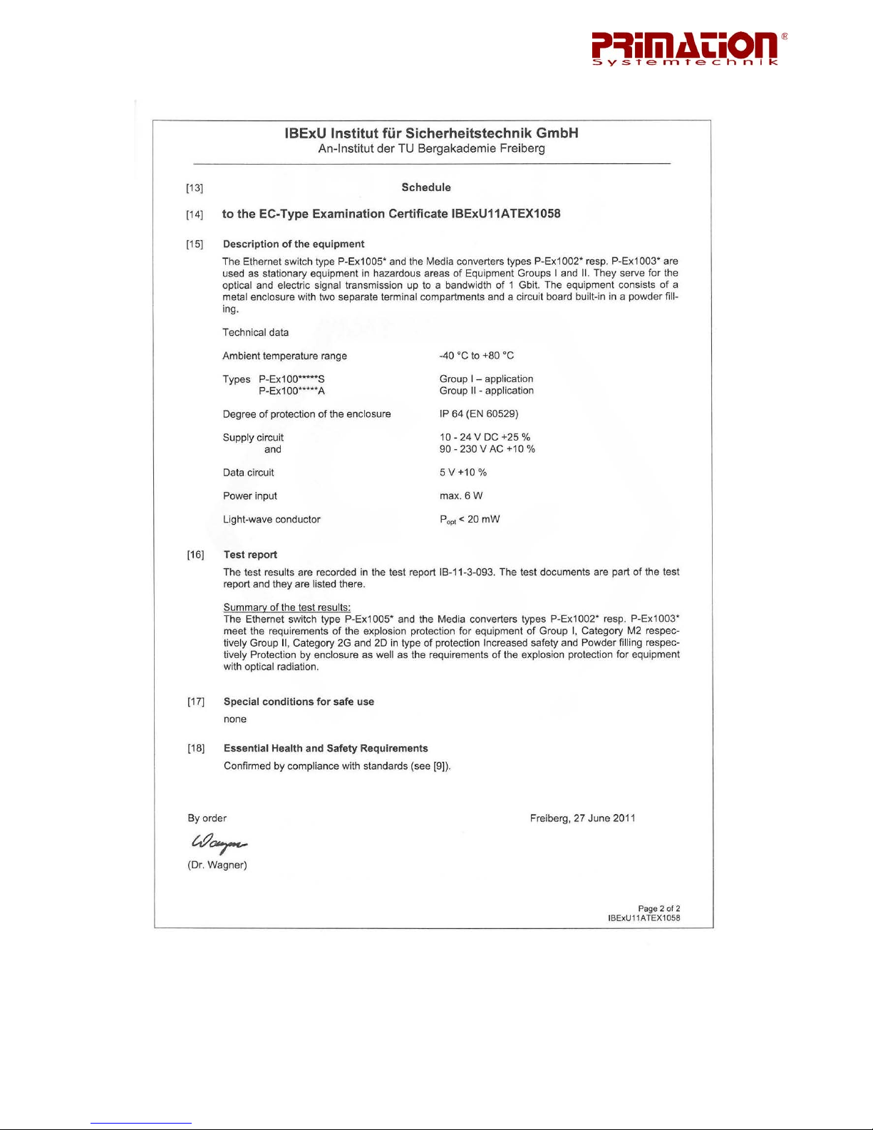
3.1 Explosionsschutz
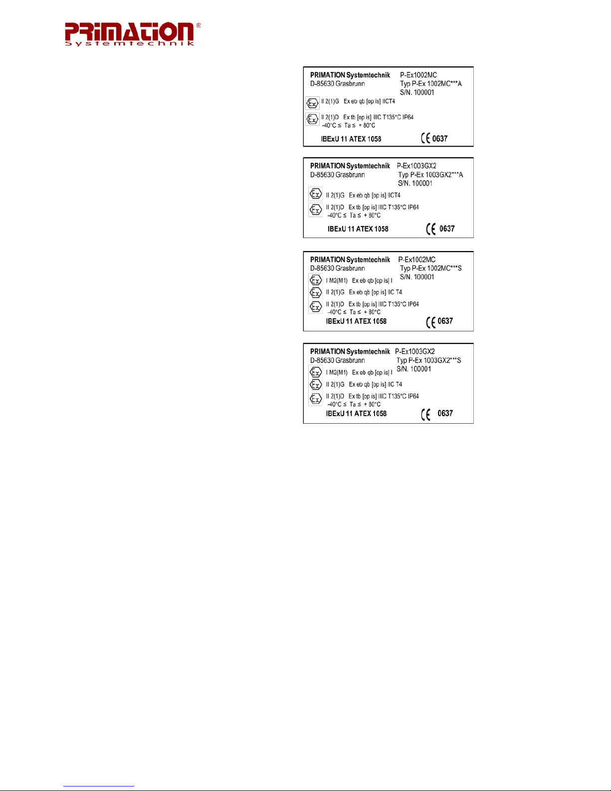
Typ: P-Ex1002MC
P-Ex1003GX2
P-Ex1005TX
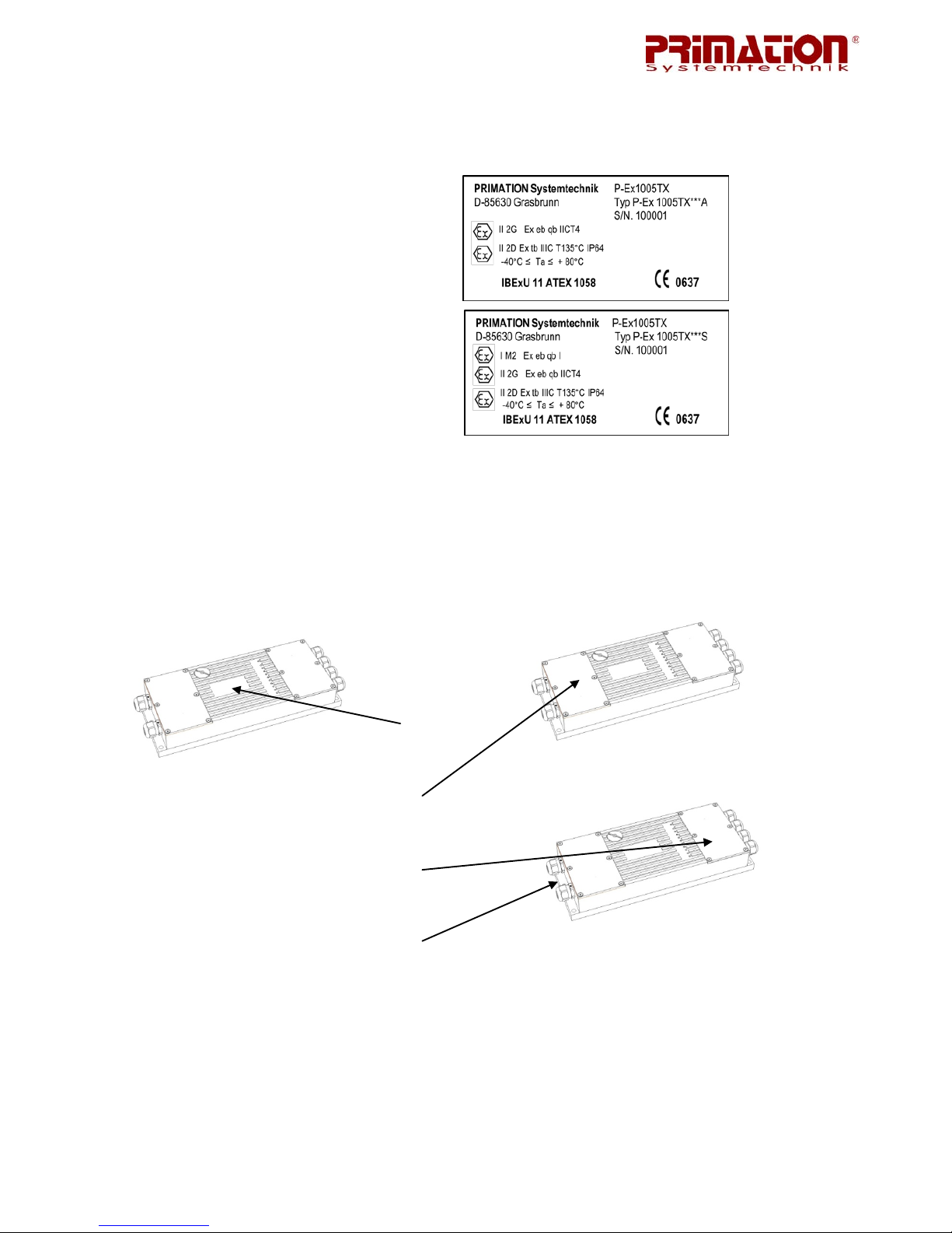
Kennzeichnung (Zone1): II 2G Ex eb qb IIC T4
II 2(1)G Ex eb qb [op is] IIC T4
Kennzeichnung (Zone21): II 2D Ex tb IIIC T135°C IP64
II 2(1)D Ex tb [op is] IIIC T135°C IP64
Kennzeichnung (Zone M2): I M2 Ex eb qb I
I M2 (M1) Ex eb qb [op is] I
Prüfbescheinigung: IBExU 11ATEX1058
weitere Daten siehe EG-Baumusterbescheinigung
3.2 Allgemeine Daten
Abmessungen (LxBxH): 350 x 140 x 53,3 mm
Betriebstemperatur: -40°C bis +80°C, 10 bis 90% relative Luftfeuchtigkeit,
nicht kondensierend
Lagertemperatur: -40°C bis +80°C, 10 bis 90% relative Luftfeuchtigkeit,
nicht kondensierend, außerhalb des explosionsgefähr deten Bereiches
Schutzart: IP 64 (EN 60529)
Gehäusematerial: Aluminium oder Edelstahl (V2A) für Mining M2
Masse: 4,5kg (Aluminium), 7,2kg (Edelstahl V2A)
3.3 Elektrische Daten
Spannungsversorgung: Typ P-Ex***DC Versorgung: DC-Versorgung redundant
Empfohlene Absicherung Nennspannung: +10V bis +24V DC +25%
1 AT Empfohlenes 24V DC Netzteil:
N-Tron NTPS-24-1.3, DC 24V/1,3A (o.ä.)
Typ P-Ex***AC Versorgung: Weitspannung
Nennspannung: 90V bis 230V AC +10%
Seite | 6
Leistungsaufnahme: P
max
≤ 6W
3.4 Ausgangsdaten
Max. Optische Leistung: P-Ex1002MC und P-Ex1003GX2 P
out
≤ 20mW
Max. Reichweite: P-Ex1*** Kupfer Cat5e Reichweite max. 100m
P-Ex1002/1003*** LWL "ST" Reichweite max. 550m
3.5 Produktkennzeichnung
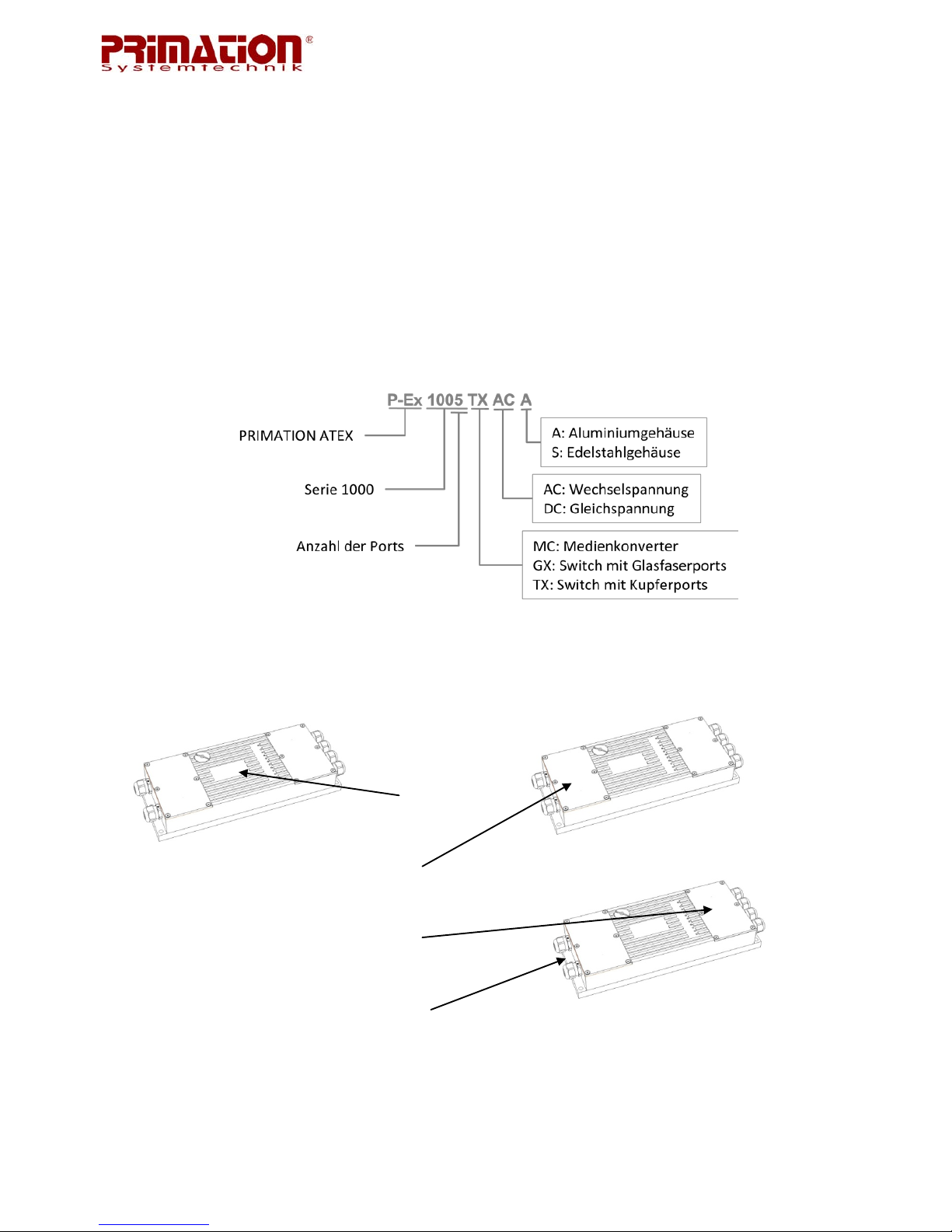
3.5.1 Typenschlüssel
3.5.2 P-Ex1005TX
A
B
C
D
Seite | 7
A Typschild Aluminiumgehäuse
Edelstahlgehäuse
B Anschlussraum Ex e Anschlussraum Klemme X1 bis X2
C Anschlussraum Ex e Anschlussraum Klemme X3 bis X7
D Klemme Potentialausgleichsleiter
3.5.3 P-Ex1002MC und 1003GX2
A
B
C
D
Seite | 8
A Typenschild Aluminiumgehäuse
Edelstahlgehäuse
B Anschlussraum Ex e Anschlussraum Klemme X1
C Anschlussraum Ex e Anschlussraum Klemme X2 bis X3
D Klemme Potentialausgleichsleiter
3.6 Angewandte Richtlinien und Normen
Richtlinie:
Für Geräte und Schutzsysteme zur bestimmungsgemäßen 94/9/EC
Verwendung in explosionsgefährdeten Bereichen.
RoHs 2002/95/EC
Normen für Explosionsschutz:
Elektr. Betriebsmittel für gasexplosionsgefährdete Bereiche:
Teil 0: Allgemeine Anforderungen EN 60 079-0: 2009
Elektr. Betriebsmittel für gasexplosionsgefährdete Bereiche:
Teil 5: Geräteschutz durch Sandkapselung "q" EN 60 079-5: 2007
Elektr. Betriebsmittel für gasexplosionsgefährdete Bereiche:
Teil 7: Geräteschutz durch erhöhte Sicherheit "e" EN 60 079-7: 2007

Seite | 9
Elektr. Betriebsmittel für gasexplosionsgefährdete Bereiche:
Teil 28: Schutz von Einrichtungen und Übertragungssystemen,
die mit optischer Strahlung arbeiten EN 60 079-28: 2007
Elektr. Betriebsmittel für gasexplosionsgefährdete Bereiche:
Teil 31: Geräte-Staubexplosionsschutz durch Gehäuse "t" EN 60 079-31: 2009
4 Montage
Achten Sie darauf, dass die Ethernet-Switches und Medienkonverter auf einem sicheren
Unterbau fest montiert werden. Der Montageort ist so zu wählen, dass eine Gefährdung des
Gerätes durch herabfallende Teile oder Stöße vermieden wird.
An den Ethernet-Switches und Medienkonvertern befinden sich an den Ecken vier Bohrungen zur Befestigung, somit muss das Gerät zur Montage nicht geöffnet werden.
4.1 Bohrplan

Seite | 10
5 Anschlussbelegung
5.1 Anschlussbelegung für P-Ex1002MC, P-Ex1003GX2, P-Ex1005TX
Klemmanschlussraum nicht unter Spannung öffnen!
5.1.1 Spannungsversorgung
Der Anschlussraum für die Spannungsversorgung ist ein Ex e Raum (Erhöhte Sicherheit).
Ex e Anschlussraum zur Spannungsversorgung für DC Modelle P-Ex1***-DC-*
Klemme: Bezeichnung:
X1 V1 +
X2 V1 X3 V2 +
X4 V2 X5 PE
Ex e Anschlussraum zur Spannungsversorgung für AC Modelle P-Ex1***-AC-*
Klemme: Bezeichnung:
X1 L
X2 nicht belegt
X3 N
X4 nicht belegt
X5 PE
• 0,2 - 2,5mm
2
/ 24AWG-16AWG Leiterquerschnitt flexibel
• 0,2 - 2,5mm
2 /
24AWG-16AWG Leiterquerschnitt starr
• max. 1 Leitung je Klemme
• Anzugsdrehmoment max. 0,5Nm

Seite | 11
5.1.2 Datenleitungen
Der Anschlussraum für die Datenleitungen ist ein Ex e Raum (erhöhte Sicherheit).
Ex e Anschlussraum für die Datenleitungen P-Ex1002MC, P-Ex1003GX2, P-Ex1005TX
Für die Kanäle 1 bis 5 (nur P-Ex1005TX) gilt folgende Belegung:
Klemme: Bezeichnung:
1 D0 +
2 D0 3 D1 +
4 D2 +
5 D2 6 D1 7 D3 +
8 D3 -
• 0,4 - 0,64mm
2
/ 26AWG-22AWG Leiterquerschnitt starr
• max. 1 Leitung je Klemme
• Das Kontaktieren der Kupferleiter erfolgt mit einem handelsüblichen LSA+ Anlege-
werkzeug
• Sicherungsbügel mit einem Drehmoment von 1,2Nm anziehen
Ex e Anschlussraum für die optischen Datenleitungen P-Ex1002MC und P-Ex1003GX2
Klemme: Bezeichnung:
1 RX Recieve Ch1
1 TX Transmit Ch1
2 RX Receive Ch2
2 TX Transmit Ch2
• Optische Schnittstellen mit vorkonfektionierten LWL-Kabeln verbinden
• Steckertyp ST
• Empfohlener Fasertyp: Multimode 50/125µm

Seite | 12
6 Inbetriebnahme
6.1 P-Ex1002MC, P-Ex1003GX2, P-Ex1005TX
Um eine einwandfreie Funktion und eine lange Lebensdauer der Geräte zu erhalten, ist es
notwendig auf eine sorgfältige Behandlung der Geräte zu achten. Im Kapitel 4 "Montage"
wird beschrieben wie Sie die Ethernet-Switches und Medienkonverter montieren müssen, um
z.B. Beschädigungen durch herunterfallende Teile zu vermeiden.
Benutzen Sie die Geräte nur in technisch einwandfreiem Zustand.
Bevor Sie den P-Ex1003MC, P-Ex1003GX2 oder den P-Ex1005TX zum ersten mal verwen-
den, müssen Sie diesen einwandfrei montiert und installiert haben (gemäß Kapitel 5 "Anschlussbelegung").
7 Funktionsweise P-Ex1002MC, P-Ex1003GX2, P-Ex1005TX
7.1 Vorderseite
P-Ex1002MC
P-Ex1003GX2

Seite | 13
P-Ex1005TX
7.2 Status-LEDs
Von oben nach unten:
POWER: Grüne LED leuchtet wenn die Spannungsversorgung hergestellt ist
LNK/ACT: Anzeige der Verbindung und Aktivität
SPD1000: Anzeige von 1000 Mbit/s Verbindungen
LEDs: Die Tabelle beschreibt die Funktionsweise
LED Zustand Beschreibung
POWER AN Spannungsversorgung hergestellt
AUS Keine Spannung sversorg ung
LNK/ACT AN Ver bindung herg estellt, keine Aktivität
BLINKEND Verbindung hergestellt, Aktivität
AUS Keine Verbindung hergestellt
SPD1000 AN Link mit 1000 Mbit/s
AUS Link mit 10/100 Mbit/s
7.3 Datenleitungen
Der Anschluss für 10 Mbit/s Ports muss mit einem Cat3 Kabel oder höherwertiger erfolgen.
Für den Anschluss von 100-1000 Mbit/s Ports muss ein Twisted Pair Kabel Cat5 oder höherwertig verwendet werden. Überprüfen Sie nach dem Herstellen der Verbindung, ob die
LINK LEDs leuchten. Um einen Port mit einem anderen Switch oder Router zu verbinden,
können Sie entweder ein Straight- oder Crossover-Kabel verwenden.
Achtung: Das Herstellen einer Port-zu-Port Verbindung auf dem selben Switch ist eine nicht
zulässige Verbindung. Dies würde einen Broadcast "Sturm" auslösen und das Netzwerk
funktionsunfähig machen.

Seite | 14
7.4 Fehlerbehebung
• vergewissern Sie sich, dass die POWER LED eingeschaltet ist
• stellen Sie sicher, dass Sie je nach gewähltem Modell die richtige Spannungsversor-
gung hergestellt haben.
Achtung: Der Einschaltstrom kann den Betriebsstrom um das doppelte übersteigen!
• stellen Sie sicher, dass die Link LEDs an beiden Ports leuchten
• überprüfen Sie die Verkabelung zwischen den beiden Ports
• vergewissern Sie sich, dass die Verkabelung für 10 Mbit/s mindestens Cat3 oder hö-
her ist.
7.5 Support
E-Mail: technik@primation.de
Telefon: +49 (0)89 46 26 0 - 0
8 Zusatzinformationen
8.1 Links
http://www.primation.de Webseite PRIMATION Systemtechnik
http://www.primation.de/de_atex.html ATEX Produktwebseite
http://www.n-tron.com Webseite N-TRO N Corp .
8.2 Informationen rund um den Explosionsschutz
Hersteller explosionsgeschützter Systeme, Geräte und Komponenten, Errichter und Betreiber von Anlagen schaffen gemeinsam die Voraussetzungen für den sicheren Betrieb von
Anlagen in explosionsgefährdeten Bereichen. Beim Betreiber ist das W issen der Mitarbeiter
um die Zusammenhänge des Explosionsschutzes und um die getroffenen Maßnahme, die zu
ihrer Vermeidung angewendet werden, eine wichtige Voraussetzung dafür.
Über den Inhalt des Explosionsschutzdokumentes nach Richtlinie 1999/92/EG (in der Bundesrepublik umgesetzt in der Betriebssicherheitsverordnung BetrSichV) und die betrieblich
geltenden Regelungen, sollten die Mitarbeiter r egelmäßig geschult und mit schriftlichen Betriebsanweisung informiert werden. Eine Kontrolle dieser Maßnahmen muss ebenfalls regelmäßig erfolgen.
Baubestimmungen für explosionsgeschützte Systeme, Geräte und Komponenten Betriebsmittel
Gefahren, die beim Umgang mit brennbaren Gasen, Dämpfen und Stäuben auftreten, beruhen auf einheitlichen chemischen und physikalischen Abläufen. Deshalb kann auch die Abwehr dieser Gefahren nur einheitlich erfolgen.

Seite | 15
In der Internationalen Elektrotechnischen Kommission IEC, in den Europäischen Normengremien CENELEC und CEN sowie in DKE und DIN sind inzwischen nahezu durchgängig einheitliche Forderungen formuliert.
Die Einhaltung wird von den Herstellern und Betreibern gefordert und bei erhöhten Schutzanforderungen von anerkannten Prüfstellen und Behörden überwacht.
9 Versand und Verpackungshinweis
Wichtiger Hinweis zum Transport und Versand
Empfindliche Geräte !
Es ist unbedingt erforderlich das Gerät in der Originalverpackung zu versenden, um
Beschädigungen am Gerät zu vermeiden.

Seite | 15
10 Prüfbescheinigungen
10.1 EG-Konformitätserklärung

Seite | 16
10.2 EG-Baumusterprüfbescheinigung IBExU 11 ATEX 1058

Seite | 17


Ethernet Switches and Media Converters
Model
P-Ex 1002MC
Model
P-Ex 1003GX2
Model
P-Ex 1005TX
ATEX Version
Zone 1 / 21 / M2
Version: 1.03
Document No. EX-11-200001
Last updated: 15
th
May 2012
Subject to technical changes
Contents
Page
German 1 - 17
English 18 - 35
PRIMATION Systemtechnik Tel.: +49 (0)89 46 26 0 - 0
GmbH & Co. KG Fax: +49 (0)89 46 26 0 - 210
Bretonischer Ring 13 E-mail: info@primation.de
85630 Grasbrunn Web: http://www.primation.de
Germany
User Manual

Before commissioning
Please read the operating instructions carefully and in full!
Target group:
Experienced specialists in compliance with the Directives 99/92/EC, IEC 60079-19 and EN
60079-17.
Please note:
This user manual contains important information, safety instructions and test certification,
which are necessary for error-free functioning during the operation and handling of the
Ethernet switches and media converters. If the information and safety instructions are not
followed, the intended usage in potentially explosive areas is not guaranteed.
Changes to the devices which have not been expressly approved by PRIMATION Systemtechnik GmbH & Co. KG (PRIMATION), will result in the forfeit of the operating perm it for
the device in question. Non-compliance will result in the forfeit of claims under warranty. The
warranty will be forfeited if damage occurs to the product as the result of inappropriate handling, excessive loading, inadequate maintenance, abnormal operating conditions or
transport damage. Natural wear and tear is also excluded from the warranty.
PRIMATION reserves the right to make changes to the content of this document without prior
notice. The accuracy of the information is therefore not guaranteed. In case of doubt, the
German safety instructions take precedence, as translation and printing errors cannot be
ruled out. In the case of a legal dispute, the "General Terms and Conditions" of PRIMATION
shall also apply.
The current versions of the data sheets, manuals, certificates and the EC Declaration of Conformity can be downloaded from the "ATEX" product page at www.primation.de or requested
directly from PRIMATION.
Documentation
The documents are available in German and English.
Visit our website http://www.primation.de for information about your specific product.


Pictograms and Safety Information
Indicates risk of injury or death if particular rules are not followed. Please observe all
safety precautions indicated with this pictogram.
Indicates a potentially dangerous situation which could lead to material damage if
the situation is not avoided.
Indicates useful tips, recommendations and information for efficient, environmentally
friendly and error-free operation.

Contents
1 Product Description .......................................................................................................18
1.1 General ..................................................................................................................18
1.2 Advantages ............................................................................................................18
1.3 Package Contents ..................................................................................................19
2 Safety Information .........................................................................................................19
2.1 Warnings for Ethernet switches and media converters ...........................................19
2.2 Warnings for Laser Devices ...................................................................................20
2.3 Installation Instructions ...........................................................................................20
2.3.1 Installation Guidelines .....................................................................................20
2.4 Maintenance ..........................................................................................................21
2.4.1 Maintenance ...................................................................................................21
2.4.2 Repair Information ...........................................................................................21
2.4.3 Inspection ........................................................................................................21
2.4.4 Repairs ...........................................................................................................21
2.5 Health and Safety Recommendations ....................................................................21
3 Technical Data ..............................................................................................................22
3.1 Blast proofing .........................................................................................................22
3.2 General Data ..........................................................................................................22
3.3 Electrical Data ........................................................................................................22
3.4 Output Data ............................................................................................................23
3.5 Product Designation ...............................................................................................23
3.5.1 Type Code ......................................................................................................23
3.5.2 P-Ex1005TX ....................................................................................................23
3.5.3 P-Ex1002MC and 1003GX2 ............................................................................24
3.6 Applicable Directives and Standards ......................................................................25
4 Assembly ......................................................................................................................26
4.1 Hole Plan ...............................................................................................................26
5 Terminal Assignment .....................................................................................................27
5.1 Terminal assignment for P-Ex1002MC, P-Ex1003GX2, P-Ex1005TX ....................27
5.1.1 Power Supply ..................................................................................................27
5.1.2 Data Lines .......................................................................................................28
6 Commissioning ..............................................................................................................29
6.1 P-Ex1002MC, P-Ex1003GX2, P-Ex1005TX ...........................................................29
7 P-Ex1002MC, P-Ex1003GX2, P-Ex1005TX functions ...................................................29
7.1 Front Side ..............................................................................................................29

7.2 Status LEDs ...........................................................................................................30
7.3 Data Lines ..............................................................................................................30
7.4 Troubleshooting .....................................................................................................31
7.5 Support ..................................................................................................................31
8 Additional Information ....................................................................................................31
8.1 Links ......................................................................................................................31
8.2 Information about Blast Proofing ............................................................................31
9 Shipping and Packaging Information .............................................................................32
10 Test Certificates .........................................................................................................33
10.1 EC Declarat ion of Co nformity .................................................................................33
10.2 EC Type Examination Certificate IBExU 11 ATEX 1058 .........................................34


Page | 18
1 P roduct Description
1.1 General
The Ethernet switches and P-Ex1002MC, P-Ex1003GX2 and P-Ex1005TX media converters
are used as stationary devices in potentially explosive areas for device groups I and II. They
are used to transmit optical or electrical data signals up to a bandwidth of 1 Gbit/s.
The products are available in two different versions, with aluminum housing for use in zone 1
and zone 21 and with stainless steel housing for use in mining zone M2.
1.2 Advantages
• Aluminum or stainless steel housing
• Direct assembly in ATEX zone 1 and 21 and M2
• No additional power supply is required
• Connection of further devices possible with simple equipment
• 5 Port gigabit switch and 3 Port TX/FX switch with identical housing
• IEEE 802.3
• Jumbo frame support
• Operating and storage temperature of -40°C to +80°C
• Supports full/half duplex
• Data throughput of up to 10Gb/s
• Store-and-forward technology
• LED link/activity status indicators
Figure 1: P-Ex 1005TX

Page | 19
1.3 Package Contents
Please ensure that the package contains the following parts:
1. P-Ex1002MC, P-Ex1003GX2 or P-Ex1005TX
2. User manual
2 Safety Information
2.1 Warnings for Ethernet switches and media converters
• The switches and media converters are to be installed only in approved potentially explosive areas for device categories I and II and in zones M2, 1 and 21.
• Ensure that the power is switched off during installation.
• The device must not be opened outside of the potentially explosive area! Chang-
es must not be made to the device.
• Components must not be exchanged or replaced. If components other than those
specified are used, blast proofing is no longer guaranteed.
This device is sealed at the factory. Do not open the device!
• Do not open the terminal compartment when the power is switched on.
• The equipotential bonding connector must be connected to the equipotential
bonding conductor for the potent ially explosive area. As the intrinsically safe circuits are galvanically connected to ground, equipotential bonding must exist
throughout the installation of the intrinsically safe circuits.
• Protect the device from knocks and do not expose it to any corrosive/aggressive
fluids, steams or mists. In the event of malfunctions or damage to the housing,
the device must immediately be removed from the potentially explosive area.
• The device must immediately be put out of operation if it is suspected that the
operating equipment can no longer be operated safely after harmful influences or
in the event of general problems (e.g. penetration of water or fluids, effect of
temperatures outside the specified range, etc.)
• General legal regulations or guidelines regarding safety at work, accident prevention regulations and environmental protection laws must be followed, e.g. Betriebssicherheitsverordnung (BetrSichV, industrial safety act) or applicable national laws.
• For electrical systems, the relevant installation and operating regulations must be
followed.
• The rules for potentially explosive areas (Directive 99/92/EC) must be followed.
Prevent hazardous electrostatic charging by wearing suitable clothing and shoes.
Do not use rubber gloves or such like!

Page | 20
• Avoid exposure to heat outside of the specified temperature range (see section
3.2 "General Data"). Do not place the device close to sources of heat such as
heaters, air outlets of air conditioning systems, cookers or other devices (including amplifiers) which emit heat.
• Avoid exposure to moisture.
• Do not insert any objects into the housing or other openings of the P-Ex1002MC,
P-Ex1003GX2 and P-Ex1005TX. Openings on the device must not be blocked,
closed or covered.
• Before commissioning the device, ensure that it has been installed in accordance
with the regulations.
2.2 Warnings for Laser Devices
Under normal conditions, the class I laser works at a power beneath the eye safety thres hold. If the eye safety threshold is exceeded, a laser er ror will occur and the TX_FAULT output will be activated.
2.3 Installation Instructions
• The switches and media converters are to be installed only in approved potentially explosive areas for device categories I and II and in zones M2, 1 and 21.
• Ensure that the power is switched off during installation.
• For electrical systems, the relevant installation and operating regulations must be
followed (e.g. Directives 99/92/EC, 94/9/EC, BetrSichV or applicable national
laws, IEC 60 079-14 and the VDE 0100 series)
• The operator of an electrical system in a potentially explosive environment must
keep the equipment in a satisfactory condition and must operate and monitor the
equipment properly, as well as performing maintenance and repair work.
The device is sealed at the factory. Do not open the device!
The device may only be opened in the factory!
2.3.1 Installation Guidelines
The safety and accident prevention regulations that are applicable in each individual case
must be followed. Devices must only be operated in a fully assembled state.
• The equipotential bonding connector must be connected to the equipotential
bonding conductor for the potentially explosive area. As the intr insically safe circuits are galvanically connected to ground, equipotential bonding must exist
throughout the installation of the intrins ic a lly safe circuits.
• It must be possible to switch off the power supply to the products at any time (in
the case of a fixed connection via an all-pole disconnector or fuse)

Page | 21
2.4 Maintenance
For the repair, maintenance and inspection of associated operating equipment, follow the
applicable regulations as well as Directives 99/92/EC, IEC 60079-19 and IEC 60079-17!
Assembly/dismantling and operating and maintenance work may only be performed by
trained specialist personnel. Legal regulations and other binding guidelines regarding safety
at work, accident prevention and environmental protection must be followed.
When disposing of the device, follow the national waste disposal regulations.
2.4.1 Maintenance
If correctly operated in compliance with the assembly instructions and cor rect environmental
conditions, no regular maintenance is required.
2.4.2 Repair Information
If you would like to send us a defective device for repair, please contact us.
E-mail: service@primation.de
Telephone: +49 (0)89 46 26 0 - 0
Please specify the serial number of the device to be repaired.
2.4.3 Inspection
In accordance with IEC 60079-19 and IEC 60079-17, the operator of electrical systems in
potentially explosive areas must have these systems inspected by a qualified electrician to
ensure that they are in a satisfactory condition.
2.4.4 Repairs
Repairs to blast-proofed operating equipment may only be performed by persons authorized
to do so using original spare parts and the most recent technology. The applicable regulations must be followed. If you have any queries, please contact PRI MATION Systemtechnik
GmbH & Co. KG.
2.5 Health and Safety Recommendations
All components must be dry before being connected to an external power supply.

Page | 22
3 Technical Data
3.1 Blast proofing
Model: P-Ex1002MC
P-Ex1003GX2
P-Ex1005TX
Designation (Zone1): II 2G Ex eb qb IIC T4
II 2(1)G Ex eb qb [op is] IIC T4
Designation (Zone21): II 2D Ex tb IIIC T135°C IP64
II 2(1)D Ex tb [op is] IIIC T135°C IP64
Designation (Zone M2): I M2 Ex eb qb I
I M2 (M1) Ex eb qb [op is] I
Test certification: IBExU 11ATEX1058
for further data, see EC Type Examination Certificate
3.2 General Data
Dimensions (WxDxH): 350 x 140 x 53.3 mm
Operating temperature: -40°C to +80°C, 10 to 90% relative humidity,
non-condensing
Storage temperature: -40°C to +80°C, 10 to 90% relative humidity,
non-condensing, outside of potentially explosive area
Protection class: IP 64 (EN 60529)
Housing material: Aluminum or stainless steel (V2A) for mining M2
Mass: 4. 5kg (aluminum), 7.2kg (stainless steel V2A)
3.3 Electrical Data
Power supply: Model P-Ex***DC Power supply: DC supply redundant
Recommended fuse Nominal voltage: +10V to +24V DC +25%
1 AT Recommended 24V DC power supply unit:
N-Tron NTPS-24-1.3, DC 24V/1.3A (or similar)
Model P-Ex***AC Power supply: Wide-range voltage
Nominal voltage: 90V to 230V AC +10%
Power consumption: P
max
≤ 6W

Page | 23
3.4 Output Data
Max. optical power: P-Ex1002MC and P-Ex1003GX2 P
out
≤ 20mW
Max. operating range:
P-Ex1*** Copper Cat5e Max. operating range 100m
P-Ex1002/1003*** Optical fiber "ST" Max. operating range 550m
3.5 Product Designation
3.5.1 Type Code
3.5.2 P-Ex1005TX
A
B
C
D

Page | 24
A Type plate Aluminum housing
Stainless steel housing
B Terminal compartment Ex e Terminal compartment terminals X1 to X2
C Terminal compartment Ex e Terminal compartment terminals X3 to X7
D Terminal Equipotential bonding conductor
3.5.3 P-Ex1002MC and 1003GX2
A
B
C
D

Page | 25
A Type plate Aluminum housing
Stainless steel housing
B Terminal compartment Ex e Terminal compartment terminal X1
C Terminal compartment Ex e Terminal compartment terminals X2 to X3
D Terminal Equipotential bonding conductor
3.6 Applicable Directives and Standards
Directive:
For devices and protective systems for intended 94/9/EC
use in potentially explosive areas.
RoHs 2002/95/EC
Standards for explosion protection:
Electr. operating equipment for areas at risk of gas explosion:
Part 0: General requirements EN 60 079-0: 2009
Electr. operating equipment for areas at risk of gas explosion:
Part 5: Equipment protection through sand filling "q" EN 60 079-5: 2007
Electr. operating equipment for areas at risk of gas explosion:
Part 7: Equipment protection through increased safety "e" EN 60 079-7: 2007

Page | 26
Electr. operating equipment for areas at risk of gas explosion:
Part 28: Protection of equipment and transfer systems
which work with optical radiation EN 60 079-28: 2007
Electr. operating equipment for areas at risk of gas explosion:
Part 31: Protection against dust explosion through housing "t" EN 60 079-31: 2009
4 Assembly
Ensure that the Ethernet switches and media converters are securely assembled on a secure
supporting structure. The assembly location must be chosen so that t he device is not at risk
from falling parts or knocks.
On the Ethernet switches and media converters there are, in the corners, four holes for fastening, so the device does not have to be opened for assembly.
4.1 Hole Plan
Figure 2

Page | 27
5 Terminal Assignment
5.1 Terminal assignment for P-Ex1002MC, P-Ex1003GX2, P-Ex1005TX
Do not open the terminal compartment when the power is switched on.
5.1.1 Power Supply
The terminal compartment for the power supply is an Ex e compartment (increased safety).
Figure 3
Ex e terminal compartment for power supply for DC models P-Ex1***-DC-*
Terminal: Designation:
X1 V1 +
X2 V1 X3 V2 +
X4 V2 X5 PE
Ex e terminal compartment for power supply for AC models P-Ex1***-AC-*
Terminal: Designation:
X1 L
X2 not as signed
X3 N
X4 not as signed
X5 PE
• 0.2 - 2.5mm
2
/ 24AWG-16AWG conductor cross section, flexible
• 0.2 - 2.5mm
2
/ 24AWG-16AWG conductor cross section, rigid
• Max. 1 line per terminal
• Tightening torque max. 0.5Nm
Figure 4
Figure 5

Page | 28
5.1.2 Data Lines
The terminal compartment for the data lines is an Ex e compartment (increased safety).
Figure 6
Ex e terminal compartment for the P-Ex1002MC, P-Ex1003GX2, P-Ex1005TX data lines
For channels 1 to 5 (P-Ex1005TX only), the following assignment applies:
Terminal: Designation:
1 D0 +
2 D0 3 D1 +
4 D2 +
5 D2 6 D1 7 D3 +
8 D3 -
• 0.4 - 0.64mm
2
/ 26AWG-22AWG conductor cross section, rigid
• Max. 1 line per terminal
• The contacting of the copper conductors is done using a conventional LSA+ punch
down tool
• Tighten the retaining clip with a torque of 1.2Nm
Ex e terminal compartment for the P-Ex1002MC and P-Ex1003GX2 optical data lines
Terminal: Designation:
1 RX Receive Ch1
1 TX Transmit Ch1
2 RX Receive Ch2
2 TX Transmit Ch2
• Connect the optical interfaces using prefabricated optical fiber cables
• Plug type ST
• Recommended fiber type: Multimode 50/125µm
Figure 7
Figure 8

Page | 29
6 Commissioning
6.1 P-Ex1002MC, P-Ex1003GX2, P-Ex1005TX
In order to achieve perfect functioning and a long service lif e for the devices, it is necessary
to ensure careful handling of the devices. Section 4 "Assembly" describes how the Ethernet
switches and media converters must be assembled in order to avoid damage from falling
parts.
The devices must only be used in perfect technical condition.
Before using the P-Ex1003MC, P-Ex1003GX2 or P-Ex1005TX for the first time, they m ust
have been correctly assembled and installed (in accordance with section 5 "Terminal Assignment").
7 P-Ex1002MC, P-Ex1003GX2, P-Ex1005TX functions
7.1 Front Side
P-Ex1002MC
P-Ex1003GX2
Figure 9
Figure 10

Page | 30
P-Ex1005TX
7.2 Status LEDs
From top to bottom:
POWER: Green LED lights up when the power supply is established
LNK/ACT: Indicates connection and activity
SPD1000: Indicat es 1000 Mbit/s connections
LEDs: The table describes the functions
LED Status Description
POWER ON Power supply established
OFF No power supply
LNK/ACT ON Connection established, no activity
FLASHING Connection established, activity
OFF No connection established
SPD1000 ON Link with 1000 Mbit/s
OFF Link with 10/100 Mbit/s
7.3 Data Lines
The connection for 10 Mbit/s ports must be made with a Cat3 cable or higher. For the connection of 100-1000 Mbit/s ports, a twisted pair cable of Cat5 or higher must be used. After
establishing the connection, check whether the LINK LEDs are lit up. In order to connect a
port with another switch or router, either a straight or crossover cable can be used.
Note: Establishing a port-to-port connection on the sam e switch is not permitted. This would
cause a broadcast "storm" and make the network inoperable.
Figure 11

Page | 31
7.4 Troubleshooting
• Ensure that the POWER LED is on
• Ensure that the correct power supply has been established for the chosen model.
Note: The start-up current may be twice as great as the operating current!
• Ensure that the link LEDs on both ports are lit up
• Check the wiring between both ports
• Ensure that the wiring for 10 Mbit/s is at least Cat3 or higher.
7.5 Support
E-mail: technik@primation.de
Telephone: +49 (0)89 46 26 0 - 0
8 Additional Information
8.1 Links
http://www.primation.de PRIMATION Systemtechnik website
http://www.primation.de/de_atex.html ATEX Product website
http://www.n-tron.com N-TRON Corp. website
8.2 Information about Blast Proofing
Manufacturers of explosion-protected systems, devices and components and installers and
operators of systems are together responsible for fulfilling the prerequisi tes for safe operation
of systems in potentially explosive areas. It is important that the operator should ensure that
their employees know how the danger of explosions is likely to arise and the measures that
are taken to avert it.
Employees should receive regular training and written instructions regarding the content of
the blast proofing document in accordance with Directive 1999/92/EC (implemented in the
Federal Republic of Germany as the Betriebssicherheitsverordnung BetrSichV) and the applicable operational regulations. Regular checks of these measures must also be carried out.
Building regulations for blast-proofed systems, devices and components - operating
equipment
Hazards which occur during the handling of flammable gases, steams and dusts are based
on uniform chemical and physical processes. Therefore, the prevention of these hazards
must also always be uniform.
Almost entirely uniform requirements have now been formulated by the International Electrotechnical Commission (IEC), the European standardization committees CENELEC and CEN
as well as DKE and DIN.
Compliance by manufacturers and operators is required and, in cases of increased protection requirements, monitored by approved testing organizations and authorities.

Page | 32
9 Shipping and Packaging Information
Important information about transport and shipping
Sensitive equipment!
It is absolutely essential to ship the device in its original packaging in order to avoid
damage to the device.

Page | 33
10 Test Certificates
10.1 EC Declaration of Conformity

Page | 34
10.2 EC Type Examination Certificate IBExU 11 ATEX 1058
Page | 35
 Loading...