

Page 1
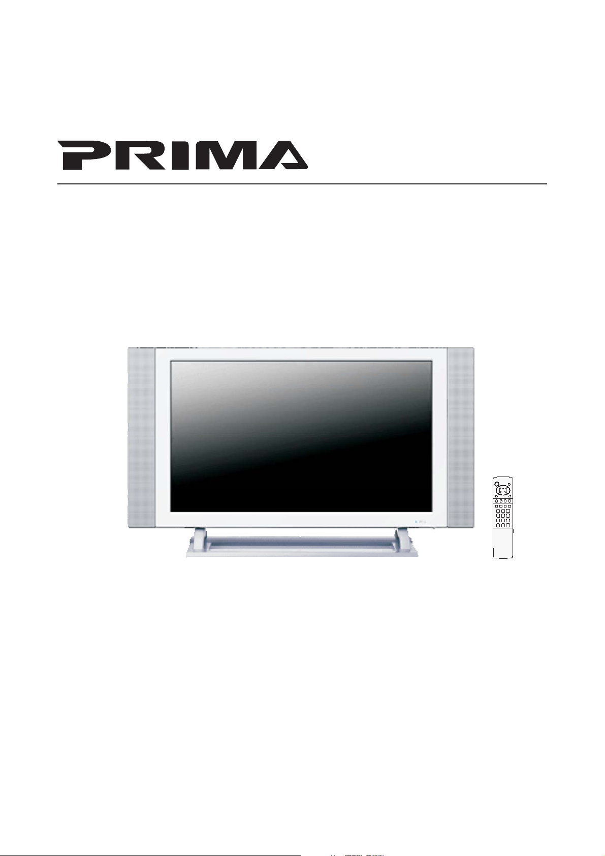
PDP TV
Operating Manual
Before connecting, operating or adjusting this product, please read the manual
Page 2

Table of Contents
Important Information....................................................................................................1
Important Safety Precautions..........................................................................................2
Preparations...................................................................................................................5
Using the Remote Control .......................................................................................5
Batteries for the Remote Control .............................................................................5
Power connection ....................................................................................................6
Speaker connection .................................................................................................6
Antenna Connection................................................................................................7
Identification of Controls ...............................................................................................8
Main unit (front view) ..............................................................................................8
Main unit (rear view)................................................................................................9
Remote Control ......................................................................................................
10
Connections..................................................................................................................
12
Cautions before connecting....................................................................................
12
Connect a VCR .......................................................................................................
12
Connect a Camcorder .............................................................................................
13
Connect a DVD player.............................................................................................
14
Connect a DTV receiver ..........................................................................................
15
Connect a PC..........................................................................................................
16
Connect a VCR (for recording) or external amplifier................................................
17
Turning the Unit On and Off..........................................................................................
18
Memorizing the Channels..............................................................................................
19
Selecting the Signal Source.....................................................................................
19
Storing Channels in Memory Automatically.............................................................
19
Setting Auto Fine Tune (AFT) ..................................................................................
20
Manual Fine Tuning................................................................................................
20
Adding and Erasing Channels .................................................................................
20
Basic Operations ...........................................................................................................
21
Changing Channels ................................................................................................
21
Adjusting the Volume.............................................................................................
21
Page 3

Table of Contents
Setting Sound ...............................................................................................................
28
Using the Preset Audio Mode .................................................................................
28
Customizing the Sound..........................................................................................
28
Adjusting the Headphone Volume ..........................................................................
28
Choosing a Multi-Channel Sound (MTS) Soundtrack ................................................
29
Using the Auto Volume ..........................................................................................
29
Changing Screen Layout ...............................................................................................
30
Selecting Screen Layout..........................................................................................
30
PIP .........................................................................................................................
31
Split Screen ............................................................................................................
31
POP3......................................................................................................................
31
Grid .......................................................................................................................
31
PIP Operations ..............................................................................................................
32
Viewing the Picture-in-Picture.................................................................................
32
Adjusting the Size of PIP Frame .............................................................................
32
Changing the Position of the PIP Frame ..................................................................
33
Adjustment in PC (VGA) Mode.......................................................................................
34
Adjusting Picture ..................................................................................................
34
Adjusting the Phase and Frequency........................................................................
Page 4
Important Information
WARNING:
CAUTION-To reduce the risk of electric shock, do
"Note to CATV system installer: This reminder is provided to call the CATV system installer's attention to
Article 820-40 of the National Electrical Code that provides guidelines for proper grounding and, in
particular, specifies that the cable ground shall be connected to the grounding system of the building, as
TO REDUCE THE RISK OF FIRE OR ELECTRIC SHOCK, DO NOT EXPOSE THIS APPARATUS TO
RAIN OR MOISTURE.
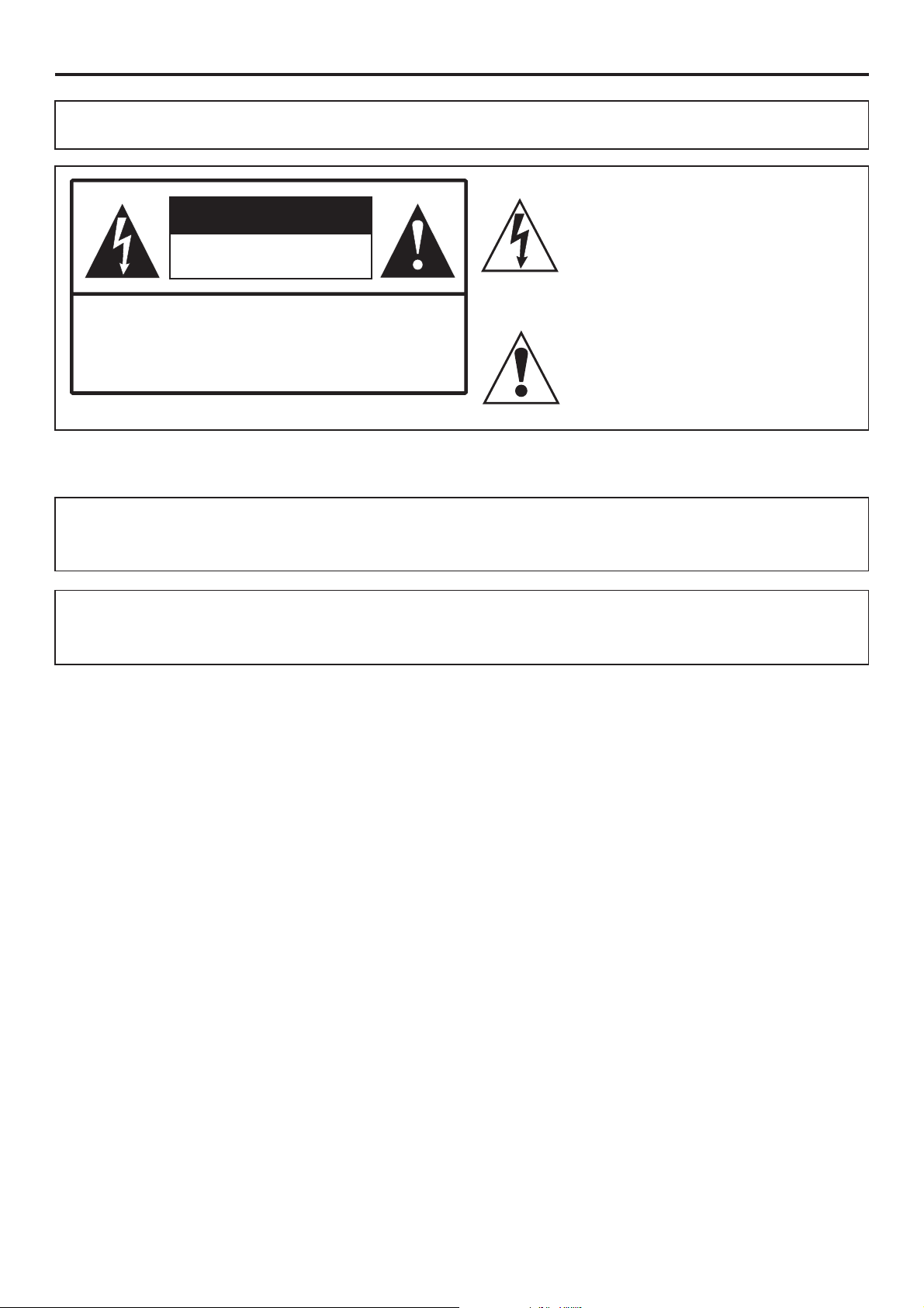
The lightning flash with arrowhead
CAUTION
RISK OF ELECTRIC SHOCK
DO NOT OPEN
not perform any servicing other than that
contained in the operating instructions
unless you are qualified to do so.
symbol,
within an equilateral triangle is
intended to
alert the user to the presence of
uninsulated
The exclamation point within an
equilateral
triangle is intended to alert the user to
the
presence of important operating and
This product utilizes tin-lead solder, and fluorescent lamp containing a small amount of mercury. Disposal of
these materials may be regulated due to environmental considerations. For disposal or recycling
information, please contact your local authorities or the Electronic Industries Alliance: www.eia.org
FCC STATEMENT
FCC Notice
PDP TV: A CLASS B digital device
This equipment has been tested and found to comply with the limits for a Class B digital device,
pursuant to part 15 of the FCC Rules. These limits are designed to provide reasonable protection
against harmful interference when the equipment is operated in a commercial environment.
This equipment generates, uses, and can radiate radio frequency energy and, if not installed and used
in accordance with the instruction manual, may cause harmful interference to radio communications.
Operation of this equipment in a residential area is likely to cause harmful interference in which case the
user will be required to correct the interference at his own expense.
FCC CAUTION:
Pursuant to 47CFR, Part 15.21 of the FCC rules, any changes or modifications to this monitor not expressly
approved by the manufacturer could cause harmful interference and would void the user's authority to
WARNING: This is a CLASS B product. In a domestic environment this product may cause
radio interference in which case the user may be required to take adequate
1
Page 5
Important Safety Precautions
Electrical energy can perform many useful functions, but it can also cause personal injuries and
property damage if improperly handled. This product has been engineered and manufactured with the
highest priority on safety. But IMPROPER USE CAN RESULT IN POTENTIAL ELECTRICAL SHOCK OR FIRE
HAZARD. In order to prevent potential danger, please observe the following instructions when
installing, operating and cleaning the product. To ensure your safety and prolong the service life of your
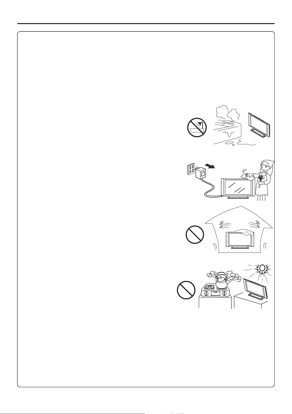
5. Do not use this apparatus near water---for example, near a
bathtub, washbowl, kitchen sink, or laundry tub, in a wet
basement, or near a swimming pool, and the like.
Do not use immediately after moving from a low temperature to
high temperature environment, as this causes condensation,
which may result in fire, electric shock, or other hazards.
6. Clean only with dry cloth---Unplug this product from the wall
outlet before cleaning. Do not use liquid cleaners or aerosol
cleaners. Use a damp cloth for cleaning.
7. Do not block any ventilation openings. Install in
Ventilation---
accordance with the manufacturer instructions. The vents and
other openings in the cabinet are designed for ventilation. Do not
cover or block these vents and openings since insufficient
ventilation can cause overheating and/or shorten the life of the
product. Do not place the product on a bed, sofa, rug or other
similar surface, since they can block ventilation openings. This
product is not designed for built-in installation; do not place the
product in an enclosed place such as a bookcase or rack, unless
8.Heat sources---Do not install near any heat sources such as
radiators, heat registers, stoves, or other apparatus (including
9.Grounding or Polarization---Do not defeat the safety purpose of the polarized or grounding-type plug.
A polarized plug has two blades with one wider than the other. A grounding type plug has two blades
and a third grounding prong. The wide blade or the third prong are provided for your safety. If the
provided plug does not fit into your outlet, consult an electrician for replacement of the obsolete outlet.
10.Power cord protection---Protect the power cord from being walked on or pinched particularly at
plugs, convenience receptacles, and the point where they exit from the apparatus.
11. Only use attachments/accessories specified by the manufacturer. Do not use
Attachments---
attachments not recommended by the manufacturer. Use of improper attachments can result in
2
Page 6
Important Safety Precautions (continued)
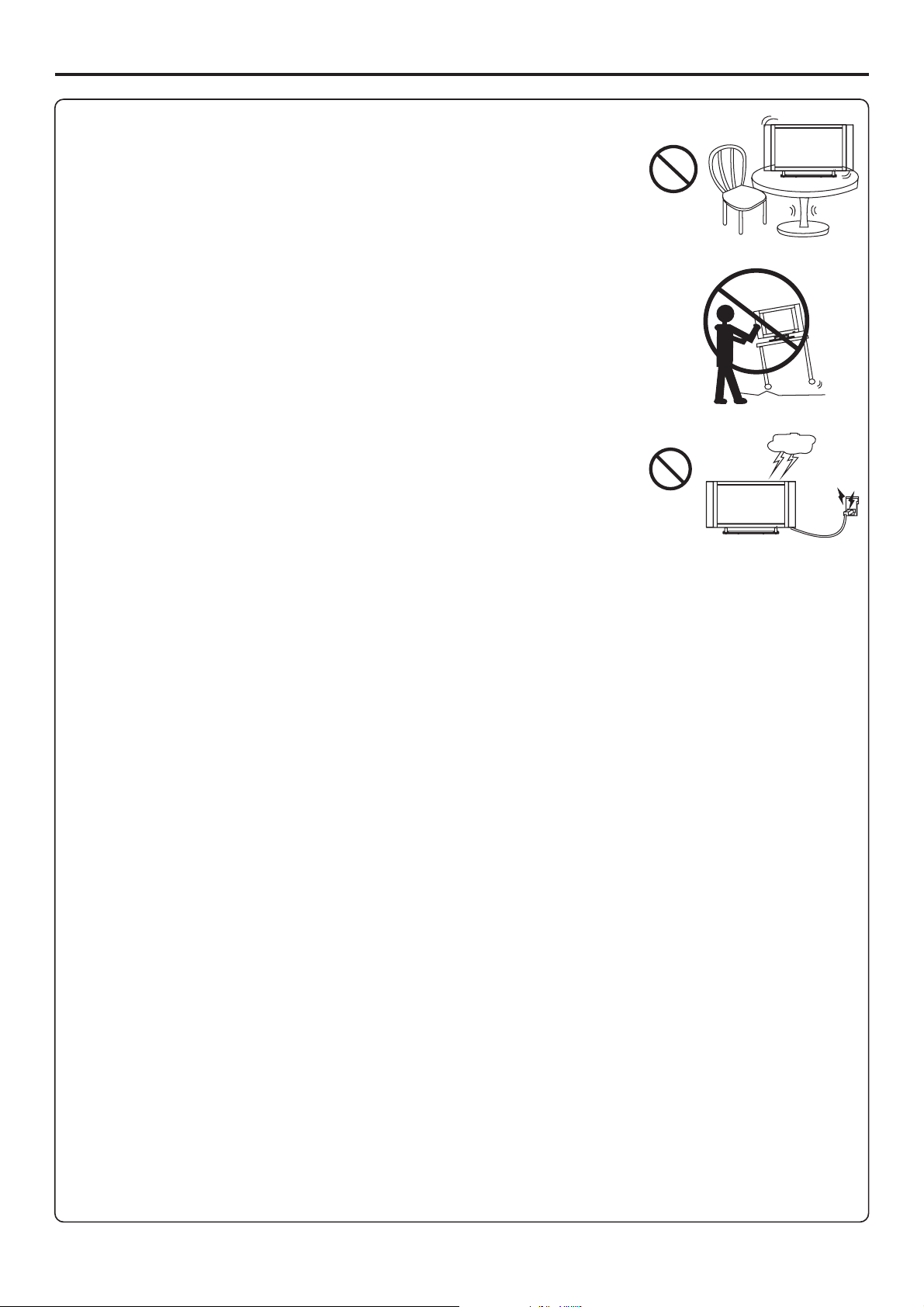
12. Stand Use only with the cart, stand, tripod, bracket, or table specified
by the manufacturer, or sold with the apparatus. Do not place the product
on an unstable trolley, stand, tripod or table. Placing the product on an
unstable base can cause the product to fall, resulting inserious personal
injuries as well as damage to the product. When mounting the product on
a wall, be sure to follow the manufacturer’s instructions. Use only the
13. When a cart is used, use caution when moving the
cart/apparatus combination to avoid injury from tip-over. Sudden stops,
excessive force and uneven floor surfaces can cause the product to fall
14. Lightning---Unplug this apparatus during lightning storms or when
unused for long periods of time.
For added protection for this television equipment during a lightning
storm, or when it is left unattended and unused for long periods of time,
unplug it from the wall outlet and disconnect the antenna. This will
prevent damage to the equipment due to lightning and power-line surges.
---
Move carefully---
15. Servicing---Refer all servicing to qualified service personnel. Servicing is required when the
apparatus has been damaged in any way, such as power-supply cord or plug is damaged, liquid has
been spilled or objects have fallen into the apparatus, the apparatus has been exposed to rain or
16. Replacement parts---In case the product needs replacement parts, make sure that the service
person uses
replacement parts specified by the manufacturer, or those with the same characteristics and
17.Overloading---Do not overload wall outlets, extension cords, or convenience receptacles on other
equipment as this can result in a risk of fire or electric shock.
18.Entering of objects and liquids---Never insert an object into the product through vents or openings.
High voltage flows in the product, and inserting an object can cause electric shock and/or short internal
parts. For the same reason, do not spill water or liquid on the product.
19.Damage requiring service---If any of the following conditions occurs, unplug the power cord from
the AC outlet, and request a qualified service person to perform repairs.
a. When the power cord or plug is damaged.
b. When a liquid is spilled on the product or when objects have fallen into the product.
c. When the product has been exposed to rain or water.
d. When the product does not operate properly as described in the operating instructions.
Do not touch the controls other than those described in the operating instructions. Improper
adjustment of controls not described in the instructions can cause damage, which often requires
extensive adjustment work by a qualified technician.
e. If the product has been dropped or the cabinet has been damaged in any way.
f. When the product displays an abnormal condition or exhibits a distinct change in performance. Any
20.Safety checks---Upon completion of service or repair work, request the service technician to perform
safety
21.Wall or ceiling mounting---When mounting the product on a wall or ceiling, be sure to install the
product according to the method recommended by the manufacturer. This is a safety feature.
3
Page 7
Important Safety Precautions (continued)
22. Power source---This product is intended to be supplied by a listed power supply indicated on the
marking label. If you are not sure of the type of power supply to your home, consult your product dealer
or local power company. For added protection for this product during a lightning storm, or when it is
left unattended and unused for long periods of time, unplug it from the wall outlet and disconnect the
cable system. This will prevent damage to the product due to lightning and power line surges. When the
unit has to be used with another power supply voltage, the power cable must be changed. Consult your
product dealer. The socket outlet should be installed near the equipment and easily accessible. Use only
the power cord designated by our dealer to ensure safety and EMC. When connecting other products
23.Panel protection---The PDP panel used in this product is made of glass.
Therefore, it can break when the product is dropped or impacted upon by
other objects. Be careful not to be injured by broken glass pieces in case
24.Pixel defect---The PDP panel is a very high technology product, giving you finely detailed pictures.
Occasionally, a few non-active pixels may appear on the screen as a fixed point of blue, green or red.
Please note that this does not affect the performance of your product.
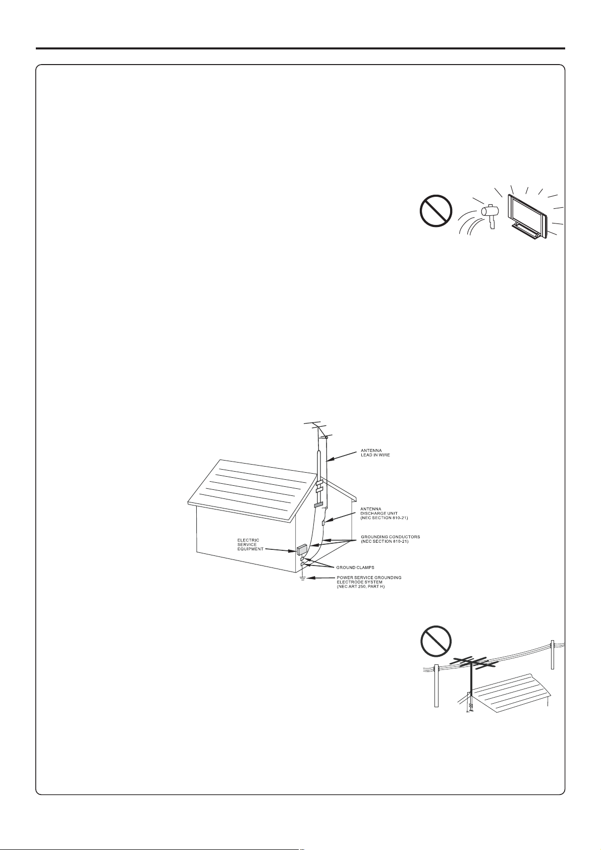
<If an outside antenna is connected to the television equipment, be sure the antenna system is
grounded so as to provide some protection against voltage surges and built-up static charges. Section
810 of the National Electrical Code provides information with respect to proper grounding of the
mast and supporting structure, grounding of the lead-in wire to an antenna discharge unit, size of
grounding conductors, location of antenna-discharge unit, connection to grounding electrodes, and
EXAMPLE OF ANTENNA GROUNDING AS PER
<An outside antenna system should not be located in the vicinity of
overhead power lines or other electric light or power circuits, or where
it can collide with such power lines or circuits. When installing an
outside antenna system, extreme care should be taken to keep from
touching such power lines or circuits, as contact with them might be
4
Page 8
Preparations
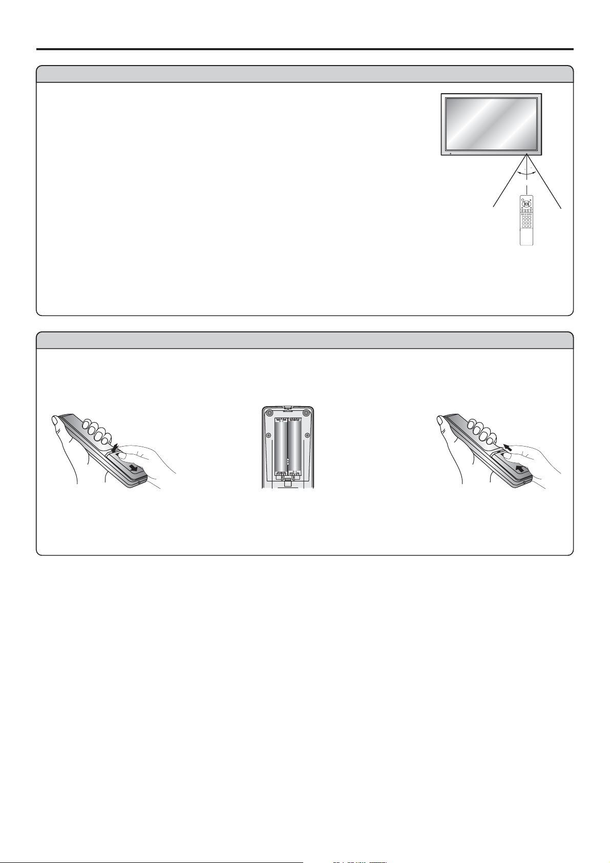
Using the Remote Control
<Use the remote control by pointing it towards the remote sensor window
of the set. Objects between the remote control and sensor window may
Note: This illustration is for reference only. The remote sensor may be in
different locations on different models.
30
30
5m
Cautions regarding use of remote control
<Do not expose the remote control to shock. In addition, do not expose the
remote control to liquids, and do not place in an area with high humidity.
<Do not install or place the remote control under direct sunlight. The heat may cause deformation of
<The remote control may not work properly if the remote sensor window of the main unit is under
direct sunlight or strong lighting. In such a case, change the angle of the lighting or PDP TV set, or
operate the remote control closer to the remote sensor window.
Batteries for the Remote Control
If the remote control fails to operate the PDP TV functions, replace the batteries in the remote control.
Open the battery
1
<(Slide the cover while
pressing down.)
Insert two size-AAA
2
<(Place the batteries with their
terminals corresponding to the
(+) and (–) indications in the
Improper use of batteries can result in a leakage of chemicals and/or explosion. Be sure to follow the
<
Place batteries with their terminals corresponding to the (+) and (–) indications.
Different types of batteries have different characteristics. Do not mix batteries of different types.
<
Do not mix old and new batteries. Mixing old and new batteries can shorten the life of new batteries
<
and/or cause old batteries to leak chemicals.
Remove batteries as soon as they are non-operable. Chemicals that leak from batteries can cause a
<
rash. If chemical leakage is found, wipe with a cloth.
The batteries supplied with the product may have a shorter life expectancy due to storage conditions.
<
If the remote control is not used for an extended period of time, remove the batteries from the remote
<
Replace the cover and
3
slide in reverse until the
5
Page 9
Preparations (continued)
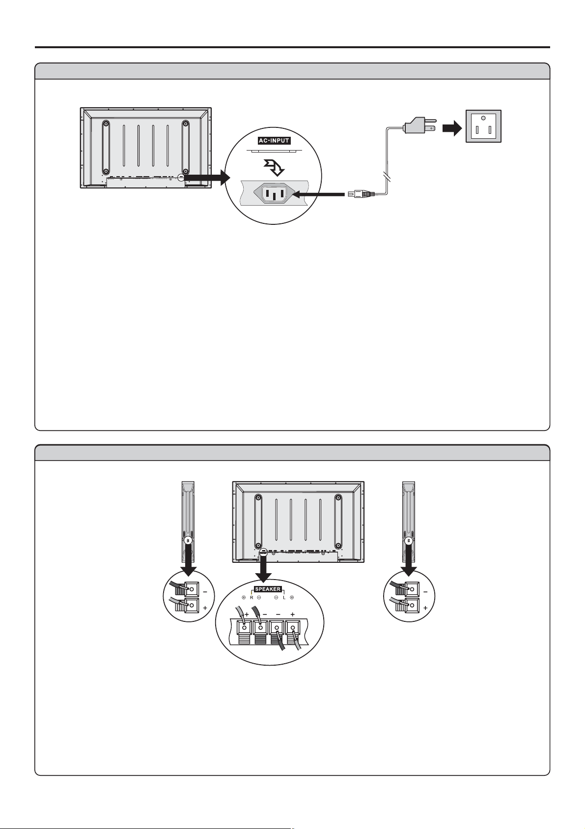
Power connection
Household
power
Plug into AC outlet.
AC cord
COMPONENTINPUT1COMPONENTINPUT1 COMPONENT INPUT2COMPONENTINPUT2
C/PrrC/PrrC/PrrC/P
C/PbbC/PbbC/PbbC/P
Y
AUDIO
AVINPUTAVINPUT
HEADPHONEHEADPHONE
AC-INPUT
SVHSSVHS
RF
Y
AUDIO
VIDEO VIDEO
RLAUDIO RLAUDIO
rr
bb
SPEAKERSPEAKER DVIDVI AVOUTPUTAVOUTPUT
CONTROLCONTROL
D-SUBD-SUB
AUDIO
L
PIC
R
PIC
AUDIO
1. Connecting the female plug to the AC socket on the unit.
2. Connecting the male plug to the wall outlet as illustrated.
Note:
<
This product should be operated only from the type of power source indicated on the marking label.
Always unplug the AC cord from power outlet when not using for a long period of time.
<
Speaker connection
COMPONENTINPUT1COMPONENTINPUT2
C/P
C/PbbC/P
Y
AUDIO
rr
ラメマ
AVINPUT
HEADPHONE
AC-INPUT
SVHS
RF
C/P
Y
AUDIO
VIDEO VIDEO
RLAUDIO RLAUDIO
rr
bb
(Black)
(Red)
Connect the speaker audio
cable to the external
speaker output jack on the
unit matching the "+" and "-"
(Black)
(Red)
SPEAKER DVI AVOUTPUT
L
R
Right
speaker
CONTROL
D-SUB
AUDIO
PIC
PIC
AUDIO
Left
speaker
ends of the cable with color.
6
Page 10
Preparations (continued)
Antenna Connection
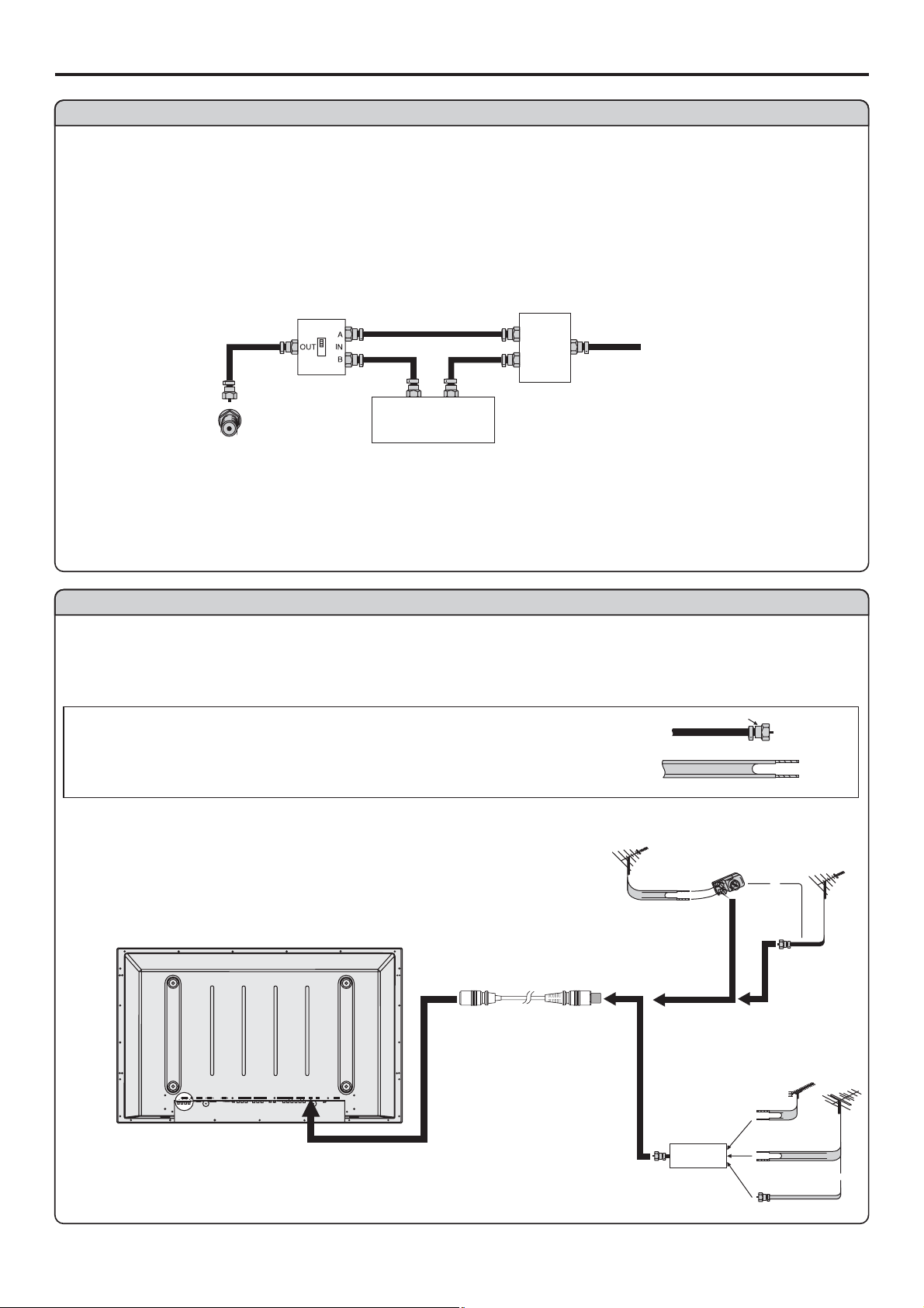
CABLE TV (CATV) CONNECTION
A 75-ohm coaxial cable connector is built into the set for easy hookup. When connecting the 75- ohm
coaxial cable to the set, screw the 75-ohm cable to the ANT. Terminal.
Some cable TV companies offer “premium pay channels”. Since the signals of these premium pay
channels are scrambled, a cable TV converter/descrambler is generally provided to the subscriber by
the cable TV company.
This converter/descrambler is necessary for normal viewing of the scrambled channels. For more
specific instructions on installing cable TV, consult your cable TV company. One possible method of
utilizing the converter/descrambler provided by your cable TV company is explained below. Please
“A” position on the RF switch (not supplied) : You can view all unscrambled channels by using the TV’s
channel keys.
“B” position on the RF switch (not supplied) : You can view the scrambled channels via the
RF switch (not supplied)
OUT
Cable TV converter/
descrambler
(not supplied)
IN
Two-set
signal
splitter
(not
supplied)
Cable TV Line
Consult your Dealer or Service Center for the type of splitter, RF switch or combiner that
Antenna connection
(Continued)
ANTENNAS
The antenna requirements for good color television reception are more important than those for black
& white television reception. For this reason, a good quality outdoor antenna is strongly recommended.
The following is a brief explanation of the type of connections that are provided with the various
1. A 75-ohm system is generally a round cable with F-type
connector that can easily be attached to a terminal without
tools (not supplied).
2. A 300-ohm system is a flat “twin-lead” cable that can be
OUTDOOR ANTENNA CONNECTION
Use one of the following two diagrams if you connect an
outdoor antenna.
A: Using a VHF/UHF combination outdoor antenna.
B: Using separate VHF and/or UHF outdoor antennas.
Connect the outdoor antenna cable lead-in to the ANT.
VHF/UHF
antenna
F-type connector
75-ohm coaxial cable (round)
300-ohm twin-lead cable (flat)
A. CombinationVHF/UHF Antenna
300-ohm
twin-lead
300/75-ohm
adapter
(not supplied)
VHF/UHF
antenna
or
75-ohm
coaxial cable
SPEAKER DVI AVOUTPUT
CONTROL
COMPONENTINPUT1COMPONENTINP UT2
D-SUB
C/P
C/P
Y
AUDIO
L
R
C/PbbC/P
AUDIO
PIC
Y
PIC
AUDIO
AUDIO
rr
rr
bb
Antenna cable
B. Separate VHFand/or
UHF Antennas
UHF
antenna
AVINPUT
HEADPHONE
VIDEO VIDEO
AC-INPUT
SVHS
RF
RLAUDIO RLAUDIO
Combiner
(not supplied)
OUT IN
300-ohm
twin-lead
300-ohm
twin-lead
75-ohm
coaxial cable
VHF
antenna
or
7
Page 11
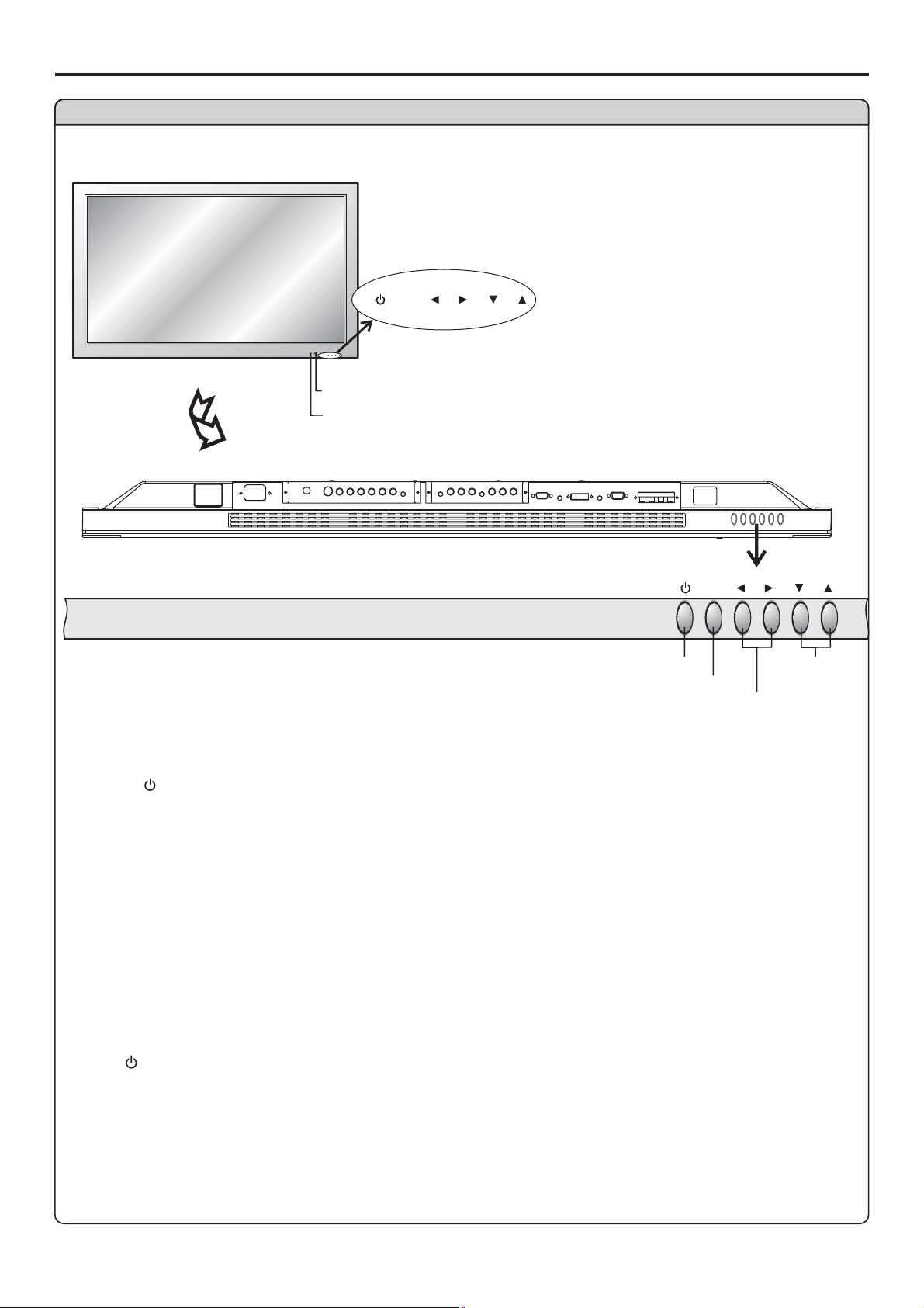
Identification of Controls
Main unit (front view)
MENU
VOL
MENU
CH
SOURCE
VOL
CH
REMOTE SENSOR
POWER INDICATOR
A blue indicator lights when the power is
on and a red indicator lights when in the
BOTTOM VIEW
POWER ON/STANDBY
MENU
VOL
MENU
VOLUME DOWN/UP
CH
CHANNEL
DOWN/UP
1. POWER
Press this button to turn the unit ON from STANDBY mode. Press it again to turn the set back to
STANDBY.
2. MENU
Press this button to access the MENU main page.
3. Volume /
Press the VOL or VOL button to directly increase or decrease the sound volume level.
34
43
In OSD Menu, press these buttons to adjust the value or setting of each item
4. Channel /
56
Press these two buttons to directly change the TV channel.
POWER VOL / CH / MENU, , and on the main unit have the same functions as the
34 56
corresponding buttons on the remote control.
This operation manual provides a description based on operating functions with the remote control.
8
Page 12
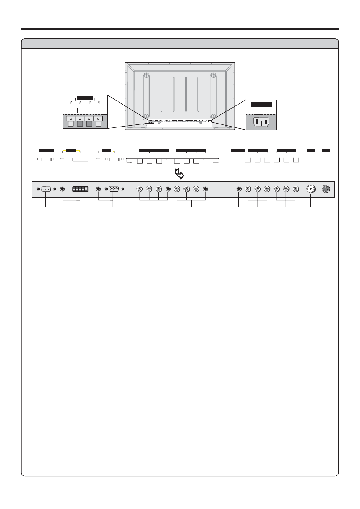
Main unit (rear view)
Identification of Controls (continued)
AC power
input socket
HEADPHONE
VIDEO VIDEO
AC-INPUT
AV INP UT
RL AUDIO RL AUDIO
CON TROL
Speaker output jacks
SPEAKER
R
DVI AVOUTPUT
AUDIO
L
DVI AVOUTPUT
CONTROL
COMPONENTINPUT1COMPONENTINP UT2
D-SUB
SPEAKER
L
R
D-SUB
D-SUB
AUDIO
PIC
PIC
COMPONENT INPUT 1COMPONENT INP UT 2
C/P
Y
bb
C/P
C/P
AUDIO
C/PbbC/P
PIC
Y
PIC
AUDIO
AUDIO
rr
Y
AUDIO
rr
AVINPUT
HEADPHONE
SVHS
RF
C/P
Y
AUDIO
VIDEO VIDEO
rr
bb
C/P
bb
AC-INPUT
RLAUDIO RLAUDIO
C/P
AUDIO
rr
BOTTOM VIEW
1
2
3
4
5
6
7
1. RS232 terminals
For service use only. The user cannot operate the unit through the RS232 terminals.
2. DVI input /Audio in
Receives the digital video/audio signals from a set top box or PC.
3. VGA input /Audio in
Connect to the VGA/audio output jacks on your PC.
4. Component inputs 1
(Y, Pb/Cb, Pr/Cr, Audio)
Connect to the audio and component output jacks of a DVD player or Set-Top Box.
Component inputs 2 (Y, Pb/Cb, Pr/Cr, Audio)
5.
Connect to the audio and component output jacks of a DVD player or Set-Top Box.
6. Headphone jack
7. AV outputs
Video, Audio L, R)
(
Connect to the VCR input jacks to record programs.
8. AV inputs
(Video, Audio L, R)
Receive video/audio signals from external sources such as VCR or DVD player.
9. Antenna input
Allows you to connect cable or outdoor antenna.
10. S-Video input
Receive a S-Video signal from external source such as VCR or DVD player.
SVHS
RF
8
10
9
9
Page 13
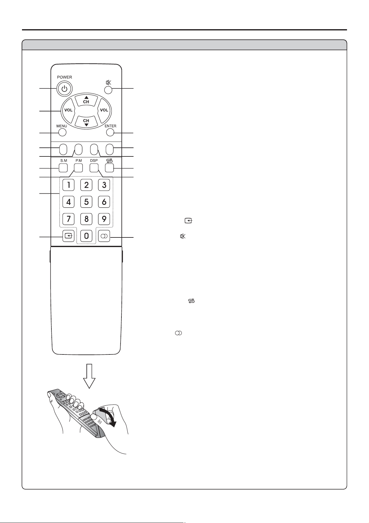
Identification of Controls (continued)
Remote Control
1. POWER
Turn the unit on or off
56
2. CH / ,VOL+/-
1
2
3
4
5
6
7
8
9
STILL
-
ZOOM
+
CLK SLP
10
11
12
13
14
15
16
56
CH / --VOL+/----Use to adjust volume;
In MENU operation, use CH to select menu item and
/-
VOL+ to adjust selected item
3. MENU
To access the MENU main page
4. STILL
To freeze current picture
5. ZOOM
To go into ZOOM or PAN mode
6. S.M
To access sound mode select menu
7. P.M
To access picture mode select menu
8. 0~9 digit buttons
Direct channel select
9. SOURCE
To access source select menu
10. MUTE
Sound mute
11. ENTER
To confirm your operation or setting or access the
submenu
12. SLP
To access Sleep timer setting menu
13. CLK
To access Current time setting menu
14. RETURN
To quickly jump between current channel and last
selected channel.
15. DSP
To display channel status or signal information
16. MTS
Use to switch channels;
56
/
10
Flip the cover, open in
the direction of the
Page 14
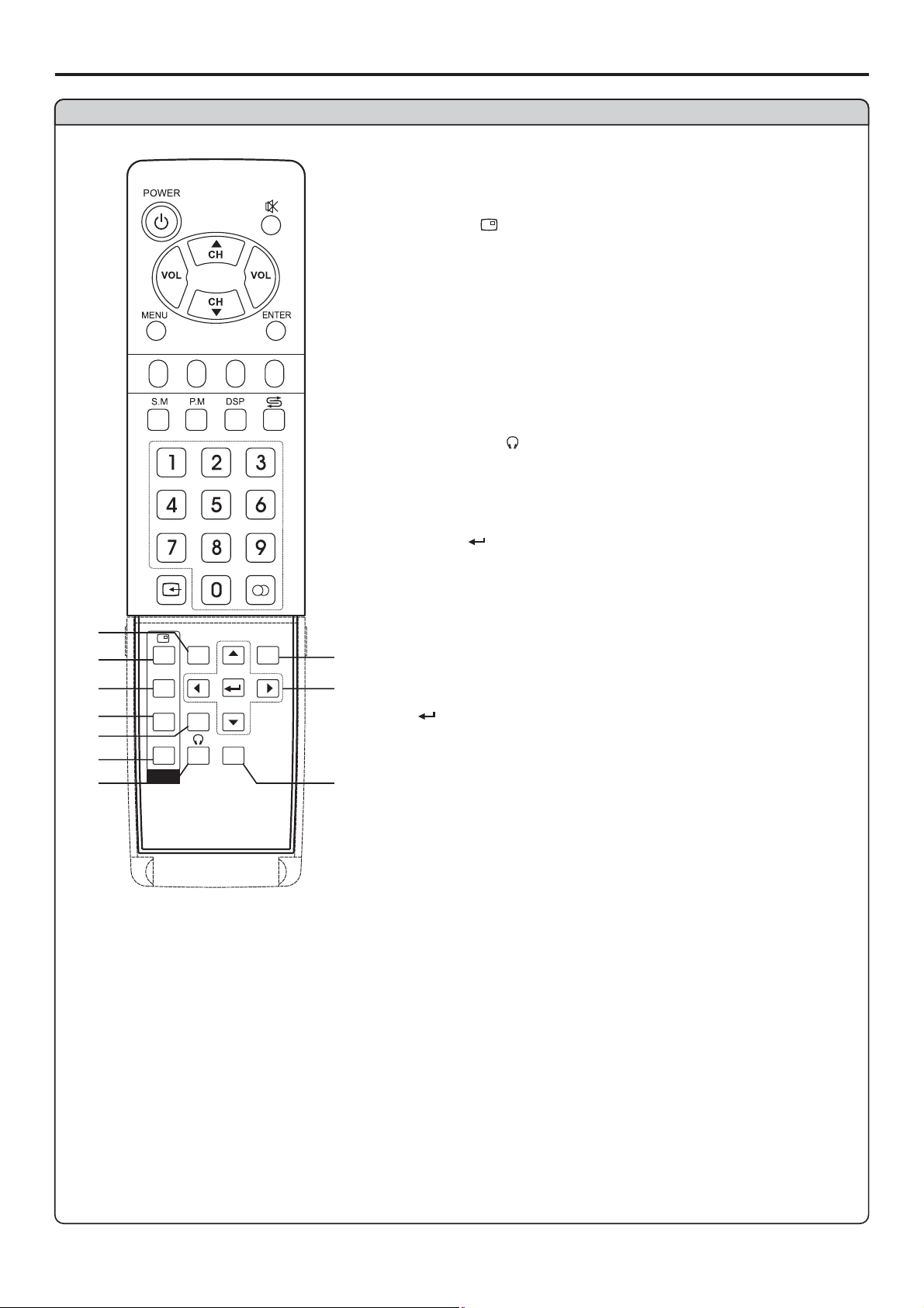
Remote Control
-
STILL
ZOOM
17
18
19
20
21
22
23
POS
SIZE
SWAP
PIP
MODE
SPEAKER
+
CLK SLP
MENU
AUTO
17. MODE
To access screen layout select menu
18. PIP display
To
19. POS
To access PIP frame position select menu
20. SIZE
To access PIP frame size adjusting menu
21. SPEAKER
In multi-picture mode, press this button t
sound of the selected picture frame from speaker
22. SWAP
The SWAP button does not work in this model.
23. HEADPHONE
In multi-picture mode, press this button to output the
sound of the selected picture frame from headphone
24. MENU
To access the MENU main page
25.
5634
56
24
34
25
26. AUTO
26
Identification of Controls (continued)
activate picture in picture
o output the
: To move upward or downward in menu operation;
To adjust zoom rate in ZOOM mode and pan
picture in PAN mode;
To select picture frame in multi-picture mode, the
selected picture frame displays with a green
border;
: To move left or right in menu operation;
To adjust selected menu item in menu operation;
To pan picture in PAN mode;
: To confirm your operation or setting or to access
a submenu.
11
Page 15
Connections
Cautions before connecting
Carefully check the terminals for position and type before making any connections.
The illustration of the external equipment may be different depending on your model.
Loose connectors can result in image or color problems. Make sure that all connectors are securely
inserted into their terminals.
Refer to the user manual of the external device as well.
When connecting an external device, turn the power off on the panel to avoid any issues.
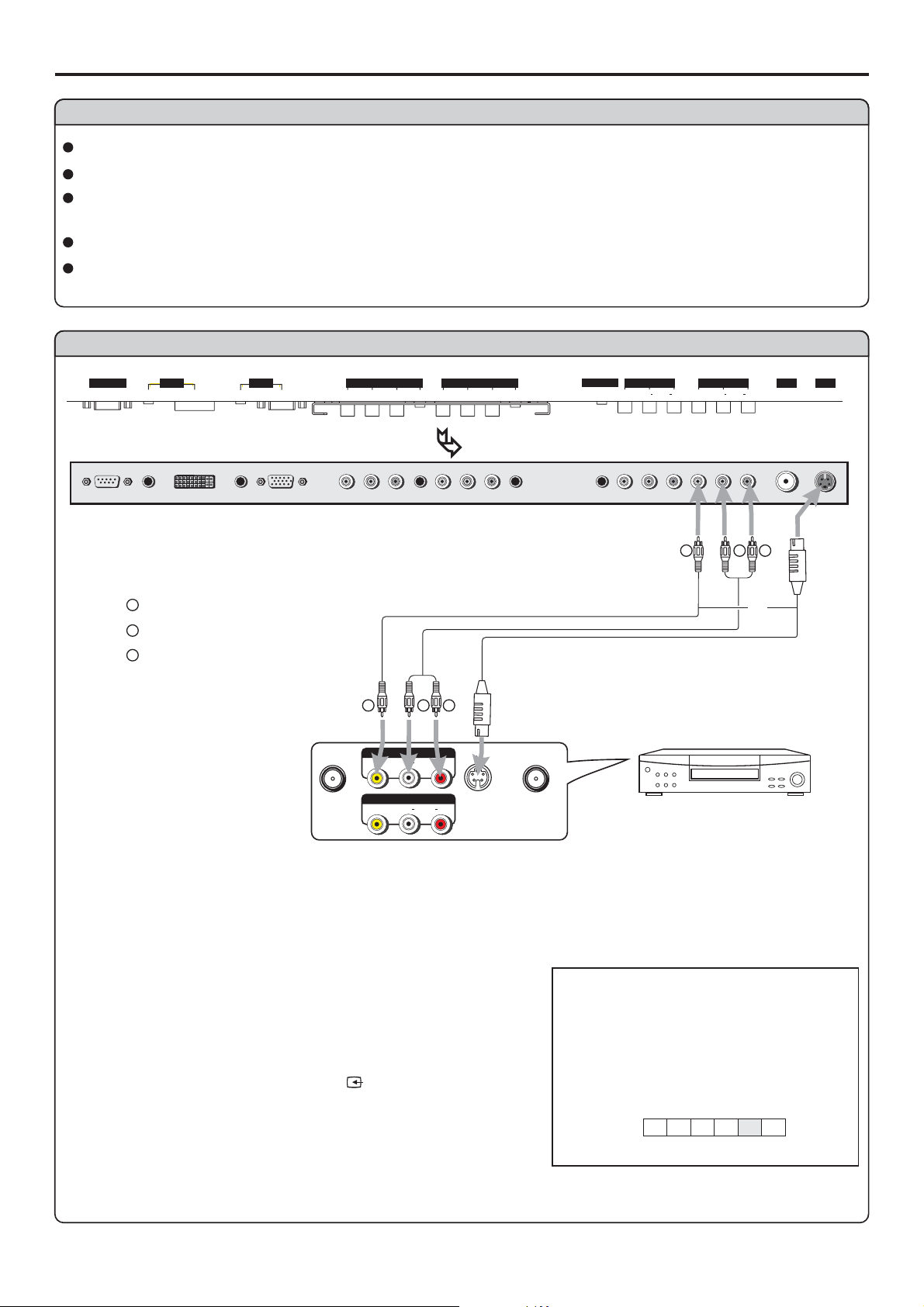
Connect a VCR
CON TROL
DVI AVOUTPUT
AUDIO
PIC
AUDIO
D-SUB
D-SUB
COMPONENT INPUT 1COMPONENT INP UT 2
C/P
PIC
C/P
Y
bb
AUDIO
rr
C/P
Y
C/P
AUDIO
rr
bb
BOTTOM VIEW
Y
Yellow (VIDEO)
W
White (AUDIO L)
RL
RL
R
S-VIDEO
S-video
cable
ANT INANT OUT
R
Red (AUDIO R )
Video
cable
Y
VIDEO
VIDEO
AVOU T
AV IN
Audio
cable
W
AUDIO
AUDIO
HEADPHONE
VIDEO VIDEO
AV INP UT
RL AUDIO RL AUDIO
Y
VCR
SVHS
RF
W
R
or
Rear of the VCR
How to connect:
Connect the / cables between the Audio (L/R)/Video jacks on the unit and VCR.Audio Video
Note:
For better video, you can use the S-video terminal if your source supports it.
When you use S-video terminal, the source menu displays instead of .SV AV
The S-Video is prior to Video terminal when they are connected at the same time.
To play VCR
1. Turn on your PDP TV , press button on the
remote control.
2. Press to select (VIDEO) and press to
VOL+/- AV ENTER
confirm.
SOURCE
source
12
A
D
C1C2
AV
TV
VIDEO
Page 16
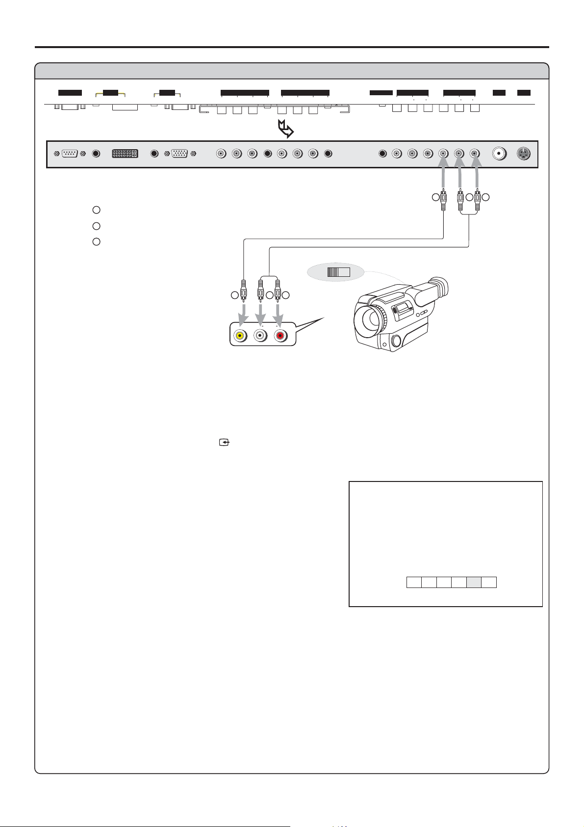
Connect a Camcorder
Connections (continued)
CON TROL
DVI AVOUTPUT
AUDIO
PIC
AUDIO
D-SUB
D-SUB
COMPONENT INPUT 1COMPONENT INP UT 2
C/P
PIC
C/P
Y
bb
AUDIO
rr
C/P
Y
C/P
AUDIO
rr
bb
HEADPHONE
BOTTOM VIEW
Y
Yellow (VIDEO)
W
White (AUDIO L)
R
Red (AUDIO R )
Video
cable
Y
Audio
cable
W
AUDIO
RLVIDEO
OUT
R
IN
VIDEO VIDEO
RL AUDIO RL AUDIO
Y
AV INP UT
SVHS
RF
W
R
How to connect:
Connect the / cables between the Audio (L/R)/Video jacks on the unit and camcorder.Audio Video
To playback Camcorder
1. Turn on your PDP TV , press button on the remote control.
2. Press to select .
VOL+/- AV (VIDEO) and press to confirmENTER
3. Turn on your camcorder and set it to output mode. (For details, refer to your camcorder user
manual.)
Note:
The operations of the camcorder may be different and is
dependant on your model. Please read the user manual of
SOURCE
source
A
D
C1C2
AV
TV
VIDEO
13
Page 17
Connections (continued)
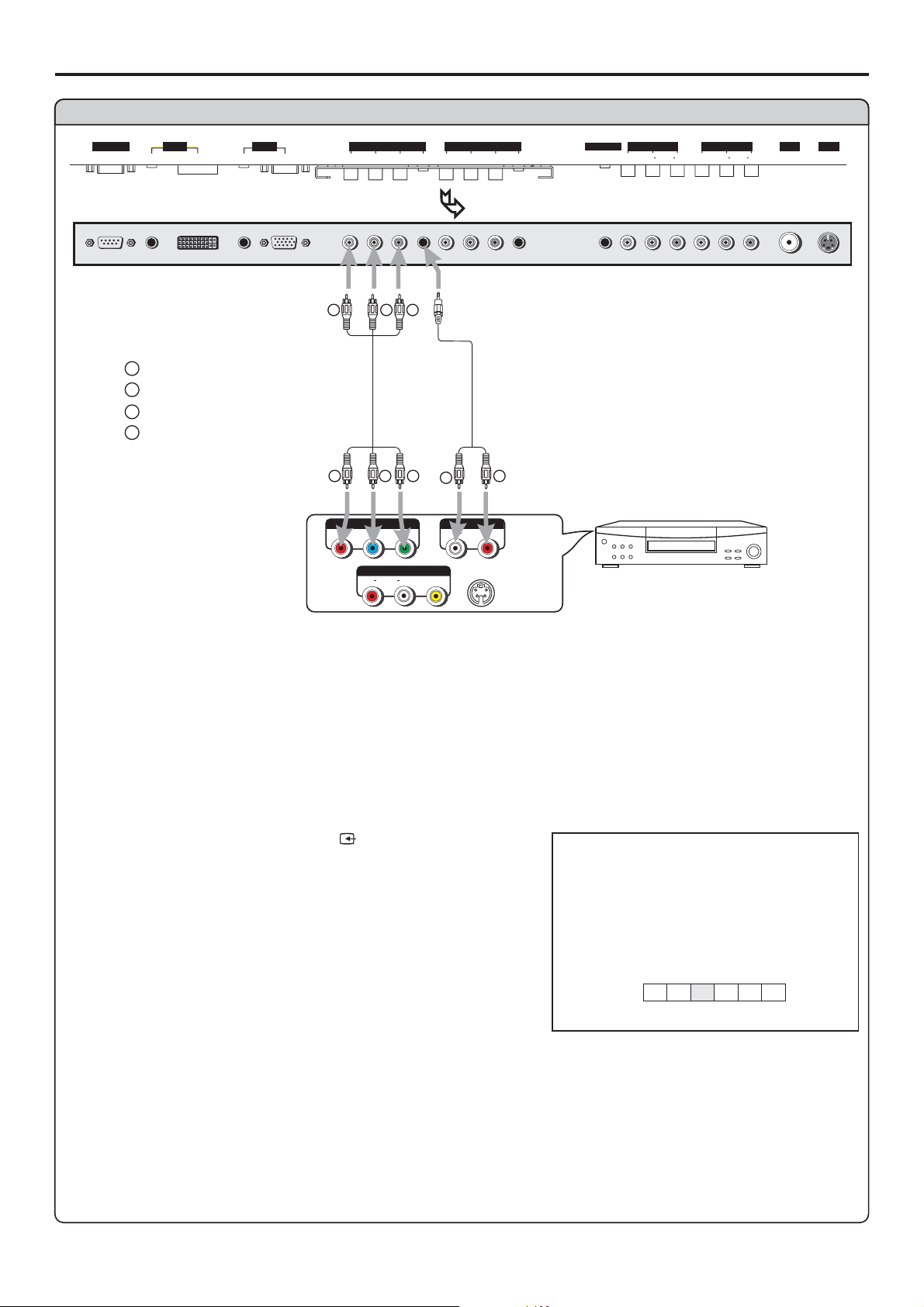
Connect a DVD player
CON TROL
DVI AVOUTPUT
AUDIO
PIC
AUDIO
D-SUB
D-SUB
COMPONENT INPUT 1COMPONENT INP UT 2
C/P
PIC
C/P
Y
bb
AUDIO
rr
C/P
Y
C/P
AUDIO
rr
bb
BOTTOM VIEW
RG B
W
white (audio L)
R
red (audio R, P /C )
Green (Y)
G
B
Blue (P /C )
r
r
Video
cable
b
b
R GB
P
P
r
Y
b
AVOU T
AUDIO
RLVIDEO
Audio
cable
W
AUDIOCOMPONENT
AUDIO
LR
S-VIDEO
R
HEADPHONE
VIDEO VIDEO
AV INP UT
RL AUDIO RL AUDIO
DVD player
SVHS
RF
Rear of the DVD player
How to connect a DVD Player using Component Video Connections:
Connect the Video cable between the Y, Cb, Cr input jacks on the unit and
DVD player.
the
Y, Cb, Cr output jacks on
To play DVD
1. Turn on your PDP TV , press button on the
remote control.
4. Turn on your DVD player, insert a DVD disc and press the
Note:
This unit identifies the type of component video terminals automatically. If you connect
the screen displays on the bottom-right corner. Similarly, if the componentterminals,
SOURCE
YCbCr detected
source
A
D
C1C2
YPbPr1/YCbCr1
AV
TV
Y, Cb, Cr
14
Page 18
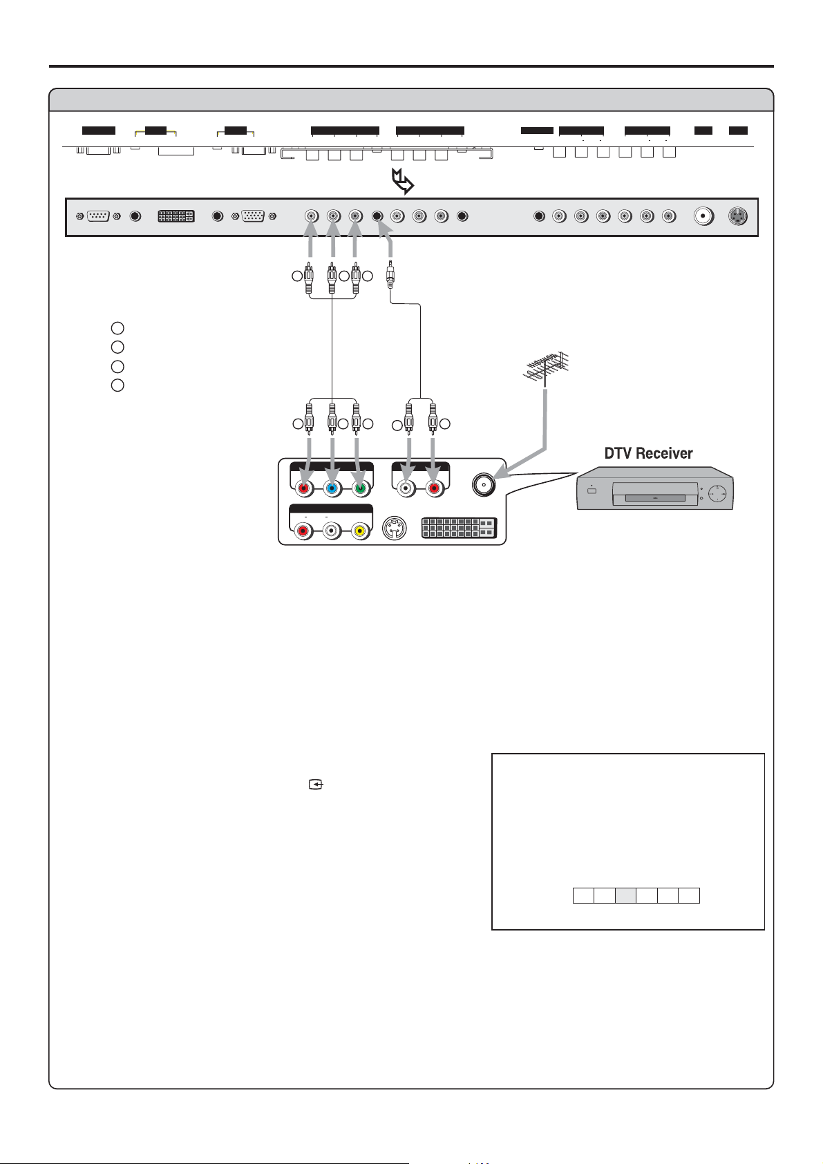
Connect a DTV receiver
Connections (continued)
CON TROL
DVI AVOUTPUT
AUDIO
PIC
AUDIO
D-SUB
D-SUB
COMPONENT INPUT 1COMPONENT INP UT 2
C/P
PIC
C/P
Y
bb
AUDIO
rr
C/P
Y
C/P
AUDIO
rr
bb
BOTTOM VIEW
RG B
W
white (audio L)
R
red (audio R, P /C )
Green (Y)
G
B
Blue (P /C )
rbr
Video
cable
b
R GB
P
P
r
AUDIO
RLVIDEO
b
AVOU T
Y
S-VIDEO
Audio
cable
W
AUDIOCOMPONENT
AUDIO
LR
R
ANT
DVI
HEADPHONE
VIDEO VIDEO
AV INP UT
RL AUDIO RL AUDIO
SVHS
RF
Rear of the DTV receiver
How to connect:
Connect the cable or antenna to the antenna input jack on the DTV receiver.
Connect the Video cable between the Y, Pb, Pr input jacks on the unit and.Y, Pb, Pr output jacks on
the DTV receiver
To Watch DTV
1. Turn on your PDP TV , press button on the
remote control.
2. Press to select (YPbPr1/YCbCr1) or
C2
VOL+/- C1
(YPbPr2/YCbCr2).
SOURCE
source
A
D
C1C2
YPbPr1/YCbCr1
AV
TV
15
Page 19
Connections (continued)
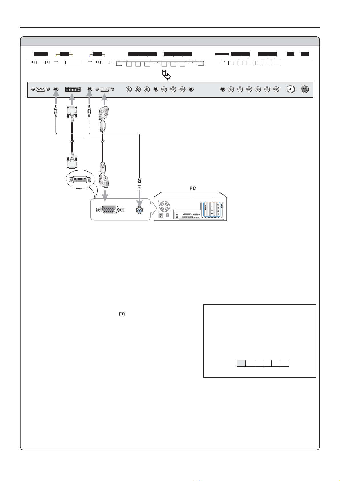
Connect a PC
CON TROL
DVI AVOUTPUT
AUDIO
PIC
AUDIO
D-SUB
D-SUB
COMPONENT INPUT 1COMPONENT INP UT 2
C/P
PIC
C/P
Y
bb
AUDIO
rr
C/P
Y
C/P
AUDIO
rr
bb
HEADPHONE
BOTTOM VIEW
or
DVI
cable
VGA
cable
Audio
cable
VIDEO VIDEO
RL AUDIO RL AUDIO
AV INP UT
SVHS
RF
How to connect:
Connect a VGA (or DVI) cable between the VGA (or DVI) jack on the PC and the VGA (or DVI) input
jack on the unit.
To Watch the PC screen
1. Turn on your PDP TV , press button on the
remote control.
2. Press to select or .
3. Press to confirm.
VOL+/- A D
ENTER
4. Turn on your PC and check for PC system requirements.
Note:
Some playback devices with DVI interface have different understandings to the HDCP protocols and
which may lead to mistakes during transferring data stream. In this case, you may find a noisy picture
while viewing programs from DVI interface. So if you encounter a noisy picture, please try to restore a
SOURCE
(VGA) (DVI)
source
A
D
C1C2
AV
TV
VGA
16
Page 20
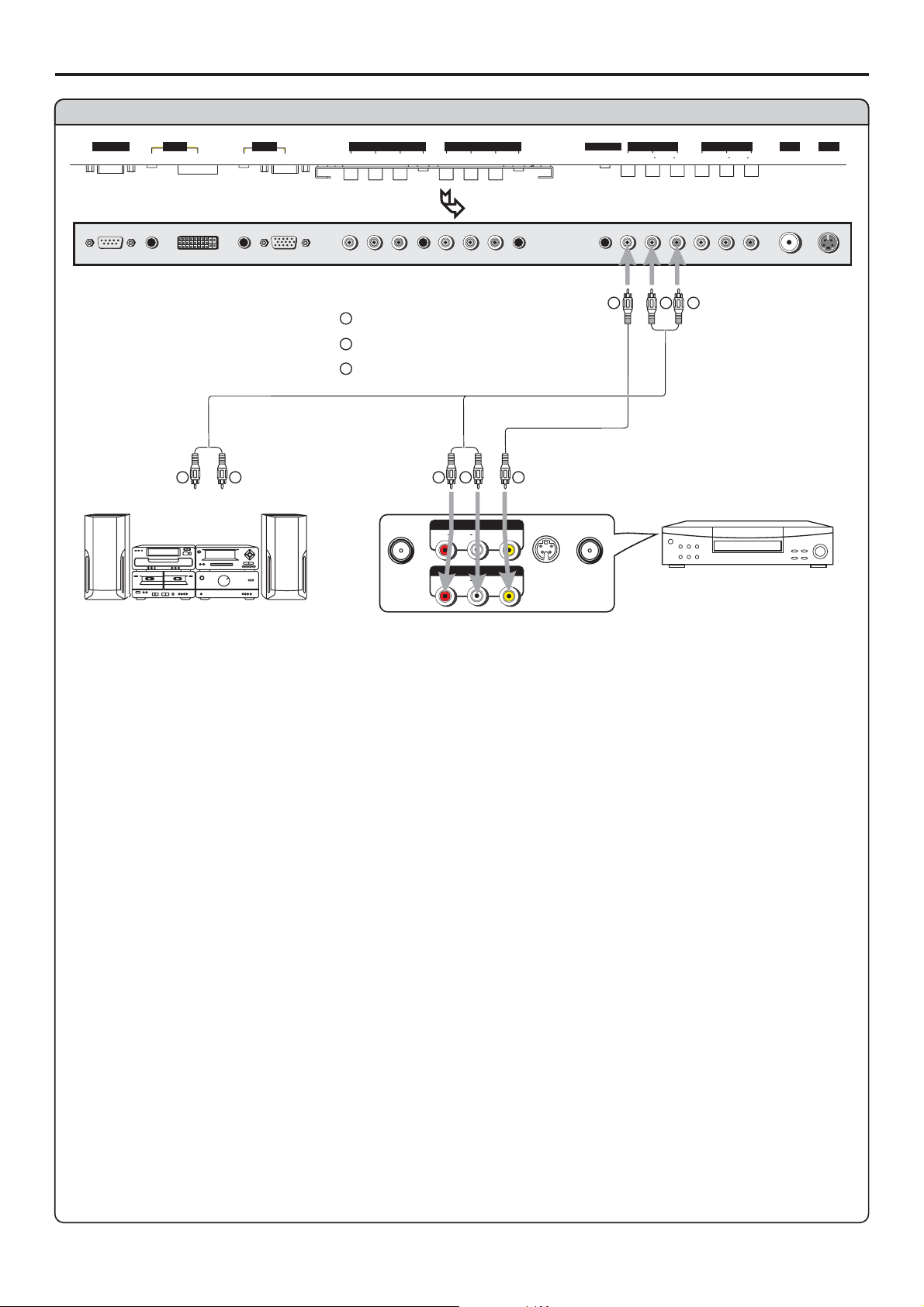
Connect a VCR (for recording) or external amplifier
Connections (continued)
CON TROL
DVI AVOUTPUT
AUDIO
PIC
AUDIO
D-SUB
D-SUB
COMPONENT INPUT 1COMPONENT INP UT 2
C/P
PIC
C/P
Y
bb
AUDIO
rr
C/P
Y
C/P
AUDIO
rr
bb
HEADPHONE
BOTTOM VIEW
Y
Yellow (VIDEO)
W
White (AUDIO L)
R
Red (AUDIO R )
Audio
cable
R
W
Audio
cable
R
Video
cable
W
Y
To Audio inputs
AVOU T
AUDIO
RLVIDEO
AV IN
AUDIO
RLVIDEO
S-VIDEO
ANT INANT OUT
VIDEO VIDEO
Y
RL AUDIO RL AUDIO
W
VCR forrecording
R
AV INP UT
SVHS
RF
External Amplifier
Rear of the VCR
How to connect:
Connect the / cables between the Audio (L/R)/Video jacks on the unit and VCR.Audio Video
- or -
Connect the Audio cables between the Audio (L/R) jacks on the unit and external amplifier.
To record program
1. Turn on your PDP TV, select a program you wish to record.
2. Turn on your VCR, insert a videotape for recording.
3. Press the Record button to begin recording.
To enjoy high-quality sound through an external amplifier
1. Turn on your PDP TV, select a program.
2. Turn the main volume of the amplifier to minimum.
3. Turn on the amplifier and adjust for a proper volume.
Note:
The operations of the amplifier may be different depending on model. Please read the user manual of
your amplifier to confirm proper operation.
The AV output terminals output audio/video signal inputted from Antenna input or AV inputs.
17
Page 21
Turning the Unit On and Off
Turning the Unit On and Off
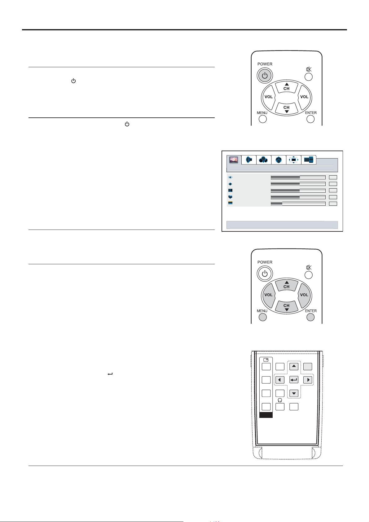
Turning On
Insert the power cord into the wall outlet.
Press the button on the remote control.
The unit will be turned on and you will be ready to use it's
Power
Turning Off
With the power on, Press the button on the remote
Power
control to turn off.
Note:
Viewing the Menus and Displays
Your PDP TV has a simple, easy-to-use menu system that
appears on the screen. This system makes it convenient and
fast to use features on the unit.
Viewing the Menus
With the power on, press the button on the remote
1
control. The main menu appears on the screen.
Use the to select menu item. Use to adjust
2
CH / VOL+/-
56
value or setting of each item. Use to confirm or
access items of menu.
On-screen menu will disappear from the screen
automatically after about 15 seconds, or you can press
the button repeatedly to exit the menu.
MENU
MENU
ENTER
-
picture
brightness
contrast
sharpness
color
tint
down for picture settings for current window
-
+
50
50
50
50
12
+
Note:
To clearly introduce the menu operations , this operation
manual provides a description based on operation with the
56
In MENU operations, the
3
function with buttons, the / buttons have
the
CH /
56
the same function with the
/ buttons have the same
34
VOL+/-
buttons, the button
POS
SIZE
SWAP
PIP
MODE
SPEAKER
MENU
AUTO
Displaying Status Information
Press the button on the remote control, the unit will display current status information such as
DSP
channel number, audio mode or signal source, etc.
18
Page 22
Memorizing the Channels
Your PDP TV can memorize and store all of the available channels for both antenna and cable channels.
After the available channels are memorized, use CH / to scan through the available stations.56
Selecting the Signal Source
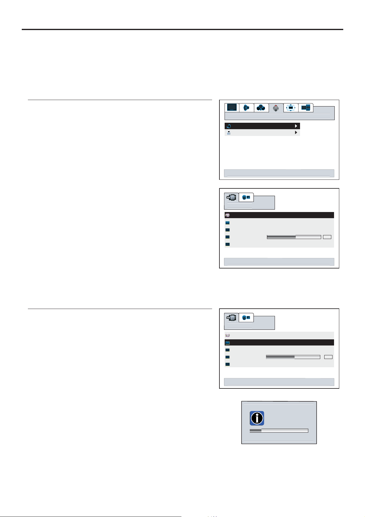
Before your PDP TV can memorize the available channels, you must specify the type of signal source
that is connected
1
2
3
4
If the menu does not display, presssearch VOL+/-
5
6
If you are connected to an antenna, please select antenna
(the selected item displays in green). If you connect cable,
please select cable.
options
tv tuner
content blocking
select to activate tuner menu
search
source antenna cable
autoset <select> to enable
auto fine tune off on
fine tune
channel skip off on
right/left to change source
50
Storing Channels in Memory Automatically
Repeat steps 1~4 in [ ] toSelecting the Signal Source
1
2
3
The unit will begin memorizing all of the available
Note:
The process of auto memory will be stopped if you press the
button.MENU
search
source antenna cable
autoset <select> to enable
auto fine tune
fine tune
channel skip
select to activate autoset
channel searching
please wait or
press menu to cancel
12
off on
off on
50
19
Page 23
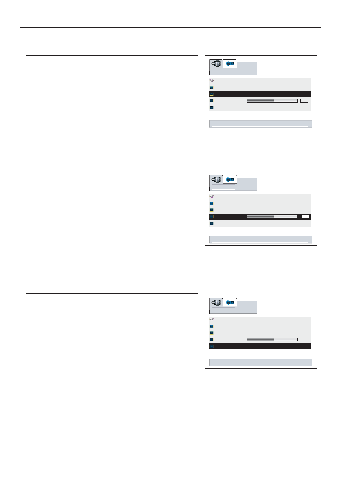
Memorizing the Channels (continued)
Setting Auto Fine Tune (AFT)
Repeat steps 1~4 in [ ] toSelecting the Signal Source
1
search
2
3
When the AFT is set to On, the unit will automatically tune
the program frequency to provide the best possible
Manual Fine Tuning
Repeat steps 1~4 in [ ] toSelecting the Signal Source
1
2
Press to fine tune till the best possible picture and
3
VOL+/-
sound are obtained.
If you fine tune a program manually, the auto fine tune
source
autoset <select> to enable
auto fine tune
fine tune
channel skip
right/left to adjust automatic fine tune
search
source
autoset <select> to enable
auto fine tune
fine tune
channel skip
right/left to adjust fine tuning
antenna cable
off on
off on
antenna cable
off on
off on
50
50
Adding and Erasing Channels
Use to directly select a channel that will
1
2
number buttons
be added or erased.
Repeat steps 1~4 in [ ] toSelecting the Signal Source
3
4
When the item is set to on, the selected channel will be
erased. off, the selected
channel will be added.
The erased channels can not be selected by using the
CH / number buttons56
When the item is set to
buttons unless you use to
search
source antenna cable
autoset <select> to enable
auto fine tune onoff
fine tune
channel skip onoff
right/left to set channel skip
50
20
Page 24

Changing Channels
Using the Channel Buttons (CH or CH )56
Basic Operations
Press the or to change channels.
When you press the
that the unit has memorized.
You will not see channels that were erased, not memorized or unavailable.
Direct Accessing Channels
Press the number buttons to go directly to a channel.
To select a one-digit channel:
Input the channel using the directly and then press or wait for 3 seconds.
To select a two-digit channel:
Input the channel using the directly and then press or wait for 3 seconds.
To select a three-digit channel:
Input the channel using the directly.
Note:
Be sure to enter the channel within 3 seconds.
When you use the number buttons, You may directly select channels that were erased.
Using the RETURN button
Press this button to switch between the current channel and the previous channel.
CH CH56
CH CH56or , the unit changes channels in sequence. You will see all the channels
0-9 number buttons ENTER
0-9 number buttons ENTER
0-9 number buttons
Adjusting the Volume
Using the volume buttons (VOL-and VOL+)
Using the Mute
Using the MUTE button
1
2
21
Page 25
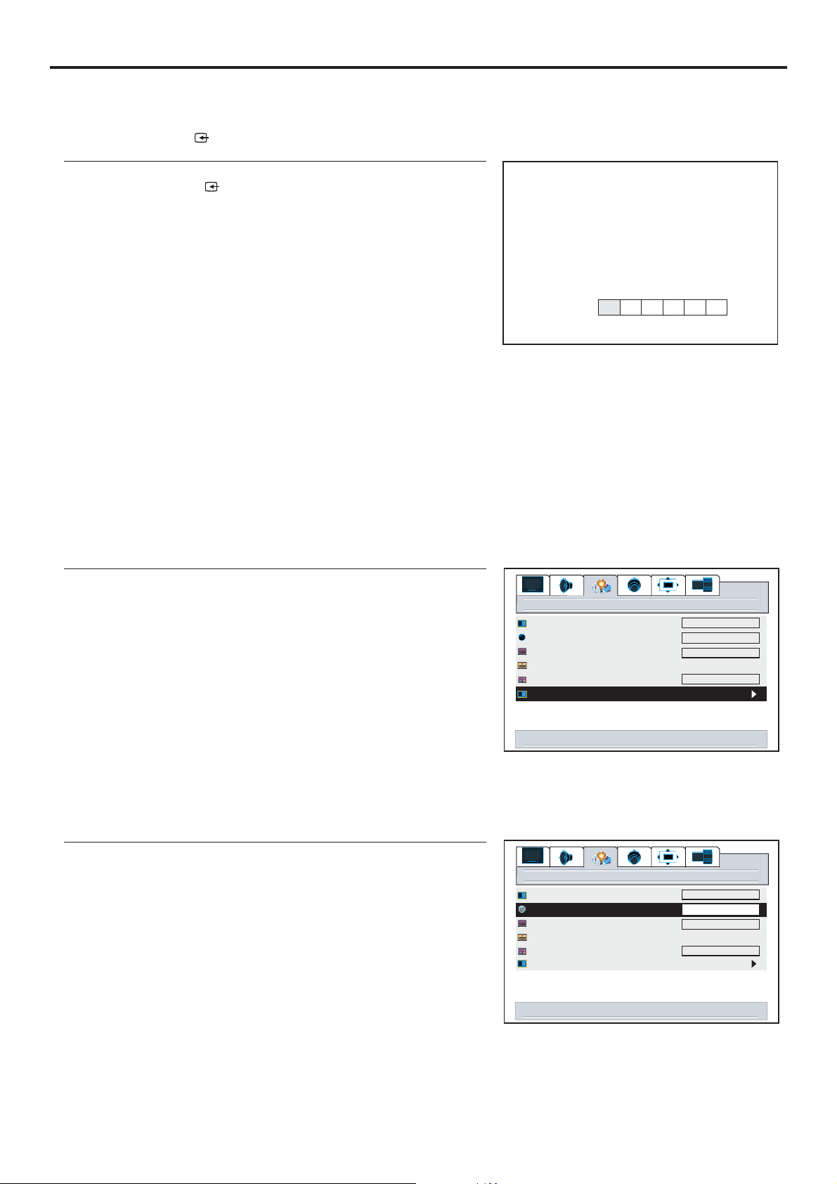
Basic Operations (continued)
Select input source signal
Using the SOURCE button
11
2
Press to confirm and the unit display signal from
3
the selected input channel.
A --------VGA, select signal from VGA (15-pin D-sub) terminals.
D--------DVI, select signal from DVI terminals.
C1 ------YPbPr1/ , select signal from YPbPr1/ terminals.
C2 ------YPbPr2/ , select signal from YPbPr2/ terminals.
AV ------VIDEO (SVIDEO), select signal from S-Video or Video terminal.
TV ------Select TV signal.
Note:
This unit identifies the type of component video terminals automatically. If you connect
Using source select menu
1
2
3
4
ENTER
source
YCbCr1 YCbCr1
YCbCr2 YCbCr2
The S-Video is prior to Video terminal when they are connected at the same time.
the screen displays on the bottom-right corner. Similary, if the componentterminals,
YCbCr detected
menu background
language
close caption mode
close caption off on on mute
close capt. background
source select
AD
settings
C1 C2
VGA
AV TV
Y, Cb, Cr
opaque
English
cc1
opaque
5
Press to confirm and the unit displays signal from
6
ENTER
the selected input channel.
Selecting a MENU language
1
2
3
Press to select the appropriate language:VOL+/-
4
5
22
right/left to source select
settings
menu background
language
close caption mode
close caption off on on mute
close capt. background
source select
right/left to change language
opaque
English
cc1
opaque
Page 26
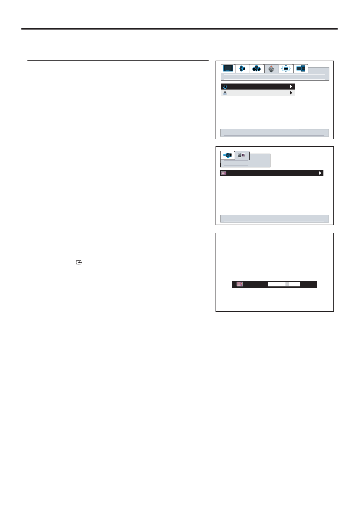
Editing Channel Label
Setting Channel Options
1
2
3
4
5
6
7
8
Use / to select character.
56
Use / to move cursor left or right.
34
Use to clear label text if you wish to reset.
SOURCE
Use to return.
MENU
options
tv tuner
content blocking
select to activate tuner menu
channel
edit labels
select to edit channel labels
ABC
channel up/down to change channels
up/down/left/right to edit label
source to clear label
menu to return
23
Page 27
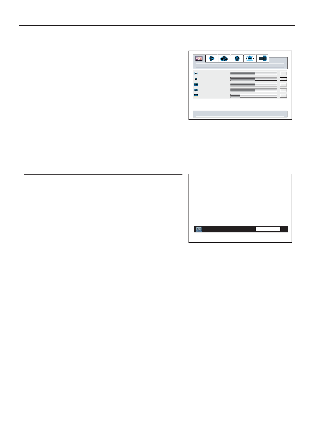
Setting Picture
Customizing the Picture
1
If the menu does not display, presspicture VOL+/-
2
3
4
Using the Preset Picture Mode
1
2
picture
brightness
contrast
sharpness
color
tint
down for picture settings for current window
50
50
50
50
12
3
There are three preset picture modes ( , and
Soft User
) and one user-set picture mode ( ).
Each preset mode has its own picture settings.
Normal
Bright
Adjusted settings are stored in User
: Select for a normal picture.
: Select for a bright picture.
Normal Bright
Picture mode
menu to return right/left to adjust
Normal
24
Page 28
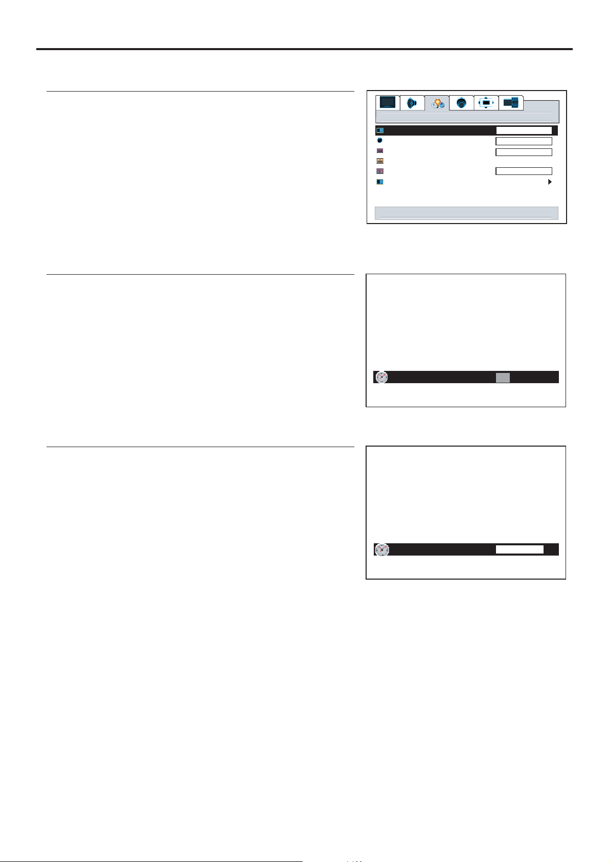
Setting the Menu Background
Setting System
1
2
3
4
Setting Current Time
1
2
3
4
settings
menu background
language
close caption mode
close caption off on on mute
close capt. background
source select
right/left to change menu background
current time
up/down to move
translucent
english
cc1
opaque
12:0 AM
right/left to adjust
Setting Sleep Timer
1
2
3
Sleep time
menu to return
off
right/left to adjust
25
Page 29
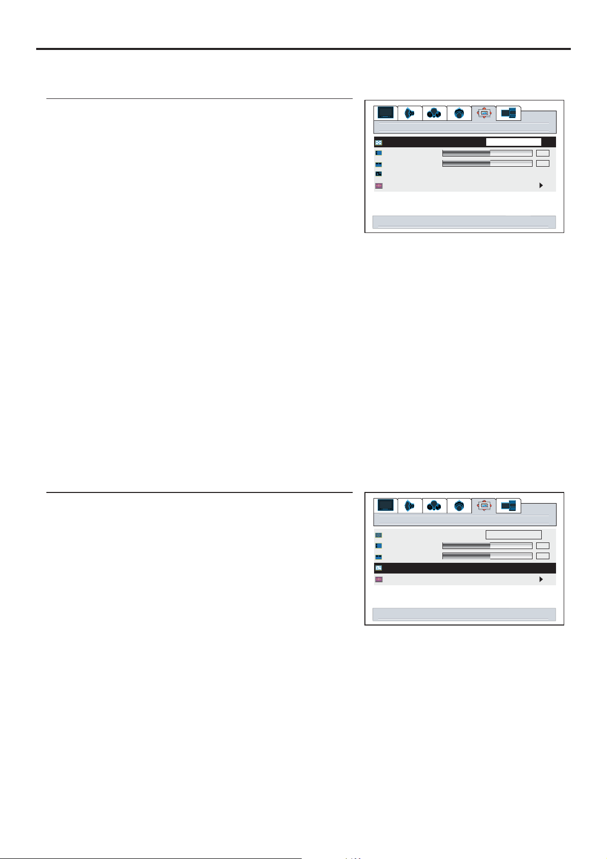
Changing Screen Options
Changing the Scaling mode of Image
1
2
3
4
The image size can be selected between: fill all, normal,
wide a zoom .nd
Fill All
The Fill All mode stretches the input vertically and horizontally to fill the display from edge to edge.
This mode is the default mode.
Normal
The Normal mode fills the display vertically with a 4:3 aspect picture, preserving the geometry of the
input format. It performs the same as the Fill to Aspect Ratio mode..
Wide
The Wide mode only affects displays that are greater than 4:3 aspect. If the picture is less than or
equal to 4:3, this mode acts as if it is in Normal mode. It is intended to display 4:3 images on a 16:9
panel with the least picture deformity. The center of the picture is left unstretched. The left and right
sides of the picture are stretched in a non-linear fashion with the areas of greatest distortion on the
extreme left and right edges of the picture. The top and bottom five percent of the picture are
cropped.
Zoom
If the display aspect ratio is greater than 4:3, this mode fills the panel horizontally, cropping 10
percent off the top and bottom of the picture. If the display aspect ratio is less than 4:3, this mode
image size
h position
v position
freeze window off on
digital pan and zoom
right/left to change image size
window
fill all
50
50
Freezing the Picture
1
2
3
4
When you set this item to , the current picture will beon
Note:
This menu item appears only when the current screen
layout is full screen.
window
image size
h position
v position
freeze window off on
digital pan and zoom
left/right to freeze current window
fill all
50
50
26
Page 30
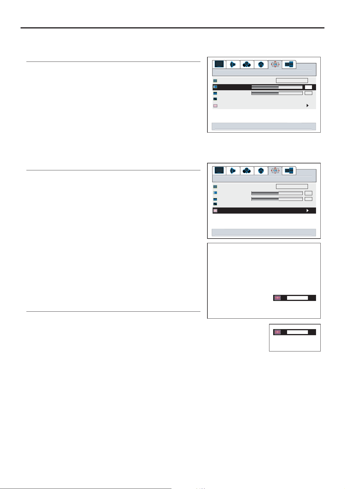
Changing Screen Options (continued)
Changing the Position of the Image
The unit allows you to adjust the position of the image if it is not well-aligned.
1
2
3
4
Using Digital Pan and Zoom
1
2
3
4
window
image size
h position
v position
freeze window off on
digital pan and zoom
right/left to adjust h position
window
image size
h position
v position
freeze window off on
digital pan and zoom
select to activate digital zoom control
fill all
50
50
fill all
50
50
5
Note:
You can quickly access Zoom menu by using the
button.
The unit allows you to pan the picture after you zoom in the
Repeat steps 1~5 above to zoom in the picture.
1
ZOOM
2
Press VOL+/- CHor / to pan the current picture in the
3
relevant direction.
56
1.00
up/down to zoom
<select> for pan
menu to exit
12.34
arrow keys to pan
<select> for zoom
menu to exit
27
Page 31
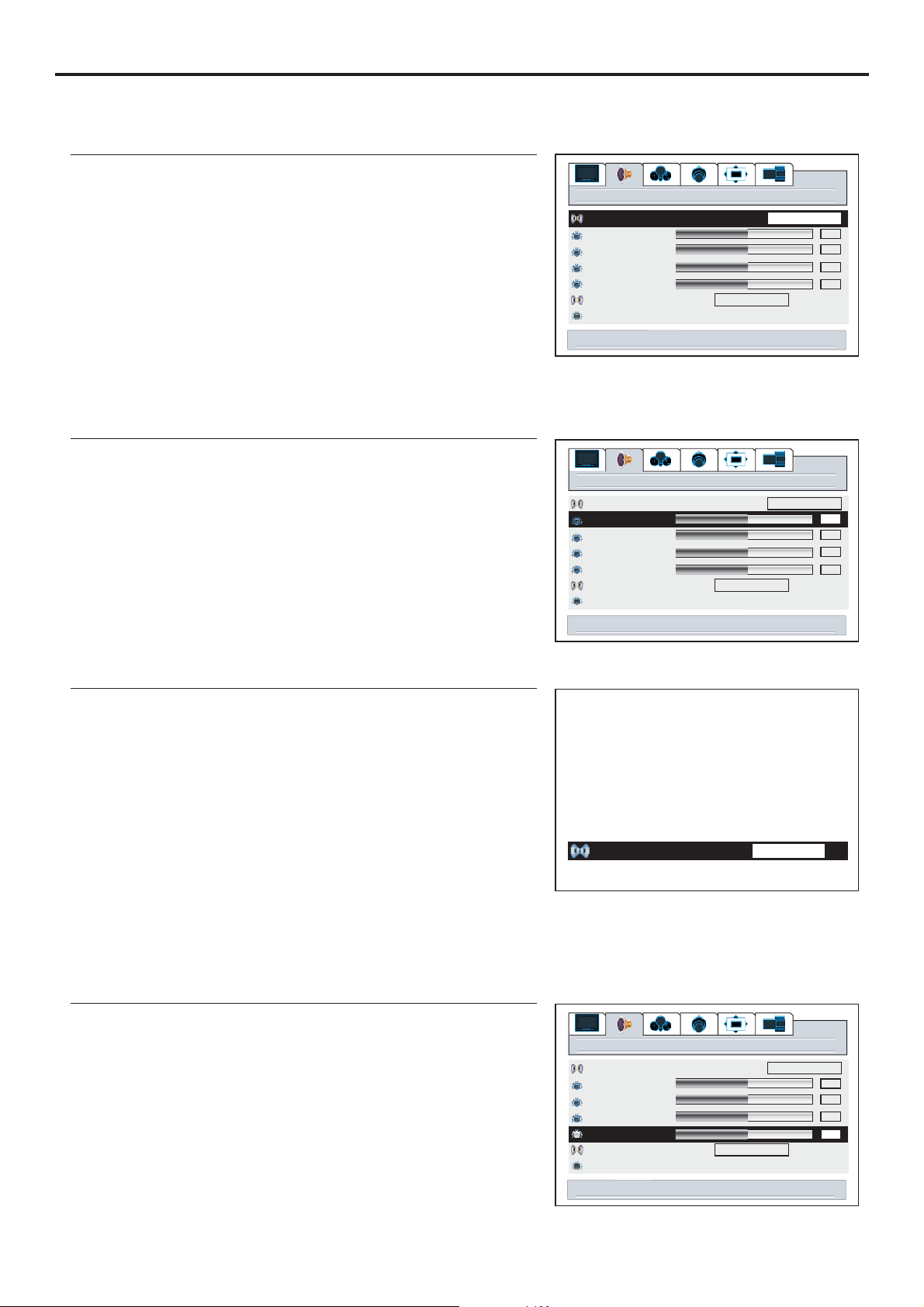
Setting Sound
Using the Preset Audio Mode
1
2
3
4
Note:
You can not access the and item unless thetreble bass Audio
Customizing the Sound
1
2
3
4
audio
Audio mode
treble
bass
balance
headphone
MTS
auto volume off on
right/left to set audio mode
Audio mode
treble
bass
balance
headphone
MTS
auto volume off on
right/left to adjust treble
STEREO
audio
STEREO
Cinema
50
50
50
50
User
50
50
50
50
Using the S.M button
1
2
3
There are three preset Audio modes ( , and
News User
) and one user-set Audio mode ( ).
Each preset mode has its own Audio settings.
Cinema
Music
News
Adjusted settings are stored in User mode.
: Select for a movie program picture.
: Select for a music program.
: Select for a speech or conversation program.
Adjusting the Headphone Volume
Cinema Music
1
2
3
4
Audio mode
menu to return
Audio mode
treble
bass
balance
headphone
MTS
auto volume off on
right/left to adjust headphone
right/left to adjust
audio
Cinema
Cinema
50
50
50
50
STEREO
28
Page 32
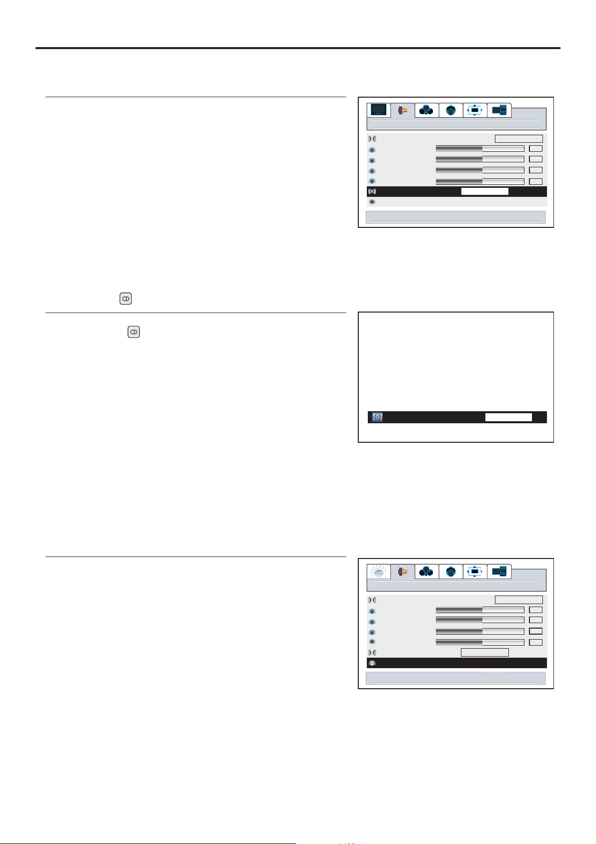
Choosing a Multi-Channel Sound ( ) SoundtrackMTS
Setting Sound (continued)
1
audio
Cinema
2
3
Audio mode
treble
bass
balance
headphone
MTS
auto volume off on
right/left to set stereo
STEREO
4
Choose for channels that are broadcasting in stereo.
Choose for channels that are broadcasting in mono, or if you are having difficulty receiving
a stereo signal.
Using the MTS button
STEREO
MONO
1
2
50
50
50
50
3
MTS
menu to return right/left to adj stu
Using the Auto Volume
Each broadcasting station has its own signal conditions, which can make it necessary to adjust the
volume every time the channel is changed. “Auto volume” lets you automatically adjust the volume of
the desired channel by lowering the sound output when the modulation signal is high or by raising the
STEREO
1
audio
Cinema
50
50
50
50
2
3
4
Audio mode
treble
bass
balance
headphone
MTS
auto volume onoff
right/left to set auto volume
STEREO
29
Page 33
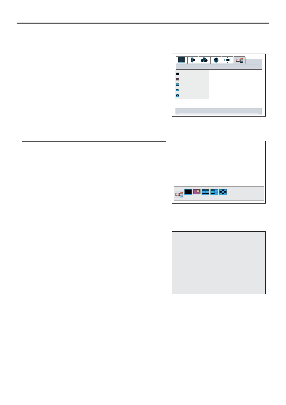
Changing Screen Layout
Selecting Screen Layout
Using the Layout Menu
1
2
3
4
Using the MODE button
1
2
3
4
layout
full screen
pip
split screen
pop3
grid
down for current screen layout options
pip
select to change layout
menu to exit
Full Screen
When this item is selected, only main frame displays on the
Main Frame
30
Page 34
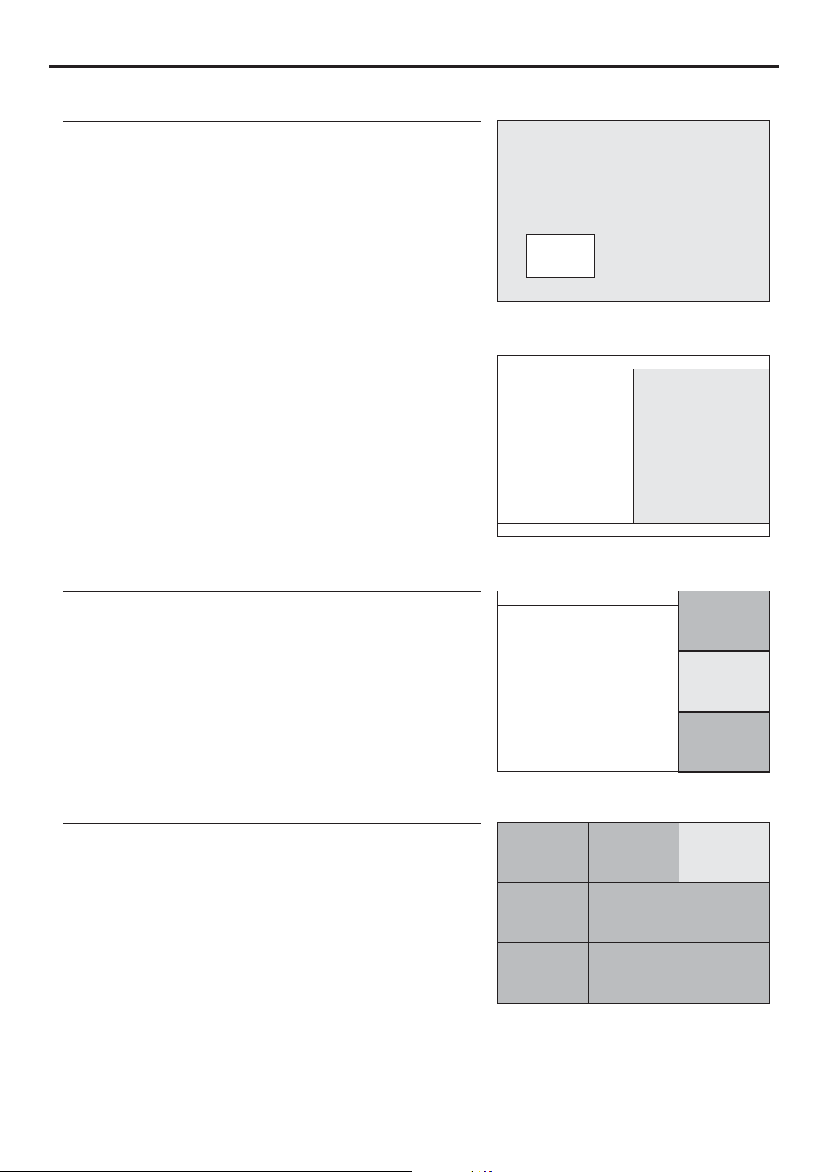
Changing Screen Layout (continued)
PIP
When this item is selected, one main frame and one PIP frame
display on
Split Screen
When this item is selected, the screen will be split into two
Main Frame
PIP Frame
Main Frame Split Frame
POP3
When this item is selected, one main frame and three
scanning frames display on the screen.
Grid
When this item is selected, the screen displays 9 scanning
Main Frame
1
4
7
2
5
8
Scanning
Frame
Scanning
Frame
2
3
4
3
6
9
31
Page 35
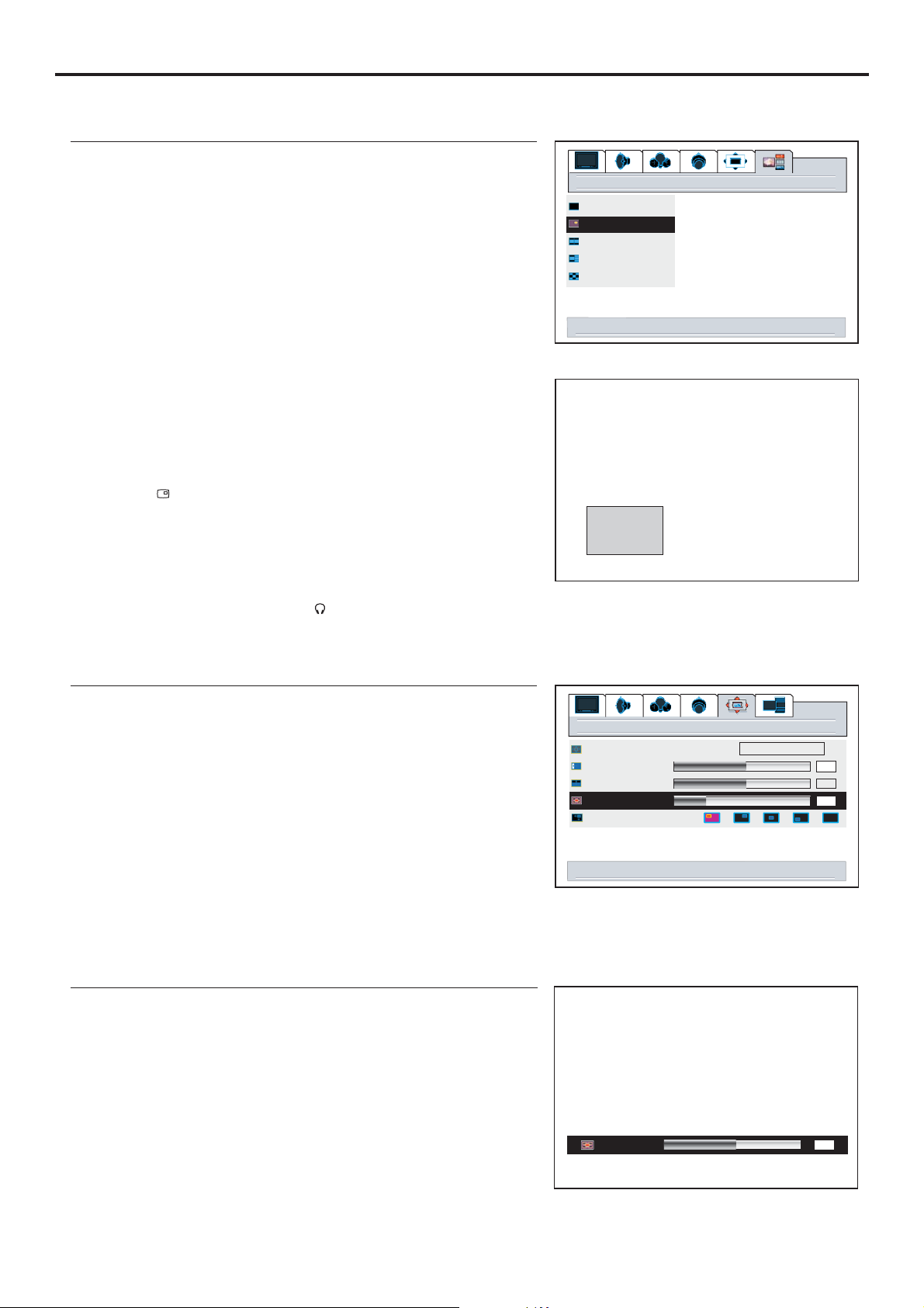
PIP Operations
Viewing the Picture-in-Picture
1
2
3
4
The screen displays one main frame and one PIP frame.
Press or to select main frame or PIP frame.56
5
The selected frame displays with a green border.
Note:
4
You can quickly open or close PIP frame by directly using
PIP displaying
the button.
4
Many but not all adjustments and settings can be applied
to the PIP picture when the PIP frame is selected.
4
To cancel PIP frame, press the button or
select the full screen item and confirm.
4
The audio of the selected picture can be output from the
speaker or headphone by using the or button
PIP displaying
SPEAKER
layout
full screen
pip
split screen
pop3
grid
select activates pip window layout
Main Frame
PIP Frame
Adjusting the Size of PIP Frame
With the PIP frame displaying, press to display the
1
menu main page.
MENU
2
3
4
5
Using the buttonSIZE
1
2
3
image size
h position
v position
pip size
pip position
right/left to adjust PIP size
window
fill all
50
50
12
32
pip size
menu to return right/left to adjust
50
Page 36
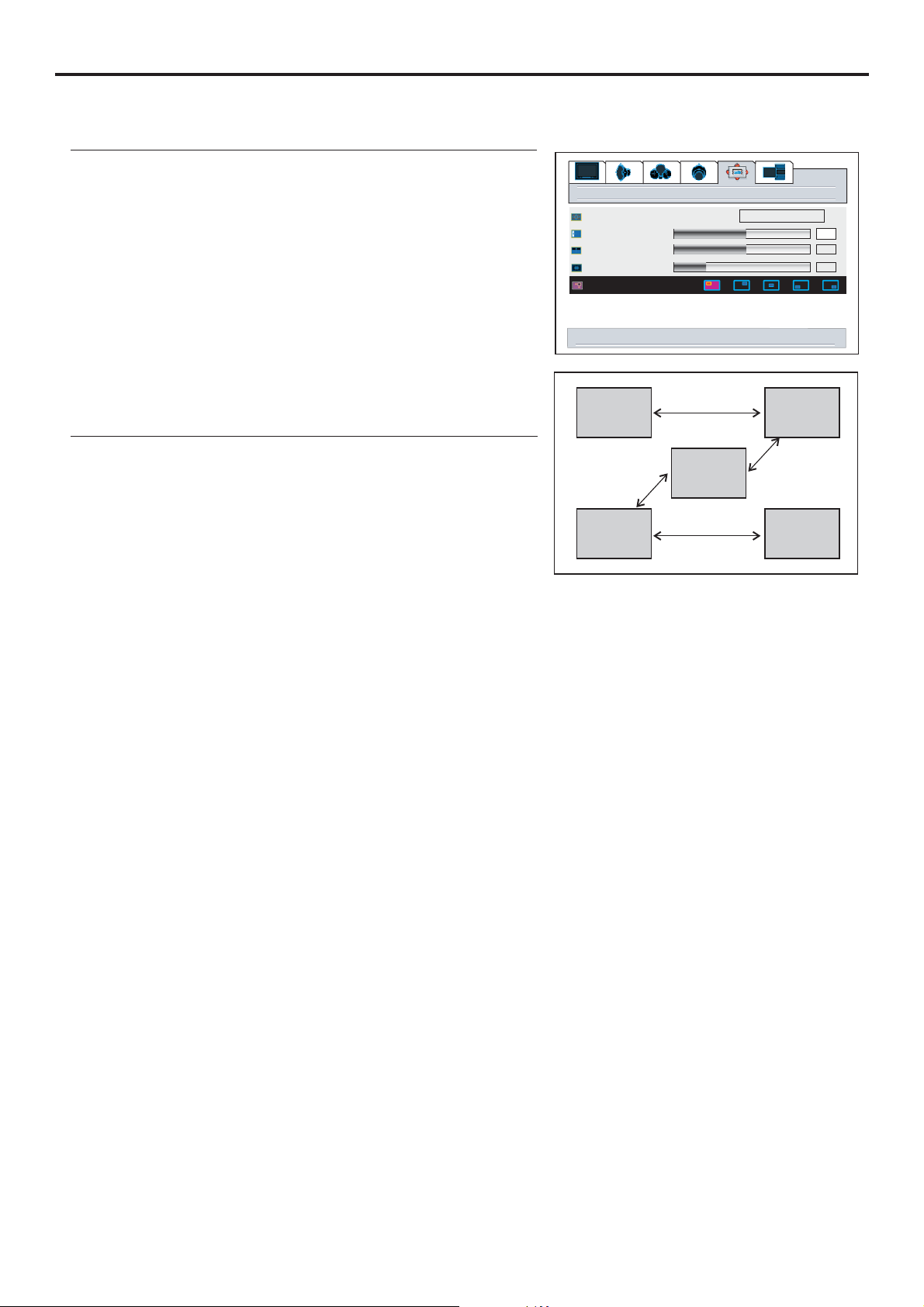
Changing the Position of the PIP Frame
PIP Operations (continued)
With the PIP frame displaying, press to display the
1
menu main page.
MENU
2
3
4
Using the buttonPOS
Press the button to quickly access the
1
select menu.
POS pip position
2
3
image size
h position
v position
pip size
pip position
right/left to adjust PIP position
PIP frame
window
fill all
50
50
12
Main frame
33
Page 37
Adjustment in PC (VGA) Mode
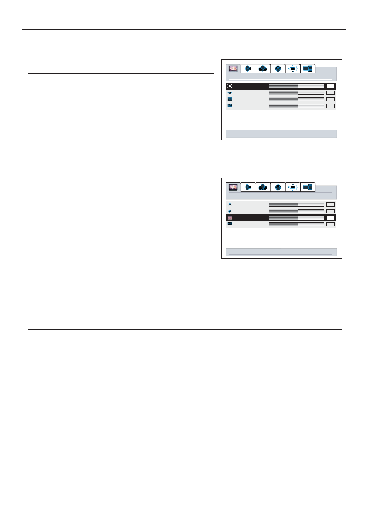
With working in VGA mode, this unit allows you to perform several adjustments.
Adjusting Picture
1
If the menu does not display, presspicture VOL+/-
brightness
contrast
phase
frequency
2
picture
50
50
50
50
3
right/left to adjust brightness
Adjusting the Phase and Frequency
1
If the menu does not display, presspicture VOL+/-
2
brightness
contrast
phase
frequency
picture
3
4
You may find that images blur, depending on the clock phase of your PC's Processor. If you
experience blurring ,
you can obtain a clearer image by adjusting the phase setting.
Adjust the clock frequency of the set's internal clock signal. If shimmering or rainbow-like
right/left to adjust phase
50
50
50
50
Adjusting the Picture Automatically
If you are not satisfied with the picture , you may quickly adjust the picture by using the button.AUTO
After the button is pressed, the message " appears on the screen and the picture
adjustments are automatically activated.
34
AUTO Auto running”
Page 38
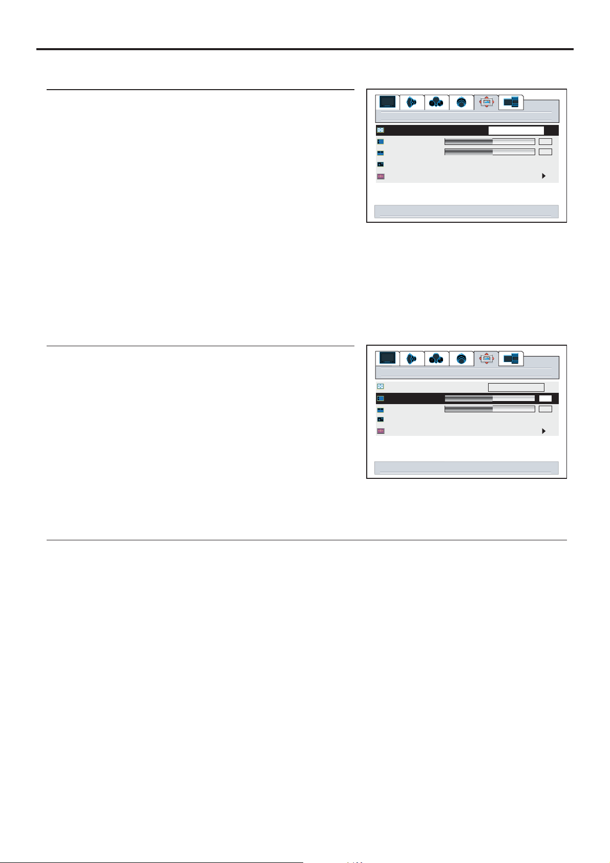
Adjustment in PC (VGA) Mode (continued)
Changing the Scaling mode of Image
1
2
3
4
image size
h position
v position
freeze window off on
digital pan and zoom
right/left to change image size
window
5
Changing the Position of Image
After connecting the unit to your PC, adjust the position of the screen if it is not well-aligned.
1
2
3
Press to adjust the value of the item until the
4
screen is well-aligned.
VOL+/-
image size
h position
v position
freeze window off on
digital pan and zoom
window
right/left to adjust h position
5
fill all
50
50
fill all
50
50
Displaying the Information
When the button is pressed in PC (VGA) mode, the unit displays some information such as the
vertical frequency and resolution.
DSP
35
Page 39
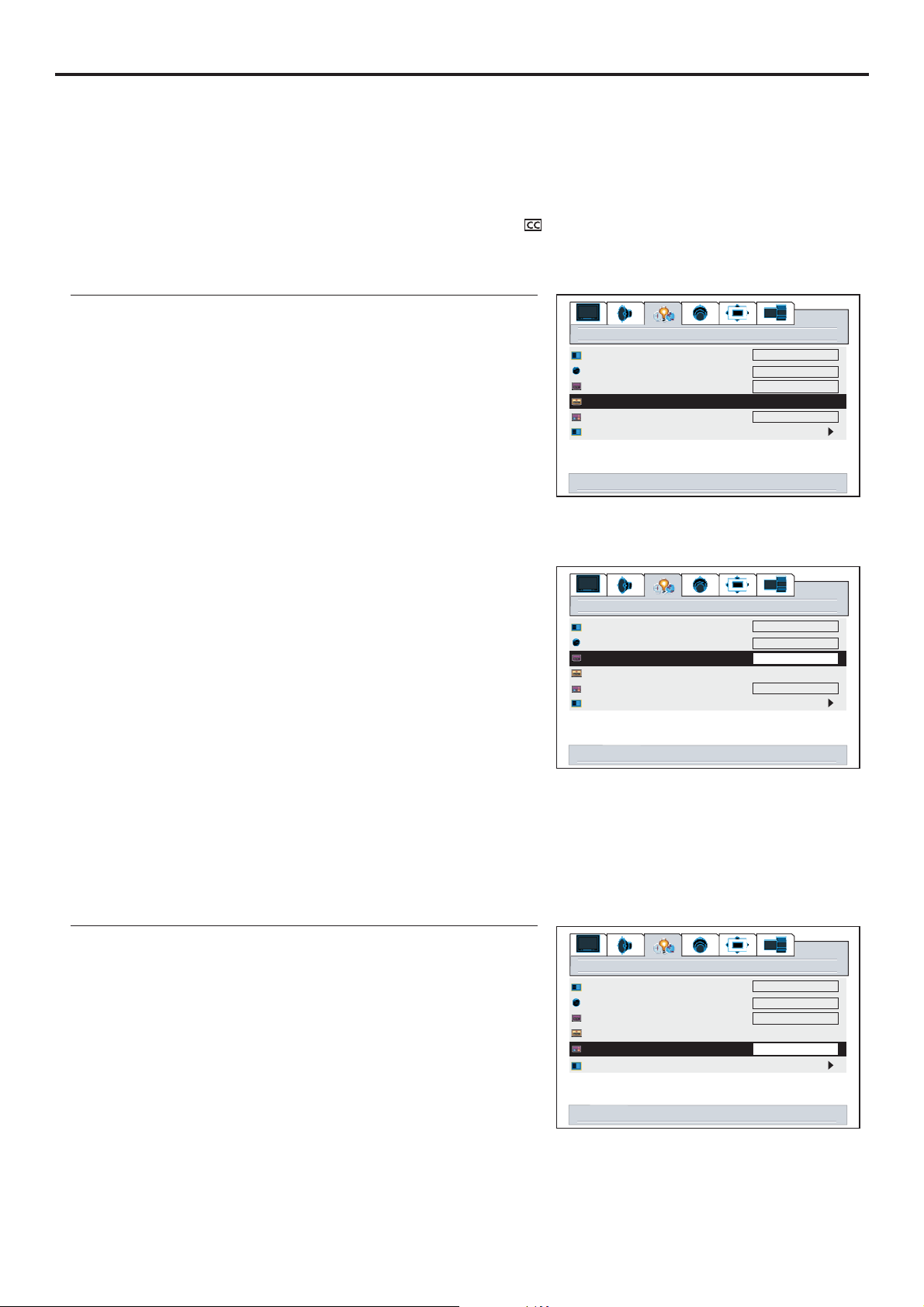
Viewing Closed Captions
The unit decodes and displays the closed captions that are broadcast with certain TV shows. These
captions are usually subtitles for the hearing impaired or foreign language translations. All VCRs record
the closed caption signal from television programs, so home-recorded video tapes can also provide closed
captions. Most prerecorded commercial video tapes provide closed captions as well. Check for the closed
Note:
The Caption feature works in TV mode only.
Not all the programs and videos will offer closed captioning. Please look for the symbol to ensure that
Setting Closed Caption
1
menu background
2
3
4
---Turn off the closed caption. If you select the
Off off,
close caption mode close capt. background
can not be accessed.
---Turn on the closed caption.
On
On Mute
---Turn on the closed caption when mute. If you
select the andon mute, close caption mode
and
5
6
The Closed Caption broadcasts can be viewed in two
modes: CAPTION and TEXT. For each mode, four
The [CAPTION] mode shows subscripts of dialogues and commentaries of TV dramas and news
programs while allowing a clear view of the picture.
The [TEXT] mode displays various information over the picture (such as TV program schedule,
weather forecast, etc.) that is independent of the TV programs.
language
close caption mode
close caption off on on mute
close capt. background
source select
right/left to control close caption
menu background
language
close caption mode
close caption off on on mute
close capt. background
source select
right/left to select close caption mode
settings
opaque
English
cc1
opaque
settings
opaque
English
cc1
opaque
Setting the Background of Closed Caption
1
2
3
4
36
settings
menu background
language
close caption mode
close caption off on on mute
close capt. background
source select
right/left to select close caption background
opaque
English
cc1
opaque
Page 40
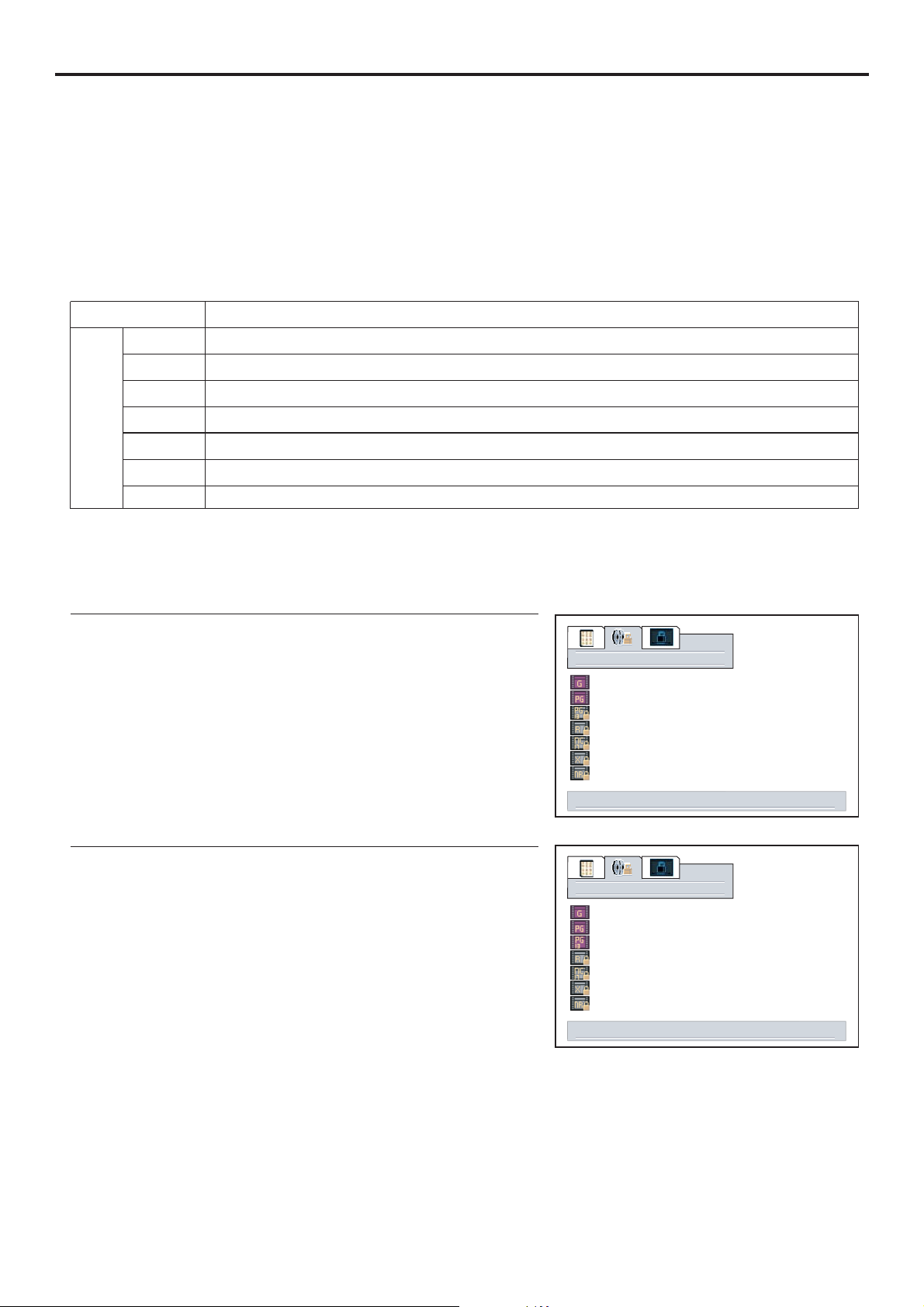
Adjusting Parental Control Settings
Parental Control
This function allows TV programs to be restricted and TV usage to be controlled based on FCC data. It
prevents children from watching violent or sexual scenes that may be harmful.
Restriction of TV programs includes two ratings that contain information about the program: the MPAA
rating and the TV Parental Guidelines. The MPAA rating is restricted by age. TV Parental Guidelines are
restricted by age and content.
[1] Movie Rating (MPAA)
Rating
age
based
G
PG
PG-13
R
NC-17
X
NR
GENERAL AUDIENCES. All ages admitted.
PARENTAL GUIDANCE SUGGESTED. Some material may not be suitable for children.
PARENTAL STRONGLY CAUTIONED. Some material may be inappropriate for children
under 13.
RESTRICTED. Under 17 requires accompanying parent or adult guardian.
NO ONE 17 AND UNDER ADMITTED.
X Rating is an older rating that is unified with NC-17 but may be encoded in the data of
Note:
The Movie rating is only age-
Example 1:
“PG-13” in the age based rating is blocked, this will
automatically block the higher ratings “R”, “NC-17”, “X” also.
Example 2:
“R” in the age based rating is blocked, this will automatically
block
Movie blocking
select to adjust movie blocking level, menu to return
Movie blocking
select to adjust movie blocking level, menu to return
37
Page 41
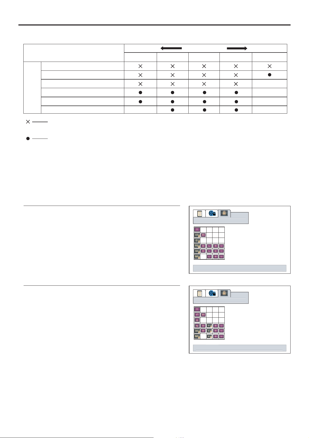
Adjusting Parental Control Settings (continued)
[2] TV Parental Guidelines
Rating
content based
FVV
age
based
TV-Y (All children)
TV-Y7 (Direct to Older Children)
TV-G (General Audience)
TV-PG (Parental Guidance
Suggested)
TV-14 (Parents Strongly
Content Rating can be set but this Rating
is not normally broadcast by TV Station.
Content Rating can be set.
LD
D:
Sexually Suggestive Dialog
L:
Adult Language
S:
Sexual Situation
V:
Violence
FV:
Fantasy Violence
S
Note:
Age-based ratings can be modified by the content-based ratings but only in the combinations indicated
by an in the table above.=
Example 1:
When TV-Y7 in the age-based rating is set to BLOCK, this will
automatically block the higher ratings: TV-G, TV-PG, TV-14
Example 2:
When TV-14 in the age-based rating is set to BLOCK, this will
automatically block the higher ratings: TV-MA.
In addition, if you block “L” sub-rating in TV-PG, then the “L”
sub-ratings in TV-14 and TV-MA will automatically be
tv blocking
select to adjust tv blocking level, menu to return
tv blocking
select to adjust tv blocking level, menu to return
38
Page 42
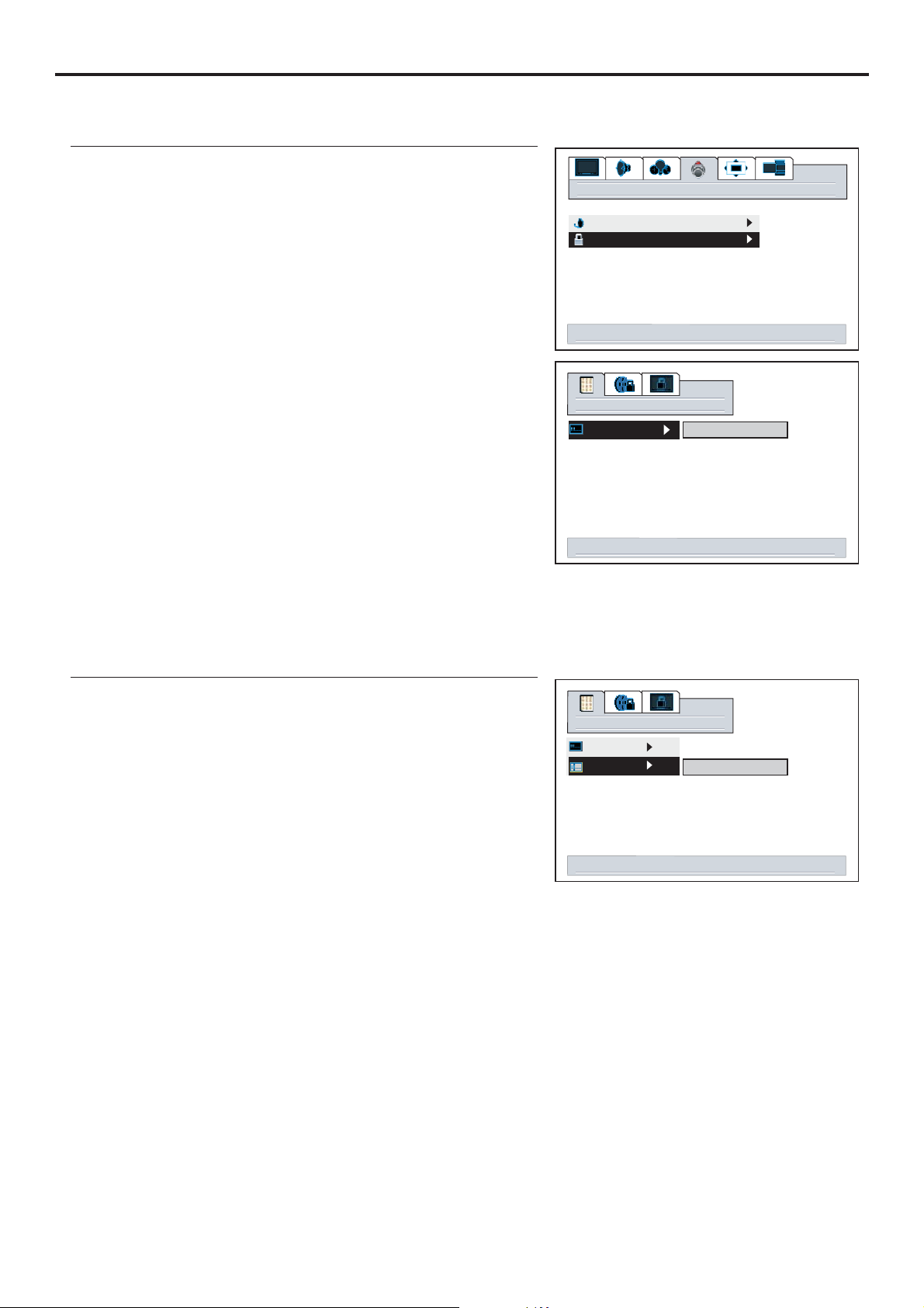
Adjusting Parental Control Settings (continued)
Accessing the Parental Control Menu
1
2
3
4
5
6
Use to move password digit leftward or
VOL+/-
rightward.
The default password is , you may change the
password yourself.
000000
7
The unit allows you to access the Parental Control menu if
you input the right password, or you will be denied.
options
tv tuner
content blocking
select to activate content blocking menu
password
enter
up/down change digit. right/left select digit
000000
OK
Changing the Password
1
2
password
enter
change
up/down change digit. right/left select digit
000000
OK
3
Be sure to write down your password and retain it for future use.
Note:
The unit provides a master password “666888”. If you forget your password and can’t access
Parental Control menu, you may input the master password to access Parental Control menu. Please
set a new password and make sure to remember your password.
39
Page 43
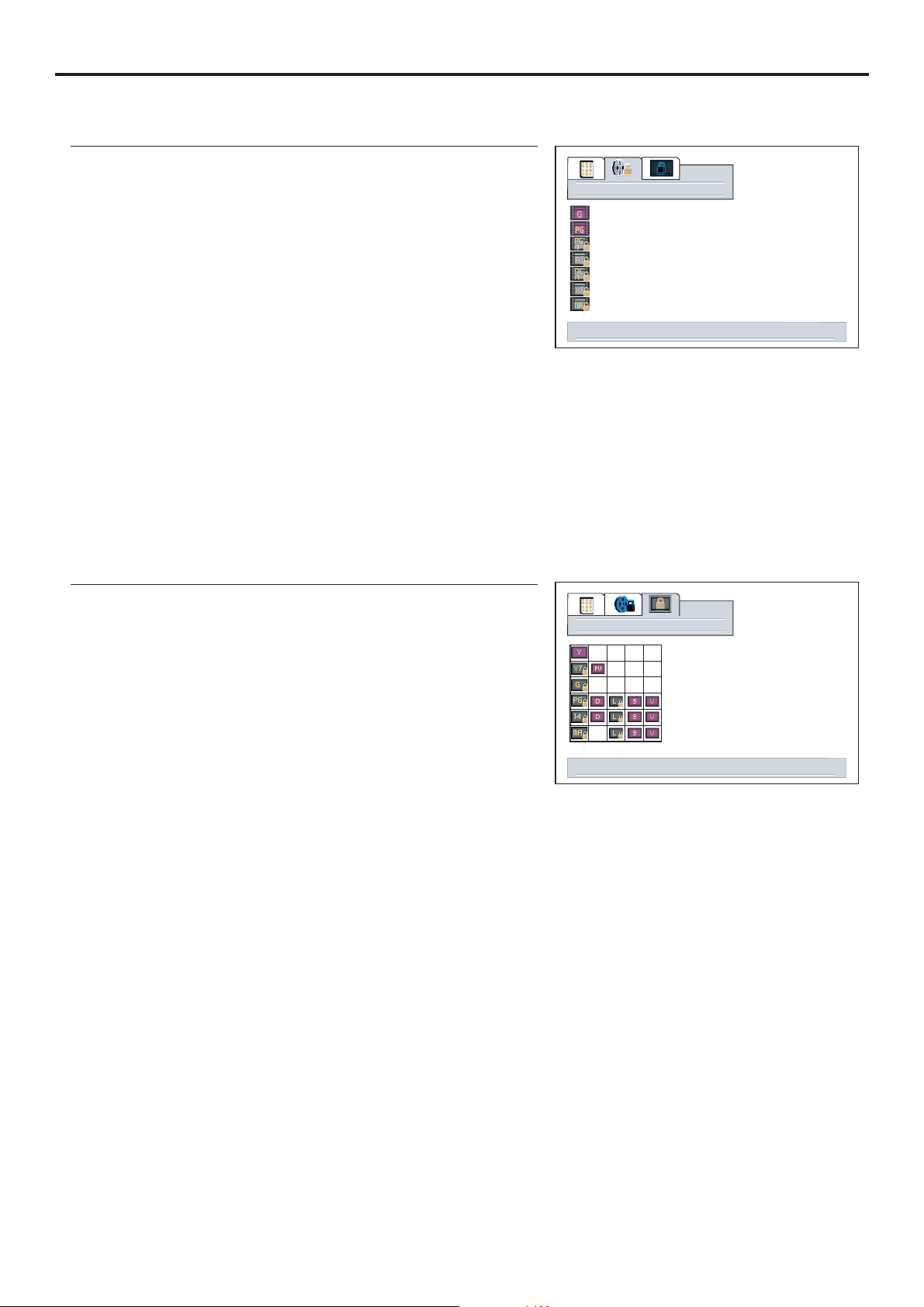
Adjusting Parental Control Settings (continued)
Adjusting the Movie Rating
1
Movie blocking
2
3
4
select to adjust movie blocking level, menu to return
5
“PG-13” in the age-based rating is blocked, this will
automatically block the higher ratings “R”, “NC-17”, “X”
How to unblock a Movie Rating
If you want to unblock a movie rating, please repeat steps 1~3 in [ ] and useAdjusting the Movie Rating
Adjusting the TV Rating
1
tv blocking
2
3
Press / or to select an age or content
4
rating to be blocked.
CH VOL+/-56
select to adjust tv blocking level, menu to return
5
When TV-Y7 in the age-based rating is set to BLOCK, this will automatically block the higher ratings:
TV-G, TV-PG,
TV-14 and TV-MA.
In addition, if you block “L” sub-rating in TV-PG, then the “L” sub-ratings in TV-14 and TV-MA will
Note:
Since a TV program may use either the MPAA rating or the TV Guidelines, both should be adjusted for
How to unblock a TV Rating
If you want to unblock a TV rating, please repeat steps 1~3 in [ ] and useAdjusting the TV Rating
40
Page 44
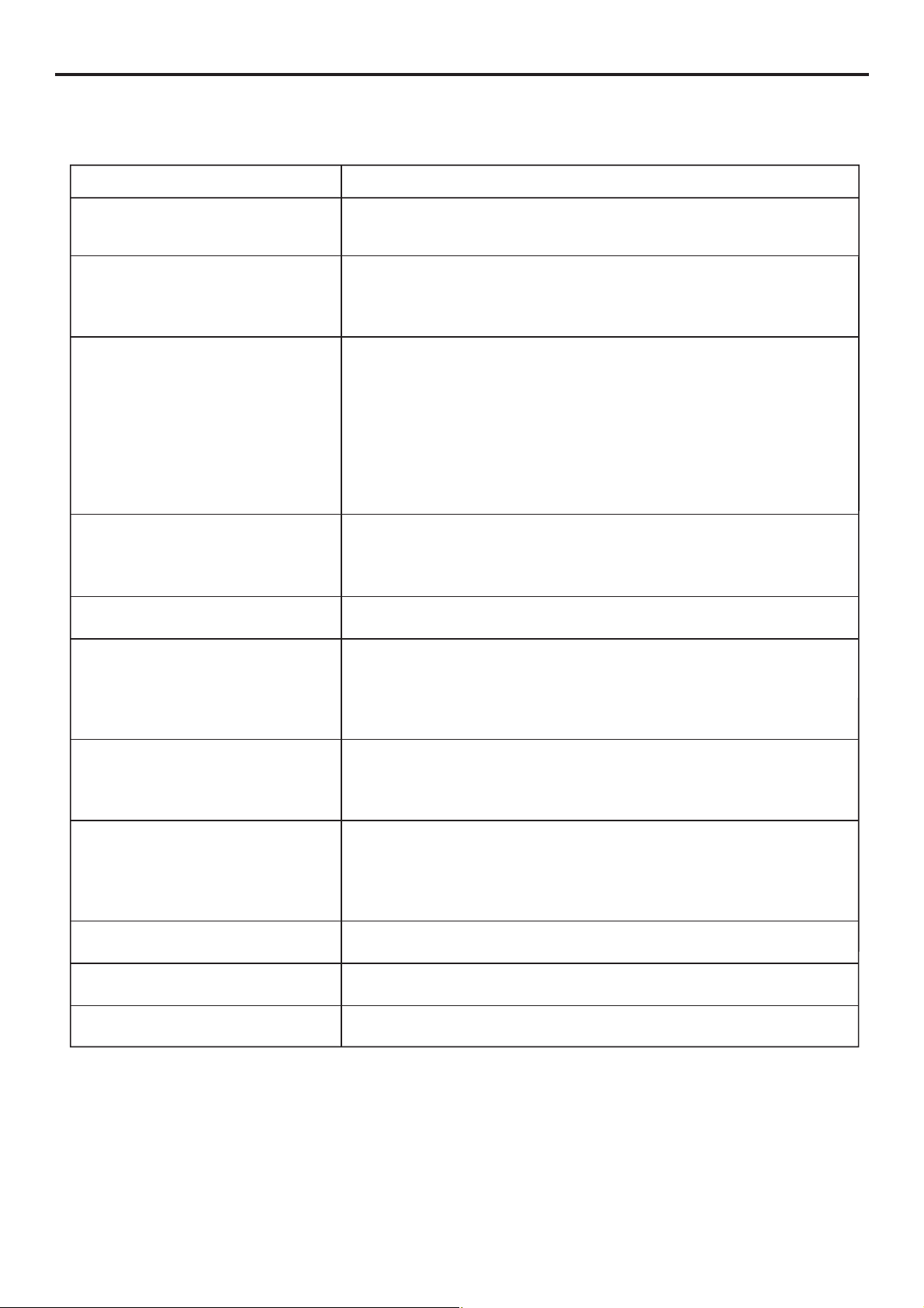
Troubleshooting
Before calling for repair service, check the following items for possible remedies to an
Symptoms
“Ghost” or double images
No power
No picture
Good picture but no sound
Good sound but poor color
Check item
!
This may be caused by obstruction to the antenna due to high
rise buildings or hills. Using a highly directional antenna may
!
Check that the AC power cord is plugged into the mains
socket.
!
Unplug the power cord, wait for 60 seconds. Then re-insert
!
Check antenna connections at the rear of the unit to see if it
is properly connected to the unit.
!
Possible broadcast station trouble. Try another channel.
!
Adjust the contrast and brightness settings.
!
Check the Closed Captions control. Some TEXT modes could
block the screen.
!
Select a correct input.
!
Is a non-compatible signal being input?
!
Increase the VOLUME.
!
Check that the unit is not muted.
!
Check Whether the sound is output to headphone
• Adjust the contrast, color and brightness
Poor picture
!
Sometimes, poor picture quality occurs when having
activated an S-VHS camera or camcorder connected and
having connected another peripheral at the same time. In this
case, switch off one of the other peripherals.
!
Horizontal dotted line
This may be caused by electrical interference (e.g. hairdryer,
nearby neon lights, etc.)
!
Turn off the equipment.
!
Television not responding to
remote control
Snowy picture and noise
No stable or not
synchronized VGA picture
Check whether the batteries are working. Replace if
necessary.
!
Clean the remote control sensor lens on the unit.
!
Do not use the remote control under strong or fluorescent
!
Check the antenna connection.
!
Check if you have selected the correct VGA mode in your
No output from one
of the speakers
Note:
If your problem is not solved, restart your TV by turning it off and then on
again once.
41
Page 45
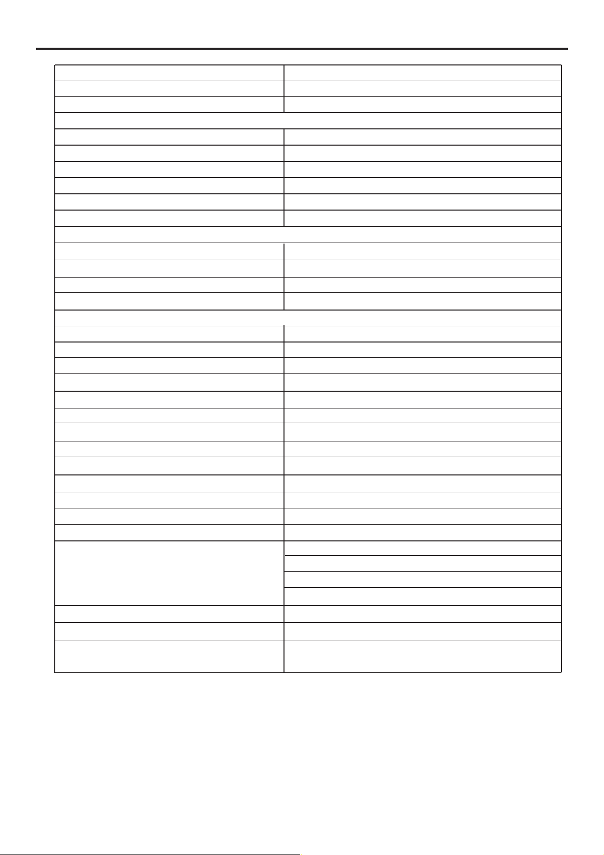
Specifications
Type PDP TV
Display Size diagonal 42” Wide
Geographical Version US
Display Feature
Resolution 852 X 480
Pixel Pitch 1.095 X 1.110 mm
Maximum Colors 16,777,000
Brightness 1000 nit
Contrast 3000:1
Viewing Angle 160 /160
TV Tuner & Color System
Tuner FST x 1
TV System NTSC
Channel Coverage VHF 2-13, UHF 14-69, CATV (1-125)
Video Features Progressive Scan
Audio Speaker System
Speaker Type Detachable
Maximum Audio Output 10Wx2
Stereo Sound System BTSC
Mount Support Wall Mount
Power Supply AC110-240V 50/60Hz
Power Consumption 400W
Stand by Mode Power Consumption 5W
Unit Weight (lb) 86
Unit Weight (lb) with Stand 81.5 (without speakers)
Unit Weight (lb) 70.5 (without Stand and speakers )
Unit Dimensions (WxHxD) (inch) 49 x 28.8 x 11.3
Unit Dimensions (WxHxD) (inch) with Stand 41.3 x 28.8 x 11.3 (without speakers)
Unit Dimensions (WxHxD) (inch) 41.3 x 25.4 x 3.1 (without Stand and speakers)
oo
Other Features Double Screen
Picture in Picture
Sleep Timer
Picture Freeze
Caption Closed Caption
Security Parental Control
Remote Control function support
for full OSD features
OSD Support English, French, Spanish
42
Page 46
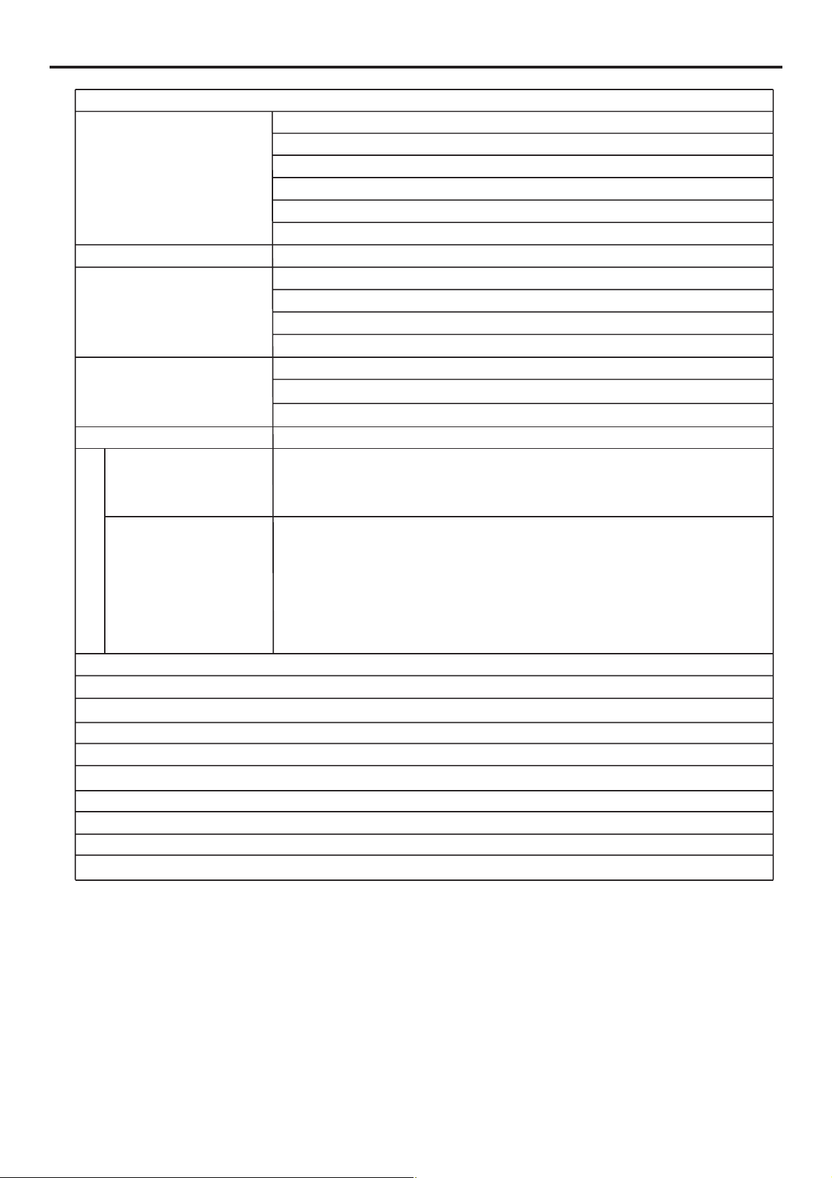
Terminals
Video In RF : TV/CATV 75ohms coaxial x 1
AV : RCA 75ohms composite video x 1
S-Video : 4-pin DIN x 1
D-Sub 15 x 1
DVI x 1
YPbPr/YCbCr (Support HDTV): RCA 75 ohms x 2
Video Out RCA 75 ohms
Audio In L/R RCA for S-Video or AV x 1
Stereo mini phone Jack for PC x 1
Stereo mini phone Jack for DVI x 1
Stereo mini phone Jack for YPbPr/YCbCr x 2
Audio Out L/R RCA for Video Out x 1
Headphone Jack : Stereo mini phone Jack x 1
Speaker Out x 2
Other RS232 x 1
Standard
Optional
Accessories
1 User Manual,
1 Remote Control,
1 Power Cable,
2 AAA Batteries,
1 PC D-Sub Signal Cable,
1 Component-Video Cable (YPbPr/YCbCr),
1 Audio/Video Cable
1 Audio Cable,
2 Speaker Cables
Specification (continued)
Display Format Supported by This Unit
For VGA: 640X480 @ 60Hz,72 ,75 ,85Hz Hz Hz; 800X600 @ 60Hz,72Hz,75Hz,85Hz;
1024X768 @ 60Hz; 1280X1024 @ 60Hz.
For DVI: 640X480 @ 60Hz,72Hz,75Hz,85Hz; 800X600 @ 60Hz,72Hz,75Hz,85Hz;
1024X768 @ 60Hz; 1280X1024 @ 60Hz.
For YPbPr: 480P @ 50Hz, 59Hz, 60Hz;
720P @ 50Hz, 59Hz, 60Hz;
1080i @ 50Hz, 59Hz, 60Hz.
43
Page 47
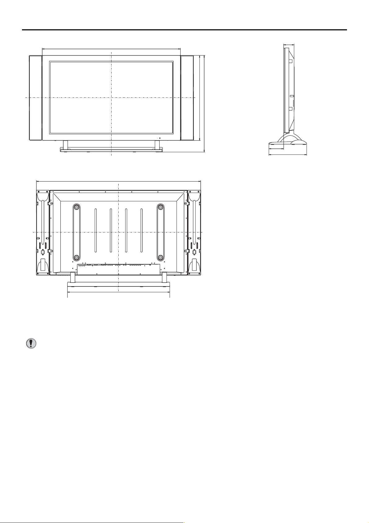
Dimensional Drawings
1050
1245
645
79
733
110
287
777
Design and specifications are subject to change without notice.
44
 Loading...