

Page 1

Primare Delay Box
Page 2

3
DELAY BOX
PREFACE
Copyright and acknowledgements
Copyright © 2004 Primare Systems AB.
All rights reserved.
Primare Systems AB
Renvägen 1
SE-352 45 Växjö
Sweden
Issue: Delay Box
The information in this guide is believed to be correct as
of the date of publication. However, our policy is one of
continuous development and so the information is subject
to change without notice, and does not represent a commitment on the part of Primare Systems AB.
Primare is a trademark of Primare Systems AB. All rights
reserved. All other product names are trademarks or registered trademarks of their respective owners.
2
FCC Warning: This equipment generates and can radiate radio frequency energy and if not installed and used
correctly in accordance with our instructions may cause
interference to radio communications or radio and television reception. It has been type-tested and complies with
the limits set out in Subpart J, Part 15 of FCC rules for
a Class B computing device. These limits are intended to
provide reasonable protection against such interference in
home installations.
EEC: This product has been designed and type-tested
to comply with the limits set out in EN55013 and
EN55020.
This guide was produced by Condesign Ljungby AB.
www.condesign.se
200448
DELAY BOX
Page 3

Welcome to the Primare Delay Box
The Primare Delay Box corrects lip sync errors in home
cinema systems by using a digital audio (S/PDIF) signal.
The Primare Delay Box is connected between the digital
audio (S/PDIF) of your DVD (or similar). The unit delays
the digital audio signal by a time of your choice. This
results in a perfect sound and picture synchronisation.
Intuitive user interface
In keeping with the philosophy of the Primare range of
systems, the Delay Box can be controlled through a very
simple and intuitive set of front panel controls.
Alternatively all the functions of the Delay box can be
controlled by the Remote Control supplied with the Delay
box.
INTRODUCTION
Modern displays, such as plasma screens, LCD screens and
projectors use sophisticated imaging processors to produce the
best picture possible. This processing takes time and produces
a delay in the picture display. In bad cases sound can be heard
before the image. This is called a lip-sync error.
Technical performance
The Delay Box is is capable of full conversion between a
coax and an optical signal.
E. g. any input signal to coax will be available from
both outputs (coax and TOSlink), as any input signal to
TOSlink will be available from both outputs.
You choose the type of input signal that will be available
by means of button 1 and 2 on the front panel.
Note! No conversion is carried out when the delay box is
in BYPASS mode.
DELAY BOX
3
Page 4
5
DELAY BOX
CONNECTING THE DELAY BOX
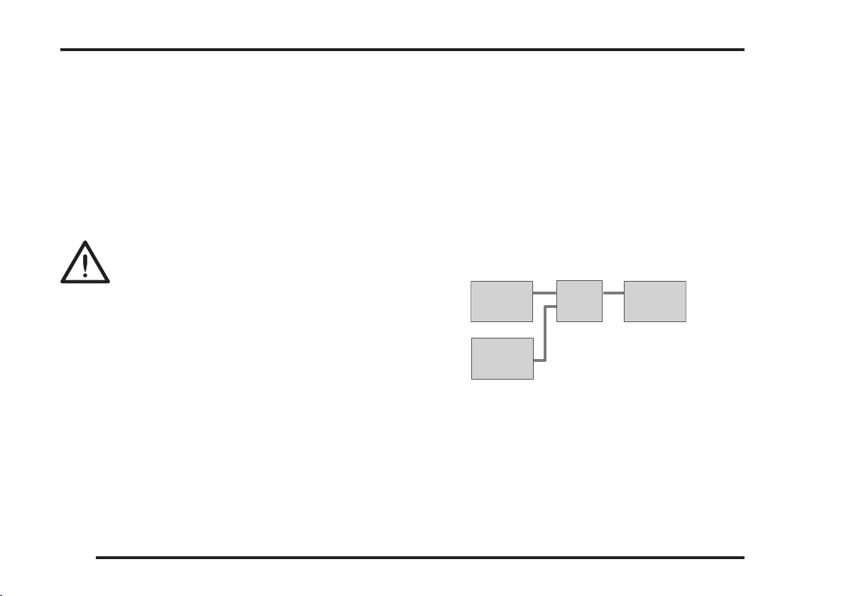
DVD26 SPA21
Delay
box
Digital
source
This chapter provides a quick overview of how to connect the
Delay Box to other components in your system.
Power connection
Warning: Before connecting power, check that
the required supply voltage, indicated on the
AC/DC-adapter, corresponds to your local
AC supply. If a different voltage is stated on
the type plate do not connect the Delay Box to the mains
power, and seek advice from your dealer.
Connect the mains power using the enclosed mains cable
(transformer).
NOTE: Always disconnect the Delay Box and all other
units in the system from the mains power before connecting or disconnecting any of the cables. This might
seriously damage the unit.
Safety instructions
To prevent re or shock hazard, do not expose this
appliance to dripping or splashing. No objects lled with
liquids, such as vases, should be placed on the Delay Box.
4
Connecting the Delay Box in your
system
• Connect the digital audio coax cable (S/PDIF) or
optical cable (TOSlink) from the DVD or other sorce
into the INPUT of the Delay Box.
• Connect another digital audio (S/PDIF) coax cable or
optical cable (TOSlink) from the Delay Box OUTPUT
to the amplier.
DELAY BOX
Page 5
CONNECTING THE DELAY BOX
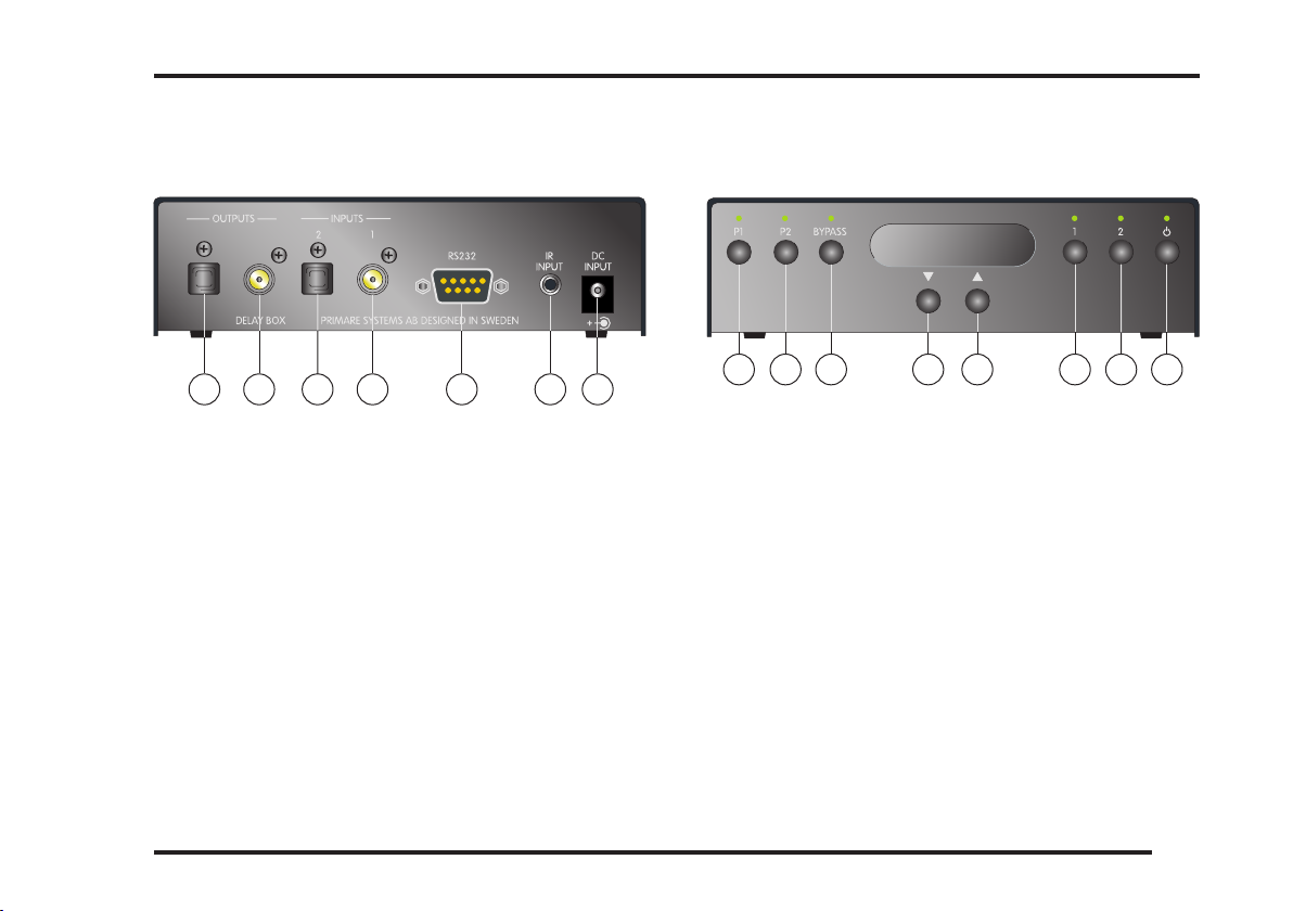
Back panel connections
A
C
B
D
E
A. Optical, TOSlink, output
B. Coax, SPDIF, output
C. Optical, TOSlink, input
D. Coax, SPDIF, input
E. DATA (RS232) input for home installation
F. IR/input
G. Main power input (12V)
Front panel display
L
G
F
H
J
I
K
N
M
O
H. Preset 1
I. Preset 2
J. Bypass
K. Decrease delay time in milliseconds
L. Increase delay time in milliseconds
M. Input 1 (coax digital audio)
N. Input 2 (TOSlink)
DELAY BOX
O. Standby
5
Page 6
7
DELAY BOX
OPERATING THE PRIMARE DELAY BOX
Mains ON
• Plug the lead from the power adapter into the Primare
Delay Box and the other end into a wall socket.
The stand by indicator will light up and the Delay Box is
ready for operation.
To switch on from standby or to standby
• Pressing on the front panel or on the remote
control, will change the standby mode.
Infra-red remote control
The Delay Box is fully controlled by an infra-red remote
control.
IR-back
The Delay Box can also be controlled by using the
IR-input at the backpanel. Make sure that the Delay Box
is in standby mode.
• Hold down button 2 on the front panel and press .
The standby indicator will blink –2–.
• Hold down button 1 on the front panel and press to
restore the IR-input to the front. –1– is displayed for a
couple of seconds.
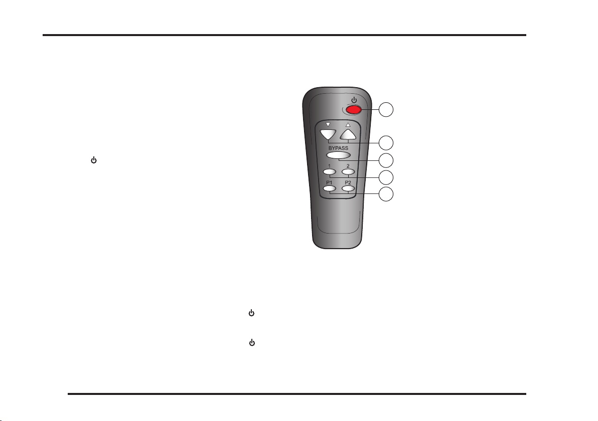
The Remote Control
A
B
C
D
E
To dim the front panel display
• Simultaneously press button 1 and 2 on the front panel
for two seconds. The display will dim.
When adjusting any values the display will temporary
light up for a couple of seconds.
• Simultaneously press button 1 and 2 on the front panel
for two seconds to restore the Delay Box from dim mode.
A. Standby ON/OFF
B. Increase/decrease
delay time in
milliseconds
C. Bypass
D. Input 1 and 2
E. Preset 1 and 2
6
DELAY BOX
Page 7
OPERATING THE PRIMARE DELAY BOX
Determining a delay value
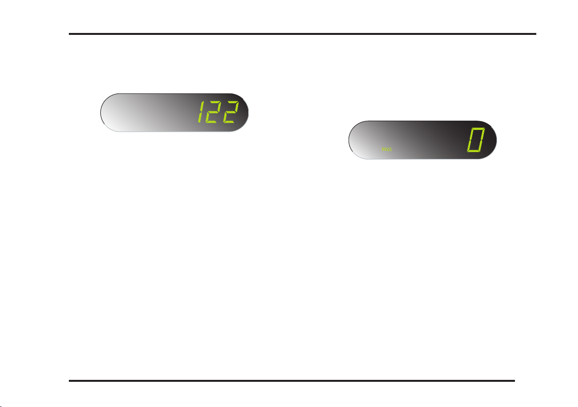
The amount of delay is presented on the front panel display as soon as the Delay box is connected in the system.
• Press button 1.
Use the buttons p and q on the front panel or the
remote control to select a required delay time.
• Press button 2.
Use the buttons p and q on the front panel or the
remote control to select a required delay.
The delay time value steps one millisecond at a time until
the nearest ten. Then it steps 10 milliseconds at a time
untill the nearest hundred and thereafter it steps a hundred at a time up to 600 milliseconds. The time delay value
counts down in the same way.
Presetting a delay value
• Press button P1 for 3 sec. The indicator will blink three
times and the preset value is stored.
• Press button P2 for 3 sec. The indicator will blink three
times and the preset value is stored.
Bypass
Automatic bypass
The unit detects 44,1 kHz sampling rate from a standard
compact disc and switches automatically into bypass
mode.
Manual bypass
If delay is wanted for 44,1 kHz sampling rate:
• Press and hold the BYPASS button on the front
panel for a couple of seconds. The indicator will ash
three times.
Use the buttons p and q to increase or decrease the
delay time.
• To restore automatic bypass, press and hold the
BYPASS button on the front panel again.
The indicator will ash two times.
DELAY BOX
7
Page 8

 Loading...