

!
!
!
!
!
INSTALLATION AND USER MANUAL
SPIDER230 RADIO TELESCOPE
VERSION 1.1
Update 28-07-2014
!
This instrument is made by PrimaLuceLab iSrl, via Roveredo 20/b, 33170 Pordenone (Italy). For any questions con-
cerning the use, support and warranty information, please refer to the addresses given in the relevant documents.!
PrimaLuceLab iSrl • Via Roveredo 20/B, 33170, Pordenone • www.primalucelab.com

PrimaLuceLab iSrl Spider230 user manual
English
CAUTION
To avoid the danger of electric shock and malfunctions, do not expose the radio telescope (in particular the mount and the recei-
ver) to rain or moisture. The electronics are not waterproof so in case of bad weather conditions with rain, snow or similar, it is
required to keep the instrument closed and covered with a special waterproof cover.
Do not use the radio telescope in case of strong winds (above 25 km/h) to prevent unwanted movement of the antenna, dama-
ge to support system, handling equipment and antenna. If the wind speed exceeds 25 km/h, please keep the radio telescope
pointed towards the vertical (zenith) and enclosed in a special protective structure.
!
WARNINGS
If handled improperly, the radio telescope can be damaged, then please follow the instructions below:
- Do not disassemble the closed radio telescope components such as equatorial mount or receiver
- Do not open or subject to damage shock or excessive shock any electronic parts. For example, do not drop the receiver or other
elements.
- Do not short circuit the electronic elements
- Do not expose the instrument to extreme temperatures, above 50°C
- Do not incinerate or dispose in fire any component of the radio telescope
- Do not wet any electrical or electronic part of the radio telescope
- Do not bend, change or force any mechanical part of the radio telescope
!
POWER SUPPLY
The Spider230 radio telescope has components that require an external power supply: mount and receiver. Do not wet, open or
modify the power supply supplied with the instrument. Immediately unplug the power supply if there is any malfunction.
!
"
"Skywatcher" is a registered trademark of Synta Optical Technology corp.
!
!
The Spider230 radio telescope has a 8x50 optical finder for the control of positioning and automatic tracking of the pointing
system. Do not look at the Sun (or other strong light sources) without the appropriate filter package!!
"
!
!
page !1
TRADEMARKS
WARNING

PrimaLuceLab iSrl Spider230 user manual
Index
Verification of components supplied 3
Parts identification 6
Installation: pier 7
Installation: mount 9
installation: antenna 13
First use: mount polar alignment and finder alignment 30
First use: mount alignment 36
First use: antenna setup 38
RAL10PL receiver 41
RadioUniverse control software installation 45
Advanced functions: record a transit 50
Advanced functions: record a radio-picture 53
Advanced functions: performances optimization 56
Advanced functions: create a radio-map with RUviz 60
Experiments: the Sun, radio waves source 63
"
!
!
page !2

PrimaLuceLab iSrl Spider230 user manual
Verification of components supplied
Check for the presence of all the components required on the ordering. The included accessories and parts will vary
depending on the order.
!
!
!
!
!
!
!
!
!
!
"
!
!
page !3
4 quarters of parabola
Support device"
for equatorial mounts
Tie rods supporting
block
2 5Kg counterweights
for Declination axis
1 support plates with 3
holes
3 support plates with 4
holes
4 support rods for feed horn"
(1169mm long)
2143587
3 rear tie rods (2 1422mm long, 1
1453mm long)
6
PrimaLuceLab iSrl Spider230 user manual
!
!
!
!
!
!
!
!
!
!
!
"
!
!
page !4
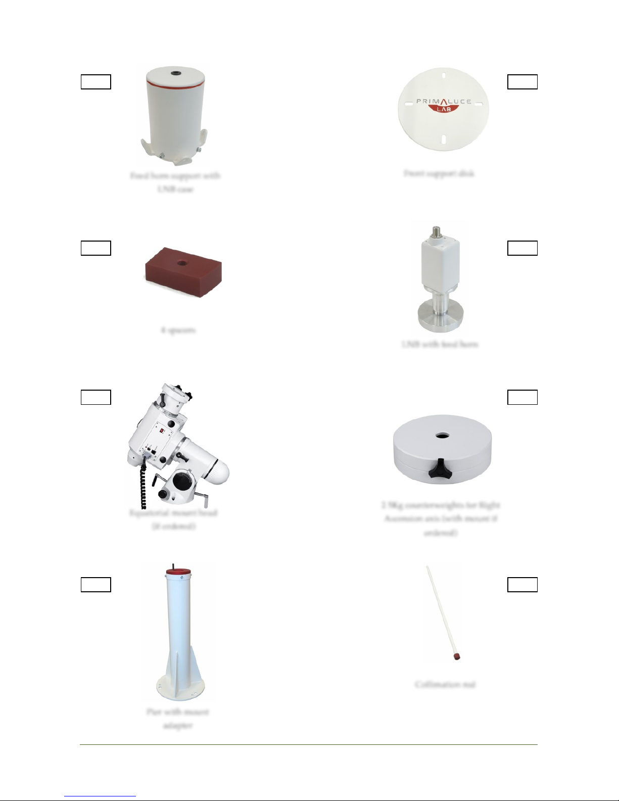
Front support disk
4 spacers
LNB with feed horn
Collimation rod
Equatorial mount head
(if ordered)
2 5Kg counterweights for Right
Ascension axis (with mount if
ordered)
Pier with mount"
adapter
1091211141316
15
Feed horn support with
LNB case
PrimaLuceLab iSrl Spider230 user manual
!
!
!
!
!
!
!
!
!
!
"
!
!
page !5
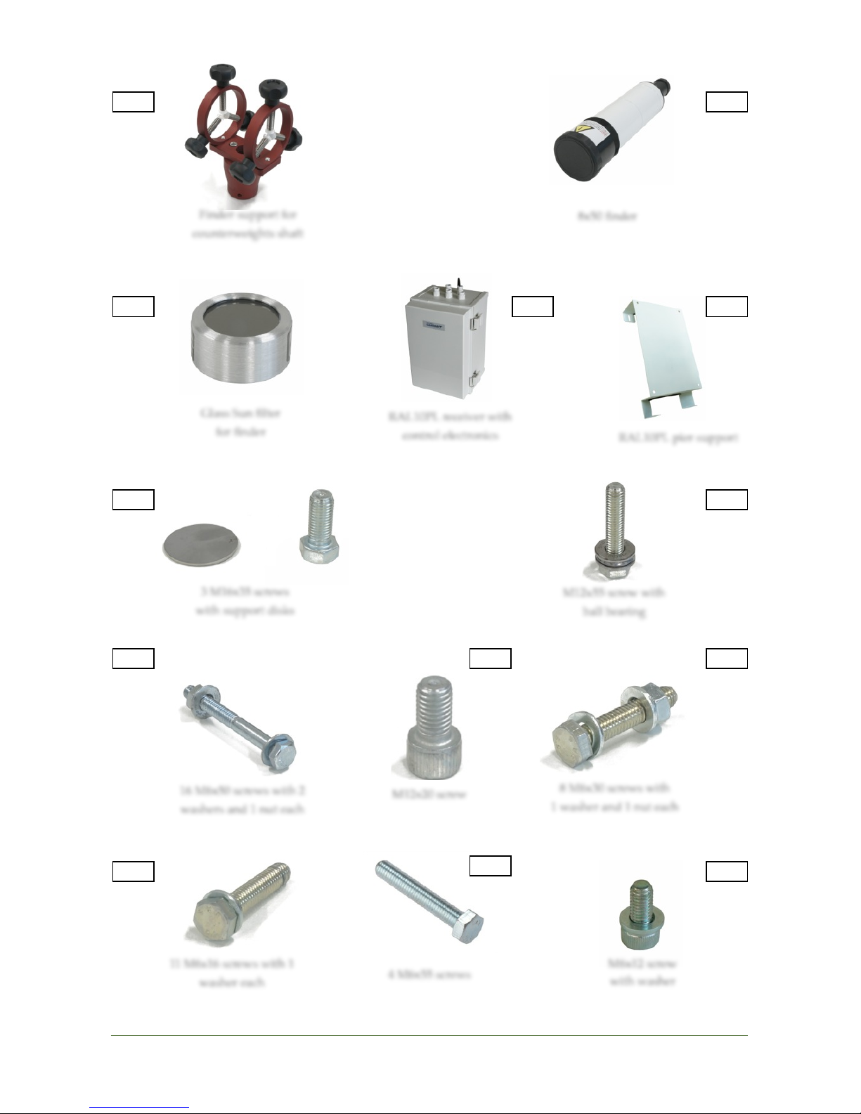
8x50 finder
Glass Sun filter"
for finder
RAL10PL pier support
3 M16x35 screws"
with support disks
M12x55 screw with"
ball bearing
16 M6x50 screws with 2
washers and 1 nut each
8 M6x30 screws with"
1 washer and 1 nut each
11 M6x16 screws with 1
washer each
18
17
21
19
2322262427
29
Finder support for
counterweights shaft
M12x20 screw
25
28
4 M6x55 screws
RAL10PL receiver with
control electronics
20
M6x12 screw"
with washer
PrimaLuceLab iSrl Spider230 user manual
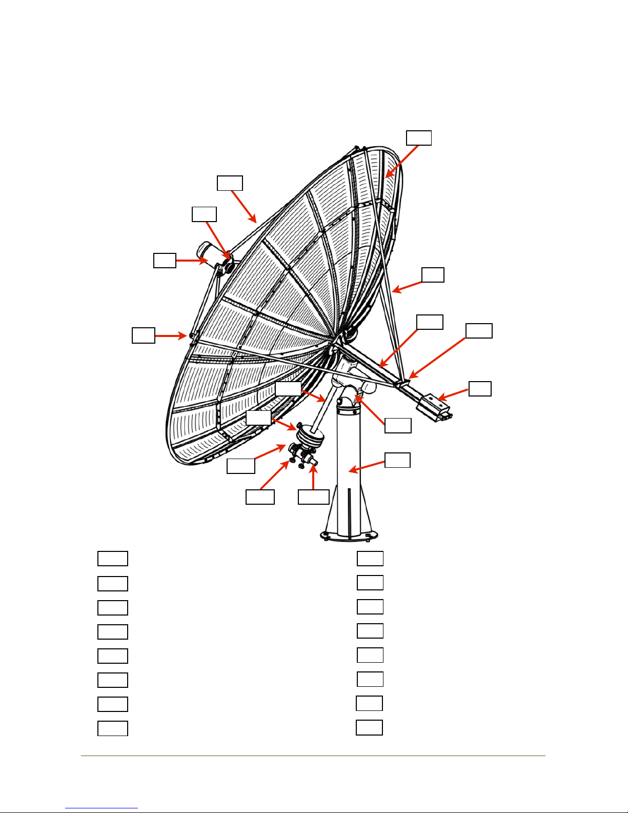
Parts identification
The numbers indicate the name of the component listed below. Read the following sections for details on opera-
tion.
!
"
!
!
page !6
1
5129461817191413142012344 installed quarters of parabola
Support device for equatorial mounts
Tie rods supporting block
2 5Kg counterweights for Declination axis
5
Support rods for feed horn
67Rear tie rods
Support plate with 4 holes
9
Feed horn support with LNB case
12131415LNB with feed horn
Equatorial mount head
17
Finder support for counterweights shaft
18
8x50 finder
32719Glass Sun filter for finder
30
Right Ascension counterweights shaft
Pier with mount adapter
2 5Kg counterweights for Right Ascension axis
PrimaLuceLab iSrl Spider230 user manual
!
Installation: pier
!
The first part of the radio telescope to be installed is the pier (15) which supports the mount (13). The pier must be
installed on a platform. This can be made of wood or concrete, in the latter case you need to verify the correct hori-
zontal level and you can set the pier using special threaded rods to be inserted into the concrete base. Before star-
ting the installation, make sure that the concrete base has completely hardened.
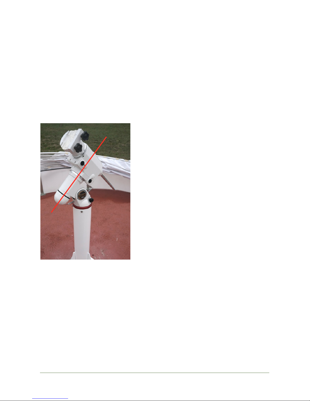
Identify the center of the concrete platform and place the pier
slightly to the West : its axis should be about 20 cm to the West of
the center of the platform. Then put the pier on the outlined point.
Before attaching the pier to the concrete base, it is necessary to
have a rough idea of the North direction (to properly perform the
following mount polar alignment). If you are installing in the dayti-
me (so you cannot see the North Star that indicates the North ), a
compass can help you. At this time it is not necessary to perform a
precision alignment since later, when the pier will be fixed, it will be
possible to adjust the mount position (with a maximum displace-
ment of about 15 degrees). Unscrew the 4 screws around the pier,
remove the red adapter and now connect this under the mount (as
explanations on page 8) and put it all on the column. The correct
direction is the one shown, in the photo at left, by the red line (cor-
responding to the mount polar axis). Rotate the entire mount with
column until the axis pointing North, so mark, for example with a
piece of chalk, the position of the fixing holes to be done ( at the base of the column).
Remove the mount from the pier and then move the pier. Perform in the predetermined points of the concrete base
about three 20mm diameter holes to penetrate for approx. 3/4 the thickness of the concrete platform (for a preli-
minary design of the concrete base you can look at Appendix A).
Insert the threaded rods (not included in the packaging of the radio telescope as they depend on the type of base
that you want to create). Depending on the type of bar installed, you can fix with a two chemical anchoring compo-
nent such as silicone (to be injected with a grease gun) and then enter the pier in the threaded rods.
!
"
!
!
page !7
PrimaLuceLab iSrl Spider230 user manual
!
!
!
!
!
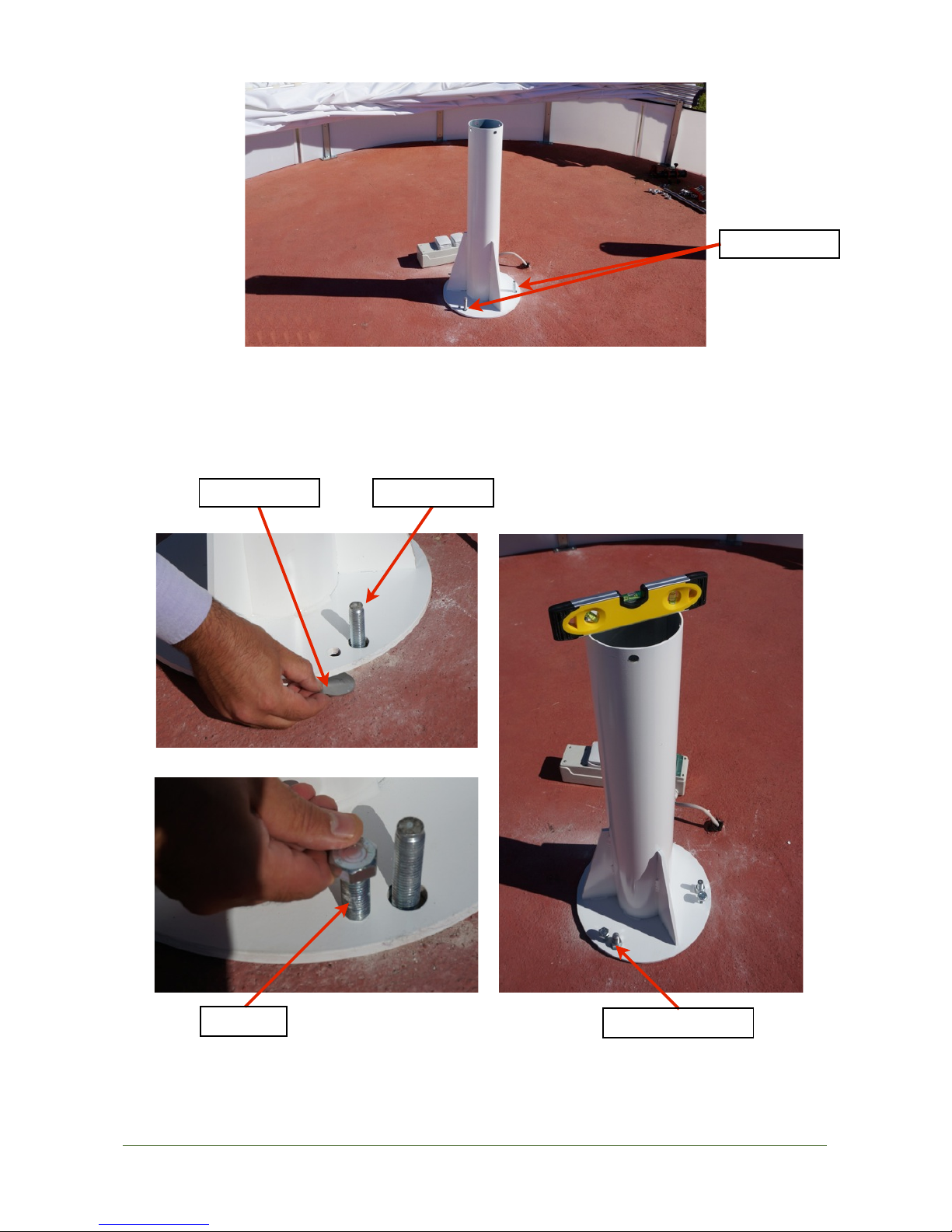
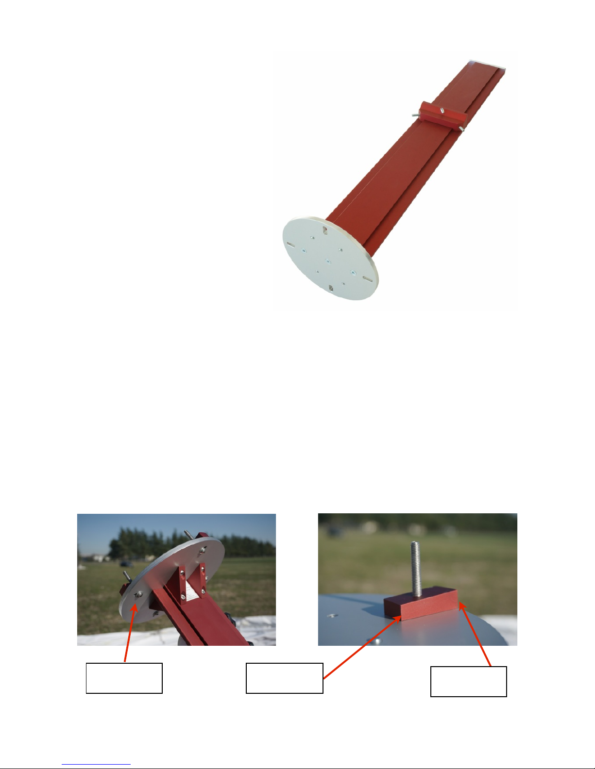
Placed underneath the smaller hole near the bar one of the 3 support disks (21). Screw the M16x35 screws (22)
that you can tighten to perfectly horizontal adjust the pier with the aid of a bubble (photo below-right). When the
pier is leveled, secure it by inserting and tightening the 3 nuts on the 3 threaded rods.
!
"
!
!
page !8
Support disk
M16 screw
Threaded rods
Nut for threaded rod
Threaded rod
PrimaLuceLab iSrl Spider230 user manual
!
Installation: mount
!
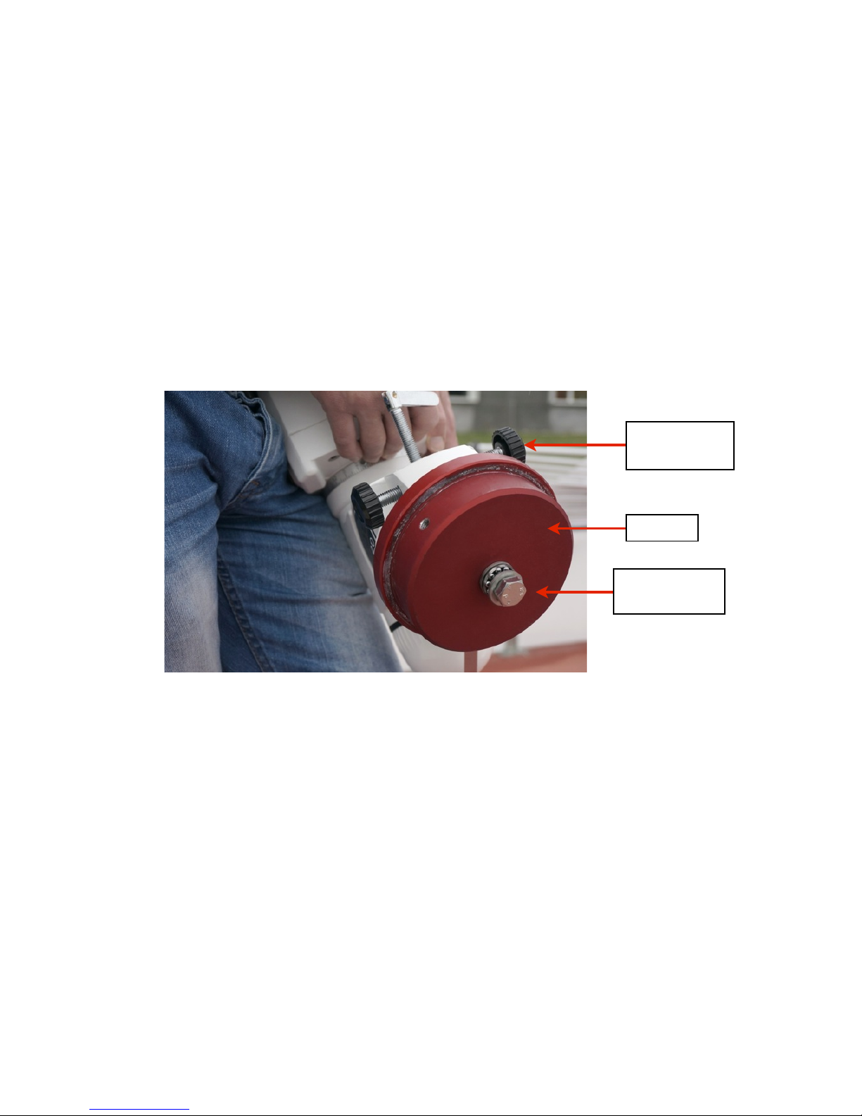
With the pier installed, we can now proceed with the installation and preparation of the mount head (13). Unscrew
the 4 screws, sideways, blocking the red flange on the pier and put it under the mount (remember to loosen the
azimuth adjustment screws to allow the mount itself for a perfect flange join). Then take the M12x55 with the ball
bearing locking screw (23): insert the ball bearing in the screw and then tighten it under the plate. Caution: do not
overtighten (eg with a wrench) this screw otherwise the mount will fail to move left or right with the provided
micrometric azimuth movement when you need to perform a precision polar alignment.
"
!
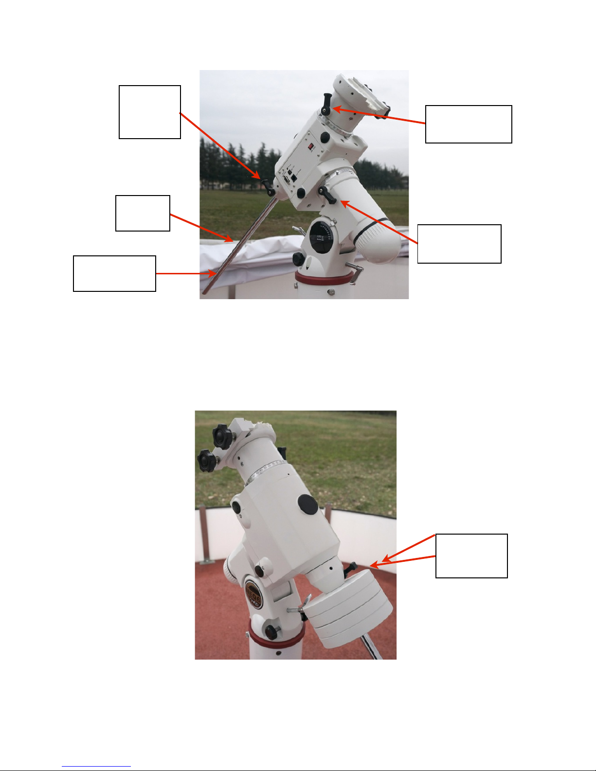
Then enter the mount head (13) with the installed flange on the pier and secure it with the 4 locking screws pre-
viously loosened. Loosen the locking screw of counterweights bar and pull down the counterweight shaft itself.
Now you can open the clutches of the two mount movements (Right Ascension and Declination) so being able to
rotate freely. Right Ascension (RA) axis is the one used by the mount for tracking objects in the sky while the Decli-
nation (DEC) is operated for the move. Each axis has a clutch that stops the mount movement and the mount mo-
tors work only when the clutches are closed.
!
!
"
!
!
page !9
Flange
M12 screw with ball
bearing
Azimuth regulation
screws
PrimaLuceLab iSrl Spider230 user manual
!
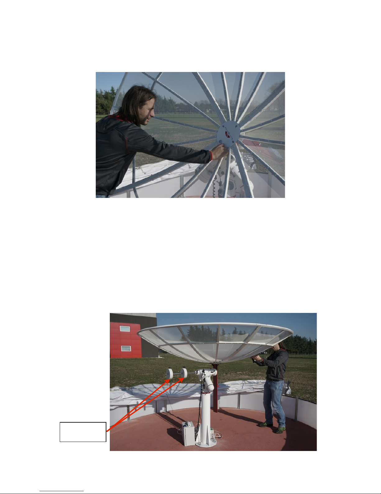
Bring the mount to the so-called HOME position (the mount points North with counterweights bar pointing down)
and screw on the counterweights bar the short extension bar (you can find in the mount case). Insert the two 5Kg
white counterweights (14) and then stop at the top of the bar closing their black screws (note: make sure they are
locked and do not move on).
"
!
!
!
!
"
"
!
!
!
!
!
!
"
!
!
page !10
2 5Kg counter-
weights for Right
Ascension
Clutch for Declination
axis
Counterweights
bar locking
screw
Counter-
weights bar
Clutch for Right
Ascension axis
Extension rod for
counterweights bar
PrimaLuceLab iSrl Spider230 user manual
Using a German equatorial mount, the Spider230 radio telescope needs to be aligned to the North Star: thus it’s
needed to make fine alignment adjustments during the night. It’s still possible to start with a rough alignment even
during the day. In order to do this, it is necessary to know the latitude of the place where the radio telescope is in-
stalled: if you do not know you can, for example, visit Google Maps - maps.google.com - and enter in the search
field at the top of the page the address and city where you installed the instrument. Then click with the right mou-
se on the map (the point where the instrument is installed) and select "What's here?". The coordinates will automa-
tically appear in the search box. The first number indicates the latitude. For example, if it appears:
!
45.992952,12.635844
!
then the latitude is almost 46 degrees.
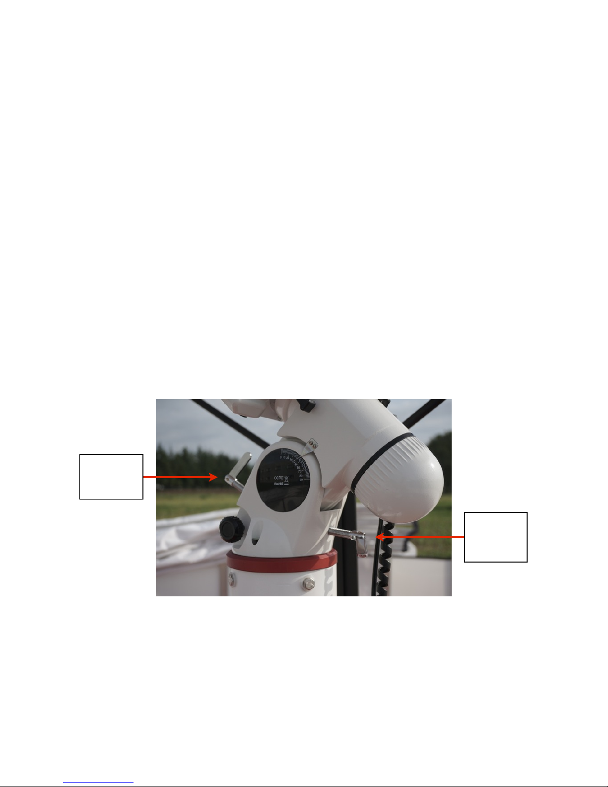
Now set the latitude in the mount and adjusts with the adjustment screws. The way this is done depends on the
type of equatorial mount used: if you use the N-EQ6 SynScan, find the two latitude adjustment screws in the lower
part of mount, closest to the pier (if used another type, read the manual of your mount). If there are two opposite
screws, unscrew a screw and screw the other, as in the photo shown here of the N-EQ6 SynScan mount.
!
!
!
!
!
Now we need to check that the polar axis of the mount is correctly pointing to the North. This procedure should be
performed with precision during the night time (pointing to the North Star) but you can get a temporary alignment
even during the day. For this setting you need to use a compass.
"
!
!
page !11
Latitude"
adjustment"
screws
Latitude"
adjustment"
screws
PrimaLuceLab iSrl Spider230 user manual
Recall that the needle of a compass points the magnetic North Pole (the Earth's magnetic field) and not the geo-
graphic North (taking as a reference the North Pole). Magnetic North is currently in the Canadian Arctic Archipelago,
it’s not still and it changes position over time. So the compass needle, depending on where we are on Earth, will be
moved eastward or westward with respect to the geographic North. The angle between the direction of magnetic
North and the true North is called magnetic declination. You can check the current magnetic declination from the
world map of magnetic declination updated to 2010 found in the web page:
"
http://www.ngdc.noaa.gov/geomag/WMM/data/WMM2010/WMM2010_D_MERC.pdf
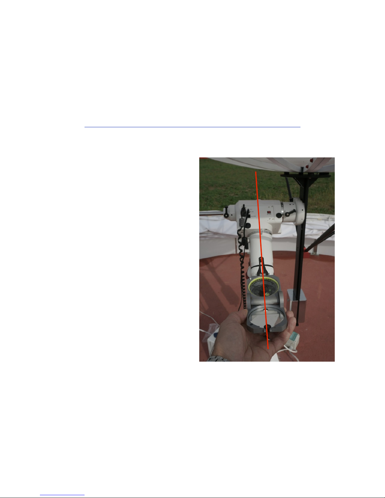
To correctly point true north with a compass, you have to
subtract to 360° the magnetic declination of your place
of observation: this will be the direction of the North. For
example, in Italy we have a magnetic declination East (ie
positive) by about 2 degrees. The compass will indicate
true north when the compass needle will be pointing not
at 360° but at 358° (360-2 = 358).
So take the compass, position yourself just behind the
mount and rotate to make it point to the correct direction
of true North (the red line in the photo at right). In this
way, having also set the latitude as we have seen before,
the polar axis of the mount will be pointed towards the
North Star with sufficient accuracy. We will read how to
make a precision polar alignment (during the night, th-
rough the polar scope that came with the mount itself)
on page 32 of this manual.
!
"
!
!
page !12
PrimaLuceLab iSrl Spider230 user manual
installation: antenna
!
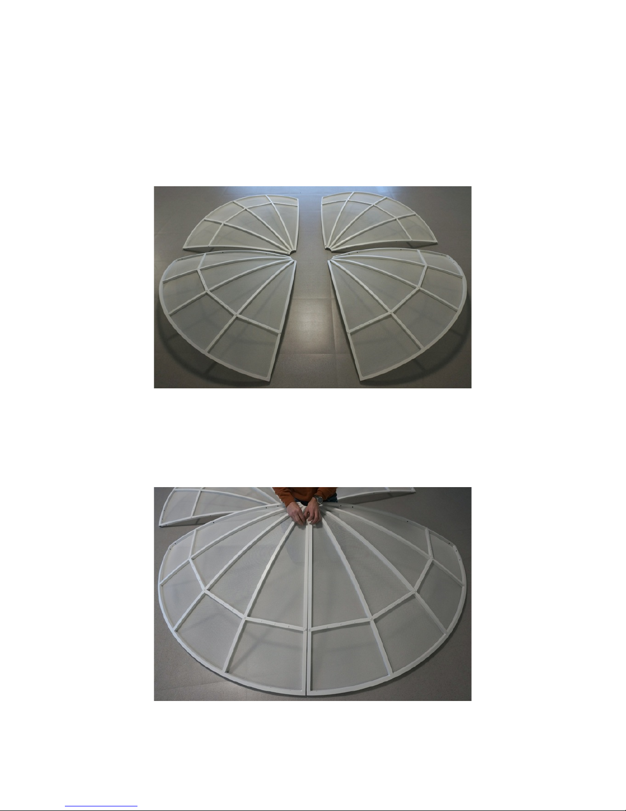
Spider230 has a parabolic antenna that consists of 4 sections (quarter of parable - 1). First of all you need to build
the reflector (primary reflector): put on a plane the four quarters (1) and push them together two by two, as in the
photo below.
"
Then use the 16 M6x50 screws with 1 nut and 2 washers each (24) to tie together two quarters of the parabolic
antenna, inserting them into the holes (4 on each side of the ray). Close the screws with bolts but do not tighten at
all, you will need to tighten them later.
"
!
!
page !13

PrimaLuceLab iSrl Spider230 user manual
In doing so, make sure that the two coupled quarters to mate best as possible, avoiding small steps between one
and the other in the forward facing part of parabolic antenna (to get a better parabolic shape).
!
Then approached the two halves of the parabolic antenna.
!
!
"
!
!
page !14
PrimaLuceLab iSrl Spider230 user manual
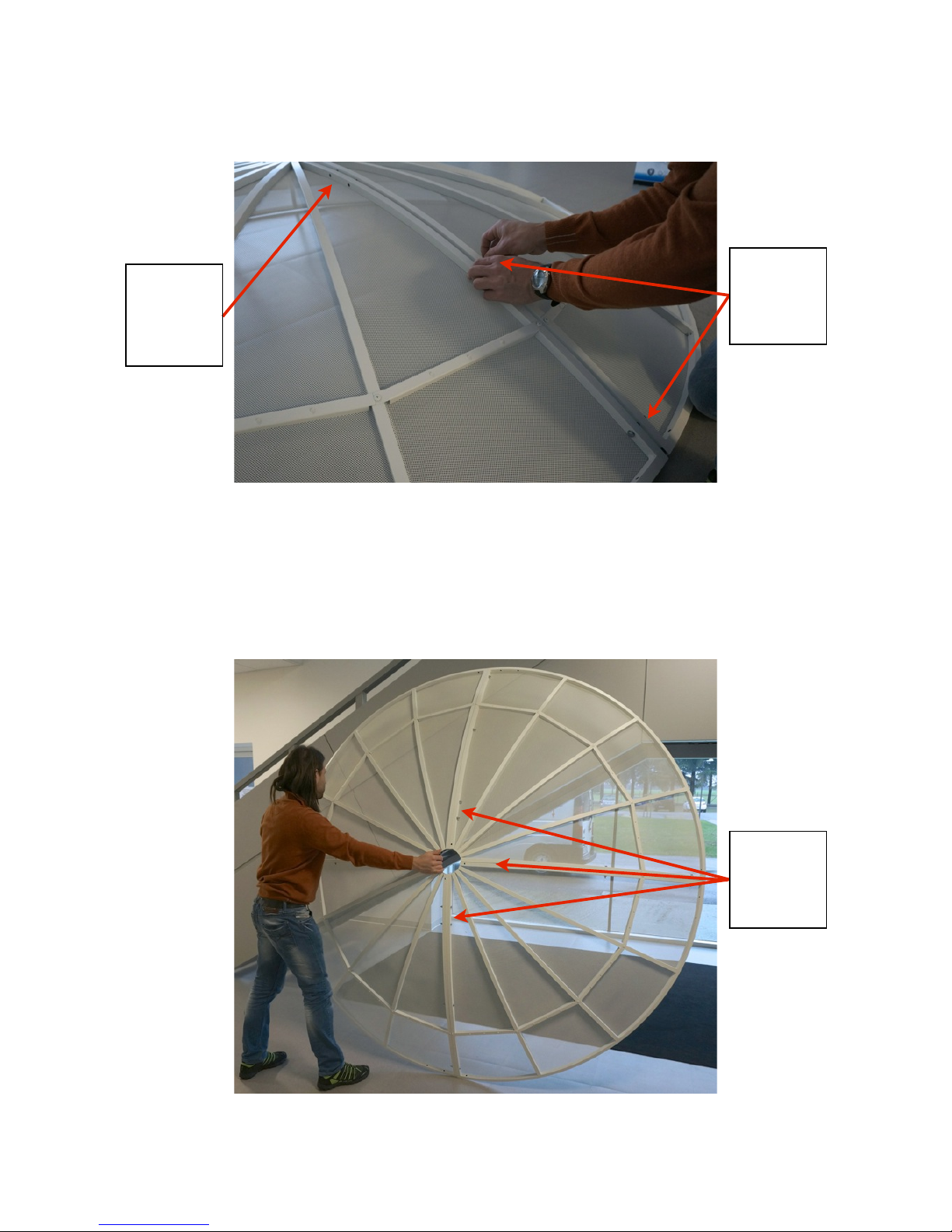
Tighten first the two top screws for each half (the outer ones - photo below). As before, use the screws with bolts
but do not tighten completely, it will be necessary to tighten them later.
!
Then raise the parabolic antenna and, with the aid of a second person or a vertical table top, insert and tighten the
screws in the two holes for each ray to the center of the antenna.
"
!
!
page !15
First, insert the
screws through
the 2 holes in
the outer radius
Put the screws
in these holes in
the next step
Insert 2 screws
through the
two holes in the
inner radius
PrimaLuceLab iSrl Spider230 user manual
Now take the support device for equatorial
mounts (2) of the parabolic antenna. It’s already
preassembled with the connecting plate for the
antenna. Unscrew the two screws on the bot-
tom plate by removing the end of the bar. Now
insert, by sliding from the lower part of the plate
one of the 2 5Kg counterweights for Declination
axis (4) and secure it at the bottom of the plate
by tightening the two locking screws (make sure
it does not move). Then screw the back plate at
the end of bar.
!
!
!
!
!
Then place the support device for equatorial mounts (2) onto the upper part of mount head (13) and close the 2
knobs lock on the side. Make sure that the plate is tight and does not move. Insert the 4 M6x55 screws (28) in the
front disc and attach by screwing, as in the image below, the 4 spacers (11 - one for each screw). The spacers have
a variable thickness with a side less thick: this goes toward the center of the support disc (in fact it fits to the shape
of the parabolic reflector). Do not tighten all the screws of the spacers but leave slightly open to allow you to move
the screw along the slot of the circular plate (used to attach the plate to the antenna more easily).
!
!
!
!
"
!
!
page !16
Less thick side
More thick side
M6x55 screws
PrimaLuceLab iSrl Spider230 user manual
To adjust the position of the 4 just inserted screws (to fix the spacers) sliding them in the slot, you can help by in-
serting the front support disk (10) and slide the screws until they pass through the holes of the disc itself. Then
remove the front support disk.
!
Now proceed with the parabolic reflector installation. This procedure must be done at least by 2 people but, for
simplicity, we recommend that you run it in 3. Lift carefully the entire reflector and, making sure not to damage the
parable itself, place it right in front of 4 spacers (11) that you have previously installed. Match the 4 central holes
(90° apart) with the 4 screws and pull down until the reflector touches the 4 spacers. Due to the large size of the
parabolic antenna, this step may be difficult: execute it carefully helping the insertion of the reflector impressing
small vibrations.
!
!
"
!
!
page !17
Front support"
disk
Parabolic antenna holes for
screws insertion
PrimaLuceLab iSrl Spider230 user manual
Take the front front support (10) and put it on the 4 screws closing it with 4 bolts (1 for each screw) and 4 washers
(one for each screw).
"
Loosen the two mount clutches (the ones of of Right Ascension and Declination) and point the antenna to the ver-
tical (the parable will "look" upwards). Attention: at this point of installation, the radio telescope is not balanced,
so when you open the clutches it tends to move by itself. Proceed with caution and avoid slides moving by itself.
Close the clutches making sure that the antenna is stationary. Now move down the counterweights (14) of Right
Ascension axis to better counterbalance the weight of the antenna (no need to be precise, unscrew the locking
screw of each counterweight, slide along the counterweight bar and lock towards the end of the bar itself by clo-
sing the same screw lock).
"
!
!
page !18
Right Ascension
counterweights
PrimaLuceLab iSrl Spider230 user manual
Then take the 4 support plates: 3 of these have 4 holes (7) and one has 3 holes (8). The plates must be fixed on the
edge of the reflector, in correspondence of the pairs of holes (there are 4 pairs of holes spaced 10 cm), using for
each hole a M6x30 screw with two washers and one nut (26). The smaller plate (8) is inserted into the holes in
correspondence with mount counterweights bar.
"
!
!
page !19
The plate with 3 holes
has to be installed on
the holes in corre-
spondence with
mount counter-
weights bar
Fasten the plates with
2 M6x30 screws, "
fixing it to the "
reflector with the nut
provided
PrimaLuceLab iSrl Spider230 user manual
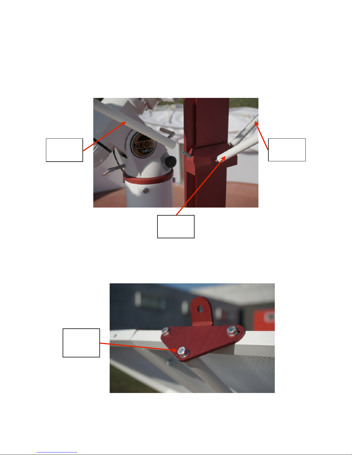
Now take the 3 rear tie rods (6): two are 1422mm long and one is 1453mm long. The longer rod must be screwed
into the threaded pin pointing in the opposite direction of the counterweights bar, just above the support device for
equatorial mounts. The two short rods instead should be placed laterally (one to the left and one to the right than
the first). To correctly insert the rod, place one end close to the corresponding plate (which we installed on the re-
flector) and the other end on the threaded screw of tie rods supporting block.
!
!
Then tighten until the end of the rod toward the plate pass within the plate itself. Take a M6x16 screw with washer
(27) and, by entering one for each plate, screw it on each of the 3 rods.
"
!
!
page !20
1422mm"
tie rod
1453mm"
tie rod
Securing screw
of tie rod on the
plate
1422mm"
tie rod

PrimaLuceLab iSrl Spider230 user manual
Now take the four support rods for feedhorn (5 - all of the same length, 1169mm) and, using for each a M6x16
screw with washer (27), secure them in front of parabolic antenna, one for each of the four plates. Tightening the
locking screw, 4 rods will remain in place.
!
!
!
!
Now loosen only the clutch knob of mount Declination axis and point the antenna towards the North. Consider that
the reflector will be forward biased (because you have not yet installed the second counterweight for Declination
axis) so be careful when you move it. Close the clutch to hold the reflector in place.
"
!
!
page !21
Insert a M6x16
screw with wa-
sher to close the
1169mm rod in
position

PrimaLuceLab iSrl Spider230 user manual
Take the second counterweight for Declination axis (4) and insert it into the support device for equatorial mounts,
as shown in the figure below. Place it towards the end of the plate, as for the other counterweight. So fix it by using
the two fixing screws and make sure it does not move.
!
Than take the safety catch and fix it at the end of the support device for equatorial mounts using two M6x12
screws.
!
!
!
!
!
"
!
!
page !22
Fixing screws of
Declination
counterweights
Safety catch

PrimaLuceLab iSrl Spider230 user manual
Now loosen the friction of Declination movement and rotate the antenna pointing toward the South horizon. Pay
attention to the distance between the reflector and the rear part of the mount. When the radio telescope is poin-
ting towards the South, the antenna must be close to the mount, but should not touch it.
!
If he touches it, bring back the radio telescope in "Home" position (ie with the antenna pointing to the North Pole
and the Right Ascension counterweights bar pointing downwards), unscrew the knobs that lock the support device"
for equatorial mounts on the mount head and slide it slightly upwards. Point on the South horizon again and check
that the antenna does not touch the mount.
!
!
"
!
!
page !23
The reflector has
not to hit the
mount
You can slide the Lo-
smandy bar to the cor-
rect position. "
Caution: When unscrew
the knobs, hold firmly
the antenna preventing
it from falling!

PrimaLuceLab iSrl Spider230 user manual
Take the feed horn support with LNB case (9), unscrew the 4 M5 silver screws and remove the case. Take the lower
part of the support and fix in front of the reflector on the feed horn support rods (5) with 4 M6x16 screws with wa-
sher (27 - one for each rod). Tighten the screws (without tighten too much) to fix the position of the support.
!
Now take the LNB with feed horn (12). Unscrew the disc from the feed horn, insert the feed horn into the just in-
stalled holder and screwed the disc again in front of the feed horn. Be careful not to drop the disc while screwing it,
it may fall on the reflector ruining it.
"
!
!
page !24
Feed horn"
support

PrimaLuceLab iSrl Spider230 user manual
Now take the RAL10PL receiver box t (20) and place it at the base of the pier. Take the white coaxial cable used to
connect the LNB to the receiver. Take the ends (that has to tighten to the LNB) and loosen the F connector.
!
Then insert the cable into the LNB box passing it to about 30 centimeters.
!
!
"
!
!
page !25
Coaxial cable
without F"
connector
LNB case
F connector

PrimaLuceLab iSrl Spider230 user manual
Then tighten again the F connector until the central part of the cable (the copper core called "hot head") is at the
height of the outside pin.
!
Screw the F-type connector plug on the top of the LNB (be careful that the central part of the coaxial cable, the
copper part, fits perfectly inside the center hole of the LNB connector, then screw the outer ring to secure all).
Then bring the box above the LNB and secure it by inserting to the side the 4 silver M5 screws that you had pre-
viously unscrewed, one for each hole the box has and that has to be set at the 4 tapped holes around the support
of the illuminator.
!
"
!
!
page !26
External pin "
of F connector
Hot head

PrimaLuceLab iSrl Spider230 user manual
"
Take 4 white cable ties and attach the coaxial cable by sliding it along one of the feed horn support rods (5), the one
parallel to the Right Ascension counterweights bar of the mount. With a pair of scissors you can cut the end part of
the band that sticks out. Warning: clamp the coaxial cable straight along the rod without kinks or loops.
!
"
!
!
page !27
M5 screws to set
the box on LNB
support
LNB box
Fix the coaxial cable
along the support rod
parallel to counter-
weights bar

PrimaLuceLab iSrl Spider230 user manual
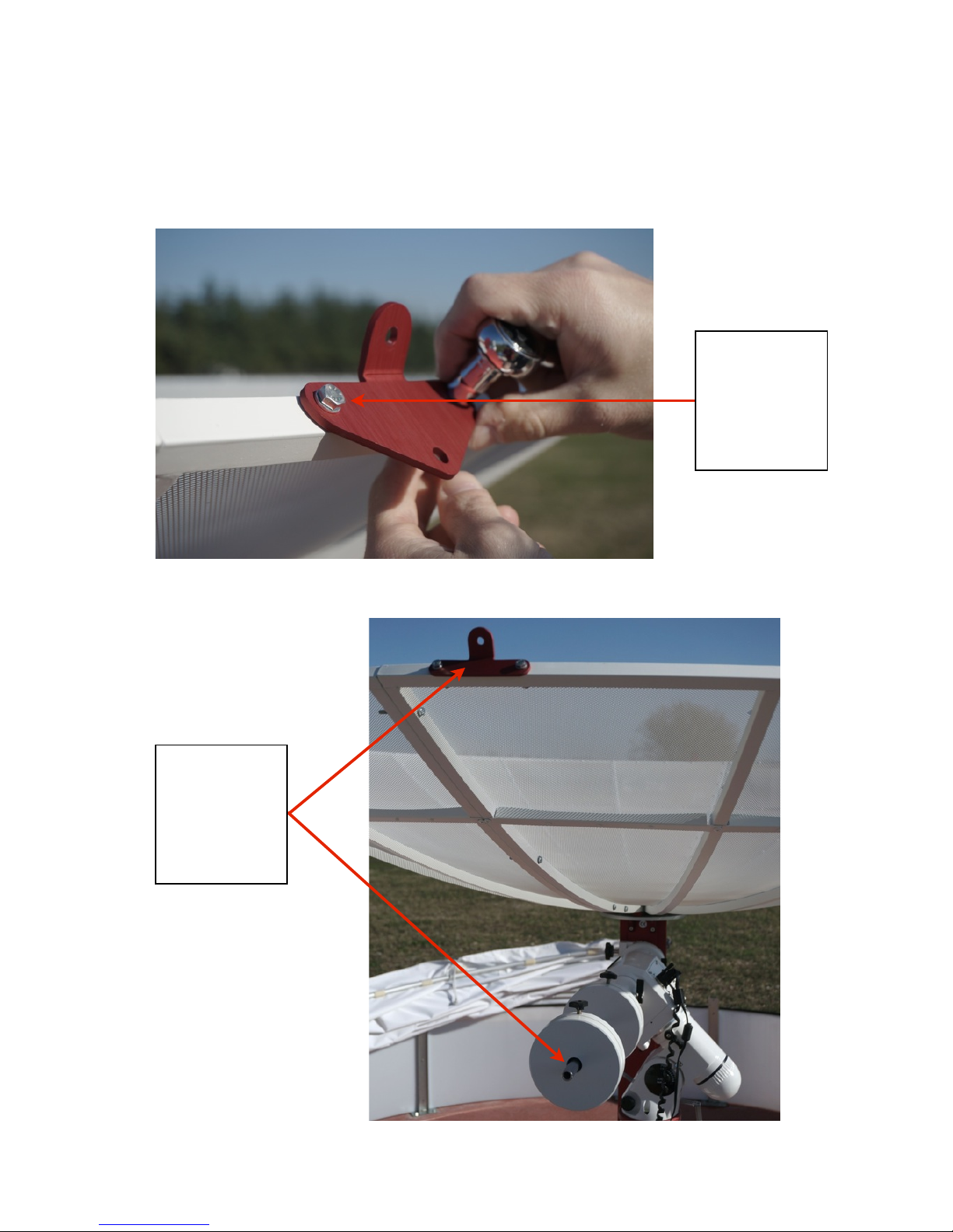
Now take the finder support (17) and place it at the end of the Right Ascension counterweights bar. Fix the support
to the bar with a safety M12x20 screw (25) and then tighten 3 the M6 grub screws placed laterally in the support.
The axis of the finder support must be more or less parallel to the plate of the sSupport device for equatorial
mounts.
!
!
!
!
(image of finder support without finder)
!
!
!
!
!
Then unscrew the 6 screws with blacks knobs all the way down, take the finder, insert it into the holder and close
the screws.
"
!
!
page !28
Finder support screws

PrimaLuceLab iSrl Spider230 user manual
Now take the RAL10PL pier support (21) and bring it close to the column.
You can attach it to the column using two clamps. This support allows you
to set the receiver box at the base of the column.
Now take the box containing the RAL10PL receiver, the control electronics
and power supply devices. You can secure it to the support using 4 M6x12
screws (29). Place the receiver box with cables passing facing the ground
as shown in this image. Then connect all the cables as shown in the photo
below.
You have now completed the installation of the radio telescope!
!
!
"
!
!
page !29
The gray cable is inserted below the
mount handpad
Power cable
Network cable for PC
connection
Coaxial cable for LNB
link
The angular black cable plugs into the
power jack of the mount

PrimaLuceLab iSrl Spider230 user manual
First use: mount polar alignment and finder alignment
!
Before you start to use the radio telescope it’s necessary to perform the mount polar alignment and check for per-
fect parallelism between finder installed on the mount counterweights shaft and the parabolic antenna. These two
procedures are necessary to be sure that the radio telescope points the correctly the area of the sky, when it is
controlled by RadioUniverse software.
!
!
Finder alignment on the Sun
This procedure should be performed during daytime with the Sun not covered by clouds. Even if you have not per-
fectly aligned the mount, having previously made a rough alignment is possible to align the finder. Take the mount
hand control and insert the connection cable in the plug below the hand pad and in the mount appropriate plug.
Now turn on the mount using the power button. The hand control will display a warning message on the damage
resulting from the direct observation of the Sun. Press the ENTER button of the hand pad to confirm that you have
read.
The LCD screen will display "Enter Location": press the numeric keys of the keypad to enter latitude and longitude
data of the radio telescope place of installation. You can use the vertical arrow keys to change the longitude east-
west and north-south latitude when the cursor flashes in the corresponding characters. Use the left and right ar-
row keys to move the cursor. Then press the ENTER key to confirm (press ESC key to go to previous step)
The screen will display the message "Set Time Zone": use the arrow keys to change the signs “+" and "-“ if needed.
“+" is used for East areas (Europe, Africa, Asia and Oceania), while the "-" indicates those in the West (North and
South America). Use the numeric keys to select the correct value (for example, Italy is +1). then press ENTER to
confirm or ESC to return to the previous step.
When the message "Date: mm/dd/yyyy", enter the date (note: in month/day/year format). Then press ENTER to
confirm or ESC to return to the previous step.
When the message "Enter Time", enter the local time in 24-hour format. Then press ENTER to display the time in
12-hour format. Then again ENTER to confirm or ESC to return to the previous step. When you see the words
"Daylight Saving?", Use the arrow keys to select "Yes" or “No". "Yes" indicates summertime and "No" indicates win-
tertime. Then press ENTER to confirm or ESC to return to the previous step.
"
!
!
page !30

PrimaLuceLab iSrl Spider230 user manual
The display will show "Polaris Position in P.Scope = HH: MM." This indicates the orientation of the Polar Star in the
field of polar scope. At this time, this is a parameter that we do not use, then press ENTER to confirm. Screen LCD
will show "Hour Angle of Polaris = HH: MM." Press ENTER to confirm again.
The display will show "Begin Alignment? 1) YES 2) NO": press the 2 button to skip the alignment procedure (it will
be performed later). The hand pad will display “Setup”. Now we need to activate the mount automatic tracking mo-
vement. In order to do so, press ENTER, and then press the button at the bottom right of the handpad (the one
with the up arrow) until the display shows "Tracking". Press ENTER to select and press the button again with the up
arrow until it says "Solar Rate". Press ENTER to select.
Now the mount will track the sun in its apparent motion in the sky. Take the Sun filter (19) and install it in front of
the finder and make sure it is fixed: before you put your eye to the finder eyepiece put, behind it, a hand with an
open palm to make sure that does not come too much light (if the filter does not work, it’s broken or is not comple-
tely mounted, light on your hand will be strong).
On the hand pad, press the “2” button: the display shows the
message “Tracking”. Click the 9 button to select the maximum
slewing speed and confirm with ENTER button. Now use the
Right Ascension and Declination movements of the mount (by
selecting one of the four arrow keys on the hand pad) to move
the radio telescope to point it roughly on the Sun. Watch the
shadow of the feed horn support projected on the antenna
disk. Using the mount motions, move the radio telescope until
the shadow appear perfectly in the antenna center.
!
!
Verified that the solar filter is working properly, bring the eye to the viewfinder, and check the position of the Sun.
You will see a disk (the Sun): if not at the center of the image, use the collimation screws (only the 3 in front 3 or 3
rear - you unscrew a screw and screw the other two) to bring it in the reticle center. Then tighten (not too much)
the collimation screws. The optical finder is now perfectly parallel to the radio telescope and then is ready for the
procedure for aligning the radio telescope to the sky.
If you want to turn off the mount, now you can loosen the Right Ascension and Declination clutches of the radio
telescope, point it on the Zenith (the antenna will point to the vertical) and close again the clutches. Press the
mount power button to turn it off.
"
!
!
page !31

PrimaLuceLab iSrl Spider230 user manual
Mount polar alignment
This procedure is performed during nighttime with sky clear from clouds (you need to see the North Star, for obser-
vers in the northern hemisphere or the South Pole for those in the Southern Hemisphere) and is to point the mount
polar axis to the celestial pole (the North Pole to the South Pole locations in the northern hemisphere and for those
in the Southern Hemisphere). The polar alignment procedure is described in the mount user manual but we see
here some helpful tips to make it quickly and accurately, as an example pointing the North Pole with the N-EQ6
SynScan mount supplied as standard with the Spider230 radio telescope (observers in the southern hemisphere
follow an almost equal procedure described in the mount user manual).
Turn on the mount using its power button. The hand control will display a warning message on the damage resul-
ting from the direct observation of the Sun. Press the ENTER button of hand pad to confirm that you have read.
Sullo schermo LCD comparirà la scritta "Enter Location": se non li avete precedentemente inseriti, premete i tasti
numerici della pulsantiera per inserire i dati di latitudine e longitudine del vostro luogo di installazione del radiotele-
scopio. Potete utilizzare i tasti freccia verticali per cambiare la longitudine est/ovest e latitudine nord/sud quando il
cursore lampeggi nei corrispondenti caratteri. Utilizzate i tasti freccia sinistra e destra per spostare il cursore. Pre-
mete quindi il tasto ENTER per confermare (premendo il tasto ESC tornate al passaggio precedente)
The LCD screen will display "Enter Location": if you have not previously entered it, press the numeric keys of the
keypad to enter latitude and longitude data of the radio telescope place of installation. You can use the vertical
arrow keys to change the longitude east-west and north-south latitude when the cursor flashes in the correspon-
ding characters. Use the left and right arrow keys to move the cursor. Then press the ENTER key to confirm (press
ESC key to go to previous step)
The screen will display the message "Set Time Zone": use the arrow keys to change the signs “+" and "-“ if needed.
“+" is used for East areas (Europe, Africa, Asia and Oceania), while the "-" indicates those in the West (North and
South America). Use the numeric keys to select the correct value (for example, Italy is +1). then press ENTER to
confirm or ESC to return to the previous step.
When the message "Date: mm/dd/yyyy", enter the date (note: in month/day/year format). Then press ENTER to
confirm or ESC to return to the previous step.
The display will show "Polaris Position in P.Scope = HH: MM." This indicates the orientation of the Polar Star in the
field of polar finder. You can imagine the great circle visible in the polar scope as a big clock with the hours 12:00
high. In order to make a good polar alignment, you have just to bring the North Star at the point of the great circle
corresponding to the time shown "HH: MM." So for example, if the value shown is 3:00, just bring the Polaris in the
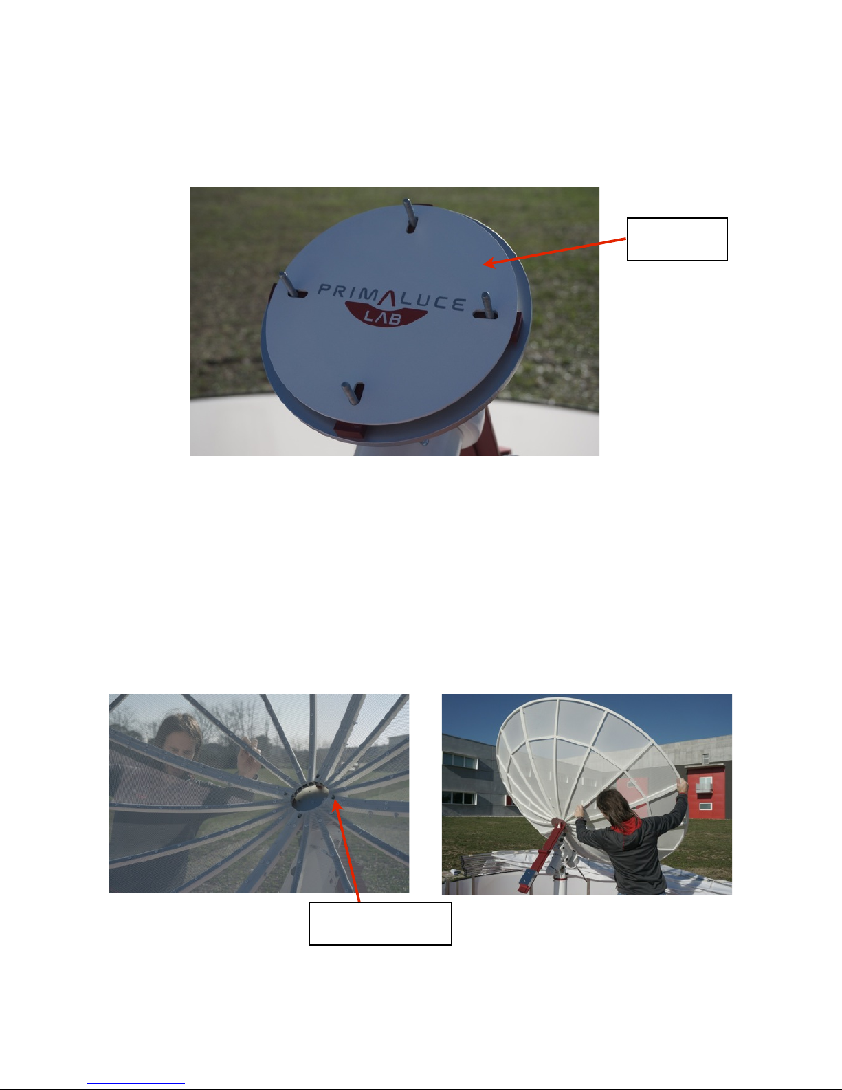
rightmost point of the great circle. Unscrew the cap white back of the mount and the smaller cap black front.
!
"
!
!
page !32

PrimaLuceLab iSrl Spider230 user manual
!
!
!
!
!
!
!
You will notice within a small scope parallel to the mount polar axis. Observe it from the front of the mount, in the
point where you have removed the little black cap. Open the declination axis clutch and rotate the radio telescope
antenna until you see the hole that allows the operation of the polar scope. Then close the clutch again to hold De-
clination axis of the radio telescope.
!
!
"
!
!
page !33
Rear cap
Front cap

PrimaLuceLab iSrl Spider230 user manual
Now approach the eye to the eyepiece of the polar scope: you'll have to kneel down under the antenna, be careful
not to bump the parabola or other mechanical parts of the radio telescope. The polar scope of N-EQ6 SynScan
mount has a focus wheel, the back of the polar scope itself, that you can set screwing or unscrewing.
!
!
!
!
!
!
!
!
You can see the picture below.
!
!
"
!
!
page !34
Point where to place
North Star if hand pad
sets hound angle of 3:00
Point where to place
North Star if hand pad
sets hound angle of 6:00
Approach the
eye to polar
finder

PrimaLuceLab iSrl Spider230 user manual
!
Then use the azimuth and height mount settings to correctly point the mount. Above we see two examples: If the
mount hand pad indicates "Polaris Position in P.Scope = 3:00" you have to place North Star in the far left of the
center circle. If it indicates "Polaris Position in P.Scope = 6:00“ you have to place North Star in the lowest point.
!
!
!
!
Adjusted the position of the North Star, close the polar scope (again with the two caps on the mount you removed
earlier - one white and one black). Take the control hand pad and press ENTER to confirm. The LCD screen will
show "Hour Angle of Polaris = HH: MM". Press ENTER to confirm and proceed to the next step or press ESC to re-
turn to the previous step.
Now the mount axis is perfectly aligned with the sky rotation axis and then is ready for the radio telescope align-
ment procedure on the sky.
!
!
!
"
!
!
page !35
Latitude knob
Azimuth knob
Latitude knob

PrimaLuceLab iSrl Spider230 user manual
!
First use: mount alignment
!
All computerized equatorial mounts, in order to allow the automatic pointing of antenna, will need to be aligned to
the stars in the sky. The alignment procedure must therefore be carried out at night and in good weather condi-
tions without clouds. It also depends on which mount is used (so you can refer to the manual of your mount), but in
general, the mount asks you to confirm the date, time, location (latitude and longitude of the place of observation).
Then it ask to point 1, 2 or 3 star alignment of your choice. You can follow these steps pointing at the stars in ali-
gnment with the finder as it was previously aligned with the radio telescope antenna.
!
We continue the alignment procedure recovering from the previous paragraph:
A) with the mount turned off, loosen the clutch of the Right Ascension and Declination motions and point the an-
tenna towards the North Star
!
!
!
(image of radio telescope pointed to the North Star)
!
!
B) Turn on the mount and set-up all initial data as described in previous paragraph. The display will show "Begin
Alignment? 1) YES 2) NO": press the 1 button to start the alignment procedure. You can then choose between
alignment with 1 star (1-Star Align.) 2 Stars (2-Star Align.) or 3 star (3-star align.).
!
C) The LCD display shows the message "Alignment" (Alignment) in the first line. Using the scroll arrows, select an
alignment method in the second line of the display, press ENTER to go to the next step or ESC not to do the
alignment.
!
"
!
!
page !36

PrimaLuceLab iSrl Spider230 user manual
D) Now the user must choose one or more alignment stars from a list provided by the control hand pad, and then
center the selected star adjusting the mount position. Choose one of the alignment mode. We suggest the 3-
star one, the other two modes are almost equal, but require fewer steps.
!
The display shows the message "Choose 1st Star " in the first line . Use the arrow keys to select the name of a star
in the sky that you know. Press ENTER and the mount will move trying to point this star. Note, do not position
yourself too close to the radio telescope as it moves quickly as the antenna, or the counterweights bar could hit
you. When the mount stops, you will hear a short tone (beep) and the display of control hand pad will shows the
message “Use dir. keys to center the object”. Check to see if the antenna is roughly pointed towards the reference
star and search it in the finder (check that it has not installed the solar filter otherwise you will not see anything! ).
Most likely the star will not be perfectly centered in the finder. You can use the arrow keys to move precisely the
mount until the star is perfectly in the center of finder reticle (the mount is set to the minimum speed of move-
ment, to increase it, click the RATE button and then a number: 1 is the minimum speed, 9 is the maximum, we re-
commend using the speed 6). Then press ENTER confirming that the finder (and therefore the radio telescope) is
pointing at the first alignment star .
If you have chosen the 1-star alignment mode, now the hand pad will display "Alignment Successful" and you will
press ENTER to complete the alignment. If you have chosen 2 or 3 star alignment will have to repeat the procedure
aiming other stars.
At this point, the mount is properly initialized and is ready to perform the automatic pointing and tracking of any
object in the Universe. It’s also ready to be connected to a computer for remote control via the supplied software
with the radio telescope. The computer must be equipped with the Windows platform (supported operating system
Vista, 7, 8 - 32/64 bit) and must have a Ethernet port.
!
!
"
!
!
page !37

PrimaLuceLab iSrl Spider230 user manual
First use: antenna setup
!
All the elements that make up the Spider230 radio telescope are pre-assembled and then ready for use after in-
stallation. However, to ensure you get the receiving system maximum performance, you need to check some de-
tails of the antenna. This procedure is performed with the radio telescope and the receiver turned off. First of all,
you need to verify that the distance between the feed horn disk and the center of the parabolic antenna is between
80 and 81cm. 80.5 cm is in fact the focal length of the parabola (230cm diameter multiplied by 0.35 focal ratio).
"
Then take the “Collimation rod” (16) and screw it on the feedhorn front thread.
"
!
!
page !38

PrimaLuceLab iSrl Spider230 user manual
In order to archive a greater precision, you can tighten the feedhorn front disc leaving a thicker thread. In this way
the collimation rod will be more precisely aligned with the feedhorn axis. Now look where the collimation rod tip: it
should be approximately in the center of the parabolic antenna.
If, as in the image above, it’s not pointing to the antenna, you can use the 3 120° Allen screws to adjust the tilt.
Unscrewing 2 screws and tightening the opposite one, the collimation rod tilt can be adjusted slightly (enough).
Caution: do not over-tighten these screws. When adjusting the angle of the collimation rod, make sure that the
distance between the feedhorn and the parabolic antenna, is always between 80 and 81cm.!
"
!
!
page !39

PrimaLuceLab iSrl Spider230 user manual
When the collimation rod is pointing to the center of the parabolic antenna, you can unscrew the collimation rod.
Be careful not to modify the position or the angle of the feedhorn by removing the rod collimation.
!
Then you will need to check that the feedhorn support with the LNB (9) is alignmed with the parabolic antenna. In
order to do this, you will need to activate the radio telescope and take a series of radio images of the Sun. This pro-
cedure will then be explained later in the manual, after you learn how to use the RadioUniverse control software to
properly record the data from the radio telescope.!
"
!
!
page !40

PrimaLuceLab iSrl Spider230 user manual
RAL10PL receiver
!
The RAL10PL receiver has been developed to work together with Spider230 radio telescope observing the most
intense radio sources in the sky at 11.2 GHz frequency. The receiver is composed of a sturdy plastic material con-
tainer (IP65, 300mm L x200mm W x 180mm H) which contains the thermo-stabilized receiver and power supply.
The instrument receives the RF signal from the LNB and the RS232 serial port from the system handling the an-
tenna: an Ethernet port provides communication with the instrument to the PC station. To optimize the stability of
the radiometer, the receiver is implemented within a PID loop that maintains a constant temperature electronics.
!
NOTE: RAL10PL receiver comes with all the connections ready for use. Before the first use, open the outer box
and check that all cables and connectors are fixed.
!
"
!
!
page !41
Serial port for control
of the mount
12V power supply for
the mount
Receiver power
Coaxial cable input for
LNB connection
Ethernet port for PC
communication
Power unit
Status LEDs of the
receiver

PrimaLuceLab iSrl Spider230 user manual
When power is on (green LED turns on) the receiver performs a calibration procedure and the initialization of the
operating parameters, during which the red LED flashes. After this stage, the red LED turns off and turns on the
YELLOW LED indicating the internal heater activity, if the ambient temperature has a value less than about 44°C.
When the internal temperature of the radiometer is stabilized (an event signaled by a flashing yellow LED), the in-
strument is ready for the observing session.
!
The operating parameters critical to the proper use of the receiver are as follows:
1) Post-detection amplification factors: gain of the receiver must be chosen in function of the intensity of radio-
source observed. For example, for the observation of the Sun just set a gain equal to 1 while for the Moon is re-
commended a gain of 4. For all other fainter objects (such as Cassiopeia A and Taurus A) is necessary to set the
gain to 10.
2) Offser parameter: it is necessary to position the reference value of the base line on a suitable point of the mea-
suring scale and it is between 0 and 50000. This is an indication that represents the signal used to "erase" the con-
tribution of instrumental noise, fixing an appropriate scale value for the basic radiometric line. “Base line” is defined
as the level of the output signal of reference, considered as a "zero" on the scale, relative to the situation in which
the antenna receives only the radiation of the "cold sky" in the absence of radio sources. This parameter does not
change the gain of the system and is set automatically whenever the user changes the gain of the receiver.
Both parameters can be modified using RadioUniverse control software, as we shall see in the following paragra-
phs.
Inside the receiver, there is a special electronic control unit that allows to control all components of the radio tele-
scope (including the mount) over a single Ethernet network cable. In order to allow for proper operation, before
installing and use RadioUniverse, you need to install the drivers and software to configure the Ethernet port of the
PC. The drivers for various operating systems (that emulate one or more COM ports) and installation instructions
are available for download at the website:
http://www.moxa.com/support/sarch_result.aspx?type=soft&prod_id=51&type_id=9
Choose your operating system (in the " Operating System" ) and download Nport Administration Suite. Turn on the
receiver (there’s not an on-off button, just connect the power plug ) and wait for the completion of the initial set-
ting of internal parameters (a few seconds after power up, you will hear a faint beep that confirms the start of the
receiver). Then connect the ethernet cable from the receiver RAL10PL to the Ethernet port of the PC and wait for
Windows to detect the limited or no connectivity. Unzip the file you downloaded ( in a folder of your choice) and run
the file Npadm_Setup_(version).exe file to launch the installation process. Follow the instructions on the screen, at
the end of the installation , leave the check mark on "Launch Nport Administrator" and press Finish to complete the
"
!
!
page !42

PrimaLuceLab iSrl Spider230 user manual
installation. Start the program by selecting the Windows Start button (bottom left of the screen), select "All Pro-
grams," then the folder "N-Port Administration " and finally "N-port Administration”. Once you start the program
you need to make an initial configuration. Select "Configuration" (1) in the right side menu and press the Search
button (2) to detect the device management of the COM ports .
!
WARNING: It 's very important to disable the firewall (if you have one installed in the operating system of the
control computer) as it prevents the scanning device.
!
In the window that opens select the device and then you can press the "Skip" to end the search. Now you need to
enable the device through the opening of the configuration web page. Then select the button "Web" (6), a page will
be opened by the default operating system browser. The device comes with default settings appropriate to the
proper functioning of the COM ports so no changes are required by the user in the web page so it can be closed
(click the X button to close your browser).
"
!
!
page !43

PrimaLuceLab iSrl Spider230 user manual
The device defines two serial ports (COM, each of them is connected to Spider230 mount and to RAL10PL receiver),
and for the proper control of the radio telescope, you need to define what are the numbers associated with them.
Click COM Mapping (7) in the left menu. Then select the "Add" button (8) to add ports, select the device (9) and
press OK (10). In case the device is not immediately visible, press the Rescan button.
!
!
!
!
!
!
The program then will map two COM ports and assign them
the name (COM1, COM2, etc ...). Select the "Apply" button
(12) to confirm the port mapping, then select OK to subse-
quent messages that will arise. The RadioUniverse software
will work with these two ports and then write down their
numbers.
Now the COM ports are enabled and ready for use, you can
close the program.
!
CAUTION: Whenever the ethernet cable is disconnected (or at each restart of the computer), you must repeat the
procedure ONLY in paragraphs 6 and 7, start the software Nport Administrator installed on your system to ena-
ble the connection to the device and the opening of COM ports. It is not necessary to re-map the COM ports, will
remain the same until the program is uninstalled.
Now we can start installing the software control and data capture of the Spider230 radio telescope: RadioUniverse.!
"
!
!
page !44

PrimaLuceLab iSrl Spider230 user manual
RadioUniverse control software installation
!
The radio telescope is equipped with RadioUniverse, the control software that allows you to control all components
of the radio telescope to record the radio waves coming from a specific direction in space and to obtain radio ima-
ges of the area of sky you want. To install the software, double-click on the installation file "RadioUniverseSetup.e-
xe" you will get a welcome window, click the "Next" button. In the second window you can select the installation
directory RadioUniverse. Base is C:\Program Files\RadioUniverse but if you want you can change this by clicking
the "Browse" button.
"
!
In the next window you can specify which name to set the link in the Start menu. To leave "RadioUniverse" click the
"Next" button. In the next window you can choose whether to create a shortcut on the desktop or an icon on the
task bar at the bottom of the screen. Click "Next" to continue.
"
!
!
page !45

PrimaLuceLab iSrl Spider230 user manual
"
In the next window summarizes all the information. Click the "Install" button to start the installation of RadioUni-
verse. At the end you will see a confirmation dialog box, deselect the option "Launch RadioUniverse" and click the
button "Finish" to finish the installation.
For proper control of the radio telescope is required ASCOM platform which can be downloaded from the website
http://ascom-standards.org/. Based on the computerized equatorial mount used by the radio telescope you have
also to download driver upgrade (different depending on the mount brand) from the page http://ascom-stan-
dards.org/Downloads/ScopeDrivers.htm. For example, if you use an N-EQ6 SynScan, you need to install the plat-
form and drivers “Celestron Unified”.
Before staring the software, switch on both the receiver and the mount, then connect the mount to your computer
where you installed the control software.
Then press the Windows Start button (bottom left of the screen), select "All Programs," then the folder "RadioUni-
verse" and finally “RadioUniverse". It will open a registration window, such as the one shown here.
To register RadioUniverse you need to send an email
toinfo@primalucelab.com indicating the serial number of the
instrument that you have purchased (ID code) and your email.
We will reply with a registration code that you can enter in the
field "Unlock Code". Pressing the "Register" button the software
will be recorded and you can use your computer to control the
radio telescope. Then click the button "Start application" to open
RadioUniverse."
RadioUniverse has all the necessary commands to control the
radio telescope and record radio waves coming from space.
"
!
!
page !46

PrimaLuceLab iSrl Spider230 user manual
!
"
!
!
"
!
Control software first use: settings!
To the left you will find the commands to enable communication
with the receiver and the mount and to customize the display win-
dow of the sky that appears on the center.
Before using the telescope you must tell the software the location
of your radio telescope with geographic coordinates LAT (latitude)
and LON (longitude). In the upper left, choose "Configuration" then
"Radio Telescope Location". This will open a window ("Radio Tele-
scope Location") in which you can enter the details of your place.
Note: You must enter the data with the correct positive or negative
sign. For the latitude, positive values indicate the northern hemi-
sphere and negative in the southern hemisphere. For longitude,
"
!
!
page !47
Window of"
measurements display
Radiometric datum gra-
ph function of time
Display options of the
radio map
Radio map of the"
Universe
Link commands to the
radio telescope
Results window

PrimaLuceLab iSrl Spider230 user manual
positive values indicate locations west of the Prime Meridian (Greenwich one), while negative values indicate loca-
tions east of it. For example, Pordenone (Italy) will have:
LAT: 45,992952
LON: -12,635844
If your computer is connected to internet, you can also use the Google Maps feature to enter the position. Type the
name of your city and press the button "Find". Locate on the map in the exact location of your radio telescope (Tip:
select the "Satellite" view) and double-click on the place where the instrument is installed. The coordinates will be
included automatically, on fields LAT and LON. Then click OK to confirm.
!
Now to connect the components of the radio telescope to your computer (make sure that all components of the
telescope are connected to the computer where you installed RadioUniverse). Go into the Windows Control Panel
and select "System" then "Device Manager" (name may change depending on the version of the operating system).
There’s a list of devices, double-click on "COM Ports" and note the COM port number associated with the receiver
and the mount. You can now close this window and return to RadioUniverse.
To activate the connection with the receiver, select the COM port from the
list in the top left, under the word "Serial Port Receiver” and press “Con-
nect” button. The data from the receiver will now be displayed by the con-
trol software.
"
To start the connection to the mount, click the "Connect" but-
ton in the Radio Antenna Mount, and a window will appear
"ASCOM Telescope Chooser". In the list, select the brand of
your mount (for N-EQ6, select "Celestron Scope Driver") and
then press the button "Properties".
This will open a new window ("Setup") in which you will need
to enter all the parameters of the equatorial mount:
"
!
!
page !48

PrimaLuceLab iSrl Spider230 user manual
1)Scope Type: mount type (for the N-EQ6 select
“Synta SkyWatcher Mount”)
2)Track Mode: for observers in the Northern Hemi-
sphere choose “EqN”
3)Serial Port: select the COM port relative to the
mount
4)Latitude:enter the latitude position of the radio
telescope
5) Longitude: the longitude position of the radio telescope
Confirm your choices by clicking OK and again OK button in the "ASCOM Telescope Chooser”. On the "RadioMap"
you will see a cross that indicates the location pointed to by the radio telescope.
Now you’re ready to record radio waves coming from space.
!
!
!
!
!
!
!
!
!
!
!
!
!
!
"
!
!
page !49

PrimaLuceLab iSrl Spider230 user manual
Advanced functions: record a transit
!
The one of transit is a technique that consists in identifying the object for which
you want to record the radio emission, pointing the radio telescope in the sky
where the object will be in the near future (eg 30 minutes later) and stop the
radio telescope in that position. Because of the apparent rotation of the sky
(caused by the rotation of the Earth), the object will move towards the area of
sky pointed by the antenna (a), there will be (b) and then pass (c).
!
To record a transit follow this procedure:
1) Defined as the object you want to record
2) Visualize it the sky map: if necessary, you can view additional data by checking the options on the left: Solar Sy-
stem, Stars, Horizon, EQ Grid
3) Using the mouse, move the arrow to the radio source that you want to resume transit, click with the right mouse
button and select “Sync Antenna”. The radio telescope will point to the requested area of the sky.
!
4) Select the tab "Transit" where you can set the parameters for recording your transit. If “Sequence" is selected in
the options window of RadioUniverse on the left, the Radio Map window shows a preview of the location of the
transit. You can set the following parameters:
a) Width of transition (°): length of transit in degrees
"
!
!
page !50

PrimaLuceLab iSrl Spider230 user manual
b) Offset of transition (°): size of the offset in degrees of transit, useful if you want to make a transit
asymmetric in which the object is not pointed at the center of the transit itself. If you want the object to
be studied in the center of transit, select the option below "Center"
c) Passes: number of consecutive transits recorded by the radio telescope
d) Dec Change (°): if the number of transits set is greater than 1, it is possible to indicate how many de-
grees to move a transit compared to another. With this option enabled, RadioUniverse show on the
"Radio Map" preview position (with a red line) of the different transits
e) Integration time (s): the number of seconds in which RadioUniverse performs an average of the signal.
Selectable values are from 1 to 30 seconds: the longer the lower the "noise" of data reading.
f) Auto Recalibrate: if you select this option RadioUniverse automatically calibrate the radiometric signal
taking it back, at the end of each transit, at mid-scale (with a value around 8000). This function is useful
when you want to take multiple consecutive transits of the same object (if it is necessary to record to
set high gain). In fact, due to the different height of the object with the capturing of different transits, it
is preferable to select this option to make sure that the radio value does not exit from the dynamic range value (from 0 to 16363).
5) Click the "Filename" button: in the window that opens, select the folder where you want to save the file and the
file name to be registered. For transits, RadioUniverse create a csv file that contains the radio data and the coor-
dinates of each recorded point.
6) Then click the button "Start Sequence" to start shooting the transit. The radio telescope will direct to the starting
point of transit and will stop there (the mount motors will be stopped).
!
7) While recording, you can see the values entered in the field "Sequence Result" and see the curve that results in
the top right.
"
!
!
page !51

PrimaLuceLab iSrl Spider230 user manual
!
8) At the end of the transit the radio telescope will move to the starting point again and will follow the sky move-
ment.
Suggestions :
1) When you want to record very faint objects (such as Cassiopeia A and Taurus A) it’s preferable to record more
consecutive transits then to average the obtained data (by reducing random noise). In order to do this, you can set
the "Passes" to a value greater than 1 (for example, if you select 3, the radio telescope will record 3 consecutive
transits) . Since transits are recorded at different heights from the ground, select the "Auto recalibrate" option in
this way RadioUniverse perform an automatic calibration between a transit and the other (bringing the radio value
around 8000, half of the receiver dynamic) .
2) In order to record faint objects, the transits technique of offers better results than the one of of radio-images
since during transits the radio telescope movement is stopped (so the noise coming from the atmosphere and from
the ground is constant), while during a radio-image it moves continuously (and therefore the contribution of the
noise varies and is difficult to quantify). In order locate a very weak object (such as Cassiopeia A and Taurus A) it is
thus possible to automatically record more transits moving the radio telescope in declination between transits. In
order to do this, select a number of transits greater than 1, then set the parameter "Dec Change (°) " to a value
greater than 0 (with the Spider230 radio telescope working at 11.2 GHz frequency that has a resolution capacity of
0.8 degrees, we recommend you to set 0.2 degrees). On the RadioMap window, ( if you have selected the “Sequen-
ce" option to the left) different red lines, corresponding to the different transits, will appear. Press "Start" to begin.
For example, you can record data from an 3 square degrees sky area (3 degrees by 3 degrees in RA and DEC) set-
ting a length of the transit of 3 degrees, 15 transits and a separation between the transits of 0.2 degrees. WAR-
NING: these recordings take a long time (the above example may take about 3 hours) so make sure that you have
enough time to avoid, for example, the mount meridian passage (which would rotate 180 degrees the mount chan-
ging a little the antenna position) .!
"
!
!
page !52

PrimaLuceLab iSrl Spider230 user manual
!
Advanced functions: record a radio-picture
!
To record a radio-image, the radio telescope moves continuously by scanning the desired area of the sky and recor-
ding, from time to time, the radio emission coming from each pixel that then compose the image. Some pixels can
record a radio waves number different from adjacent one and this amount is recorded by the radio telescope as a
number. Therefore, each number is associated with a color, a computer will substitute the numbers with colors
chosen by generating a radio image of the object. This technique is useful for recording radio images of intense
radio sources such as the Sun or the Moon, but also to quickly locate weak radio sources.
!
To record a radio-image, follow this procedure:
1) Define what object you want to record
2) Visualize it on the sky map, if necessary, you can view additional data checking options to the left: Solar System,
Stars, Horizon, EQ Grid
3) Using the mouse, move the arrow to the point you wish to record, click with the right mouse button and select
“Sync antenna”. The radio telescope will point to the request area of the sky.
4) In the "Antenna/Exposure Control” window select “Raster image”: here you can set the parameters for recording
of your image. If “Sequence" is activated in the options panel on the left, on Radio Map window you will find a
preview of the image position and size. You can set the following parameters:
a) Columns N°: number of columns that make up the image
b) Rows N°: number of lines that make up the image
c) Resolution (°): distance in degrees between each pixel of the image
d) Integr. Time (s): time in seconds in which the radio telescope is still on the same pixels
e) Exposures: number of images to be recorded
f) Moon correction: select this option if you want to record a radio image of the Moon. RadioUniverse will
correct the mount position, taking into account the Moon speed with respect to the sky background
(sidereal).
g) Sun correction: select this option if you want to record a radio image of the Sun. RadioUniverse will cor-
rect the mount position, taking into account the different Sun speed with respect to the sky background
(sidereal).
"
!
!
page !53

PrimaLuceLab iSrl Spider230 user manual
h) Correct DEC deviation: select this option to adjust the capture of pixels that generate the radio-image
based on the position in declination (we recommend that you always enable this option).
!
5) Click the button “Filename": in the window that opens, select the folder where you want to save the file and the
file name to be registered. For radio-images, RadioUniverse creates a FITS file that you can open and edit with
different astronomy software (also free such as FITS Liberator: http://www.spacetelescope.org/projects/fits_li-
berator/).
6) Then click the "Start Sequence"button to start recording the radio-picture.
The generation of the radio-image requires a variable time as a function of the acquisition parameters, but in gene-
ral, it is never short. You can see the image that is progressively generated both on the radio map and in the "An-
tenna/Exposure Control” panel.
You can change the way the picture is displayed (also while it is being created, not only at the end of the recording)
clicking the right mouse button on the image and select the option "Greyscale" or "Rainbow". For both it is possible
to select the "Streched" In this way, the software does not display the full histogram but will compress automati-
cally assigning black to the lowest value recorded and white the higher (in the case of “Greyscale”, different colors
in case “Rainbow”). It’s also available the "logaritmic" mode that serves to highlight the weakest details. To save
the acquired image, you can move the mouse pointer over the image in the "Antenna/Exposure Control” panel, click
with the right mouse button and choose "Save BMP".
!
"
!
!
page !54

PrimaLuceLab iSrl Spider230 user manual
In the area where the radio image is generated, you can find a with "On/Off Corr ." selector. This serves to indicate
the distance (in degrees) of the calibration point relative to the center of the radio image to be recorded. When you
use a radio telescope with a not stabilized LNB, the change in LNB operating temperature can strongly influence
the detected radiometric data.
In general, when the temperature increases, the radio value decrease. When the temperature decreases, the radio
value increases. For this reason, when you record radio images composed of many pixels (that require a long time
to execute) a way to minimize these variations is to use a calibration point outside the imaging area. This point is
only used to check whether, with a continuous series of measures, its value is constant or changes over time.
In order to use the calibration point, move the lever to the left or right of center: notice that on the RadioMap an
indicator of the calibration point position appears. The calibration point is set so that it lies at the same height from
the ground of the image to be captured center.
If you start the image recording (as explained above), you will notice that the telescope does not move directly from
one pixel to another, but it alternate a measure of each pixel to a measure on the calibration point. So an appropria-
te calculation displays the correct data reassembling the radio image .
In order not to use the calibration point , put the lever in the center of the indicator.
!
"
!
!
page !55

PrimaLuceLab iSrl Spider230 user manual
Advanced functions: performances optimization
!
Record radio waves coming from space with a non-professional instrument is a complicated operation, in fact,
apart from the Sun and Moon that are two intense radio sources, all other objects (such as Cassiopeia A and Taurus
A) are very weak and have an emission just higher than the background noise of the Spider230 radio telescope. For
this reason, optimization and proper use of the entire system receiver (antenna and receiver) is essential.
We report here a series of observations and recommendations that help improve the performance of Spider230:
1) Antenna optimization: on page 38 of this manual we described how to perform a preliminary adjustment of the
antenna (focus point and feedhorn axis). Now let's see how to adjust the system even better. For a greater antenna
efficiency, it is necessary that the feedhorn axis is corresponding to the one of the parabolic antenna. In order to
fine-tune this, we use the technique of recording radio images of the Sun.
Having off the Spider230, install the solar attenuator on the receiver. Then turn on the receiver and the mount:
connect your control computer, start the RadioUniverse software and connect to the radio telescope. Point to the
Sun and record a radio image of the Sun itself, with a good resolution (for example, you can shoot 10 x 10 pixels
with a 0.1 degrees resolution). Look at the picture on the Radio-Map area of RadioUniverse: move the mouse ar-
row on the point where the radio-map maximum is, click with the right mouse button and select "Sync Antenna".
The radio telescope will point to the real center of the Sun (which might be slightly shifted with respect to the
theoretical position reported by RadioUniverse).
"
!
!
page !56

PrimaLuceLab iSrl Spider230 user manual
Now observe the parabolic antenna of the radio telescope and, in particular, the feedhorn shadow relative to the
center of the disc. If, as in the image above, it is not perfectly centered (in the picture is slightly shifted towards the
bottom), you need to make an adjustment of the position of the illuminator support moving it in the opposite direc-
tion to the one where the shadow is shifted (in this case then it is necessary to move the illuminator upwards).
!
!
You can do this by slightly moving the 3 or 4 holes plates support (7 and
8). Slightly unscrew the 2 screws that secure each plate on the body of
the parabolic antenna and move the plate itself towards the front or the
rear of the parabolic antenna. You can only make a small adjustment
(plates have a slot that allows you to adjust the position of about 1 mm)
but it will suffice for this purpose. Adjust the position of the plates, and
then secure them by tightening the screws again.
!
!
!
Now recorded a new radio image of the Sun and point, as before, the point of maximum emission. When you will
find that (like the picture below) the shadow falls in the center of the parabolic antenna, you'll have perfectly adju-
sted the feedhorn position.
"
!
!
page !57

PrimaLuceLab iSrl Spider230 user manual
2) Receiver optimization: because of the needed high gains, especially for the recording objects outside of Solar Sy-
stem, it is absolutely critical to capture data at a constant working temperature. in order to do this, the RAL10PL
receiver has an internal heater with an electronic stabilization system that brings the receiver temperature at 44°C
and maintain it with 0.1°C accuracy. Therefore we recommend to pay attention to the constancy of the temperatu-
re (which can be read in the top left part of RadioUniverse, close to the value of radio emission). In fact a not con-
trolled variation of temperature will cause a change in the value recorded radio that can be confused with a real
radio emission.
For proper operation of the RAL10PL heater, it is recommended that the ambient temperature does not exceed
35°C. If, during the hot summer days, the direct light of the sun warms the receiver box to very high values and the
temperature reading is above 44°C, it is advisable to open the receiver box to allow air to cool it slightly. You can
also place, on top of the receiver, an object large enough to keep the receiver under shadow. If not enough, you can
place a fan that constantly blows air inside the RAL10PL box. Then wait for the temperature to stabilize at 44°C to
start the recordings.
The graph below was recorded by keeping Spider230 pointed towards the North Star (thus always to the same
point in the sky that does not have radio sources recordable from the radio telescope) for 8 hours. The recording
was made under optimum atmospheric conditions, without any cloud in all the recording period. The blue line sho-
ws the variation of the signal recorded as a function of the working temperature of the receiver (red line) and the
one of the environment (green line).
"
!
!
page !58

PrimaLuceLab iSrl Spider230 user manual
It’s possible to note how the receiver temperature affects in an important way the recorded data (when the tempe-
rature of the receiver increases, the recorded value decreases and vice versa). It’s important to note that even the
ambient temperature influences the recorded data: in fact, during the night (the central part of the graph) in which
the receiver's temperature is stable at 44°C, the value of the radio increases slightly due to the decrease of the
environmental temperature. This phenomenon is evident when the LNB is not equipped with a thermal stabiliza-
tion system.
So when you want to record from very faint objects, you need to pay attention to changes of ambient temperature.
In particular, it is not advisable to record during sunrise or sunset, when the ambient temperature changes signifi-
cantly.
!
3) Tips for radio images: based on the receiving system settings (described on page 41, setting the required gain as
a function of the object to be recorded), when we point the radio telescope to an area of the sky free of radio sour-
ces, we obtain a numerical value (that, for example, can be of about 8000). When you move the radio telescope
toward a radio source, the value increases due to the signal that arrives from the source itself. Because of the wea-
kness of the signals typical of radio astronomy, it is essential that the background noise remains as constant as
possible. The factors that lead to the variation of the background noise are temperature variations described in the
previous paragraph and variations of the antenna pointing positions. If we set a high gain (eg 10), point the antenna
to the vertical and then move progressively towards the horizon, we can see that at the radio value tends to de-
crease and then increase again.
This phenomenon is due by two main causes. The first is the atmospheric noise which is low when pointing the tele-
scope toward the vertical and progressively increases as it moves toward the horizon (because the instrument
"look at" a greater thickness of the atmosphere). The second cause is the spillover effect. In practice, due to the par-
ticular geometry of the antenna, the feedhorn “look at” an greater area than the one of parabolic antenna disk. This
means that when the point the antenna to the zenith (vertical position), the feedhorn "look at" radio signal emitted
by the ground and for this reason the radio signal increase (instead of decrease).
The added effect of these two phenomena leads to variation of the signal simply when the antenna of the radio
telescope moves from one point to another one of the sky. Since the direct recording of radio images with the "Ra-
ster Image" feature of RadioUniverse needs to move the antenna to reconstruct the image, this method is good for
intense sources such as the Sun and the Moon but it is not the useful for weak sources (where having a constant
background noise is crucial). For these objects is therefore better to use the transit technique, described on page 51
and then reconstruct the image using the RUviz software (described in the next chapter).
!
"
!
!
page !59

PrimaLuceLab iSrl Spider230 user manual
Advanced functions: create a radio-map with RUviz
!
When you want to record the faint radio waves coming from radio sources outside of the Solar System, the data
processing is critical. That's why we designed RUviz software (RadioUniverseVisualizer) which allows you to import
data captured by RadioUniverse and process them in a very simple and fast way. In this way it is possible, starting
from the registration of several consecutive transits of the sky area that you want to analyze, to create radio maps
of faint radio sources such as Cassiopeia A and Taurus A. In order to start the software, double-click on “RUVIZ.exe”
file (no need for installation). A window will appear, like the one shown here.
!
RUviz uses special algorithms in order to to reduce the signal drift caused by the change of the antenna pointing.
Other features allow you to minimize the drifts due to variations in ambient temperature. Select “File” then “Open
File”: A window will open where you can select the file RUD format (RadioUniverse Data) to process.
RUviz will open the file and will display its data:
-
at the top left you can see the real radio map with the coordinates of Right Ascension and Declination
-
in the lower left you have the map of the sky with radio sources, if present, indicated in yellow
-
in the lower right you have one of the transits that are part of the radio-map
-
on the left you have the display and saving options
!
"
!
!
page !60

PrimaLuceLab iSrl Spider230 user manual
Selecting the option “Show Title and Subtitle” you can make it appear, in the upper right corner, spaces in which, for
example, you can add the names and characteristics of the radio-map.
The raw data are displayed in “RAW DATA”. Below this area, there are various RUviz options:
-
Automated offset: each radio-map is composed of several transits that are taken at different times, and at diffe-
rent heights from the horizon. For this reason, between a transit and the other, the radiometric signal changes
only for the variation of atmospheric and ground noise. This function automatically calculates how these values
change between one and the other transit and corrects this variation.
-
Regression Offset: within a single transit, the variation of the working temperature of the receiving device (eg the
one of LNB) can lead to a progressive increase or decrease of the values. This option automatically normalizes
these drifts.
-
Resample RA: set the image Right Ascension resolution to the same values of Declination (it depends on how you
set the data captured in RadioUniverse).
-
Show DEC Grid: shows the lines in Declination corresponding to the tracks of different transit.
-
Show Visual: shows the star map.
-
Show 2D Graph: shows graph with the values of one of the transits (to change the displayed transit, just click with
the right button of the mouse on the desired part of radio-map).
-
Show Beam Width: shows the size of the antenna beam (relative to Spider230 with 11,2 GHz receiver).
"
!
!
page !61

PrimaLuceLab iSrl Spider230 user manual
At the bottom left you will find the 3D visualization of the processed data. You can change the display using the left
mouse button and moving the mouse cursor itself.
If, for any reason (such as the momentary passage of a cloud), one of transits was "ruined" and shows strange va-
lues while the others have been successfully registered, you can remove only this transit. In order to do so, you can
move the mouse cursor over the radio map corresponding to transit to delete and click with the right mouse but-
ton.
You can now save the data in graphic form (image) by pressing the button “Save Report” or in CSV format (for ex-
ternal processing with other programs) by clicking the button “Save Data as CSV”.
!
!
!
!
!
!
!
!
"
!
!
page !62

PrimaLuceLab iSrl Spider230 user manual
Experiments: the Sun, radio waves source
!
Our star emits not only visible light but also other frequencies in the electromagnetic spectrum. Everyone recogni-
zes the solar heat on our skin, expression of infrared radiation. But the Sun also emits radio waves and it’s also the
strongest radio source in the sky.
The Sun emits radio waves for both thermal mechanisms (due to its high temperature) and for non-thermal (for
example synchrotron radiation when the electrons are forced in a spiral motion around magnetic field lines). For
wavelengths greater than 1 cm (ie less than about 30 GHz), the emission of radio waves from the Sun is composed
of two components: a constant one called “Quiet Sun” due to the heat of our star and a variable one called “Distur-
bed Sun” that varies over time and depends on the presence of sunspots or flares.
Spider230 lets you check that the Sun emits radio waves. With the radio telescope turned off, install the solar atte-
nuator (necessary because instrument high sensitivity would resolute in signal saturation if you point our star wi-
thout a "filter"). Then turn on the radio telescope and, after performing the initial steps of starting and connecting
to the control computer with the RadioUniverse software (as described on page 47), wait for the receiver to reach
thermal equilibrium. We now use the "Raster image" feature to record a low-resolution radio image of the sky
around the position of the Sun, and then to center it precisely. In the "RAL10 Control" area on the right, select a low
gain, 2 or 3 is fine. Then move your mouse to the position of the Sun indicated in the "Radio Map" of RadioUniverse.
"
!
!
page !63

PrimaLuceLab iSrl Spider230 user manual
Click with the right mouse button and select "Sync Antenna". Spider230 will point to the required sky area. Then
select the "Raster Image"tab and set a fast record at low resolution, for example 5 columns, 5 rows, resolution
0,5° and an integration time of 1 second. Choose the option "Sun Correction" and click the "Start" button. As soon
as the radio telescope will end the record, look at the position of the illuminated pixels: probably the position of the
Sun will be slightly shifted respect to the center, then click the illuminated pixels in the "Radio Map" with the right
mouse button and select "Sync Antenna". You will notice that in the top left, in RadioUniverse window, the radio
value "Received" will change from very low (close to 0) to about 8000. You perfectly pointed the antenna on the
Sun and you're recording in real time its radio emission.
Now let’s take a radio image of the Sun with a higher resolution in order to precisely verify it’s emission. For exam-
ple, we can set 20 columns, 20 rows, resolution 0.1° and an integration time of 1 second. Click the "Filename" but-
ton to select the name and the folder of the file to save. So, after checking that the "Sun Correction” option is al-
ways selected, press the "Start" button to start the record. At the end, as displayed in the image below, you will get
a radio image of the radio emission of the Sun.
"
After this high resolution image recording, point the radio telescope perfectly in the center of the Sun: now you can
proceed with the continuous monitoring of its radio emission for a long time. Select the "Monitoring" tab and in the
"Duration of measurement (h:m)" field enter the recording time (eg 1 hour). Select the "Sun" (for tracking rate cor-
rection). On the left side of the RadioUniverse window select the "Log received data to file" (allows you to record
the data in a TXT file with a time reference). Then click the "Start" button to begin recording.
"
!
!
page !64

PrimaLuceLab iSrl Spider230 user manual
At the end of the recording, uncheck the option "Log received data to file", then go to the directory where you in-
stalled RadioUniverse. Here you will find a file called log_(date)_(time).txt that contains the saved data, we now
learn how to process it with software like Excel (or similar). After you open Excel, select "Data" then "Load External
Data" and then "Import Text File". Select the file you saved before and click the button “Data".
"
!
!
page !65

PrimaLuceLab iSrl Spider230 user manual
In the window that opens, select "Delimited" and press the button "Next". In the next window, select only the op-
tion "Semicolon" and press the “Next" button. So you end the import procedure clicking “Finish". A window will
open, confirm by clicking "OK." So you will get a file with three columns: the first shows the time (in Julian format),
in the second the radio signal, in the third temperature (multiplied by 10). Insert a blank line above the data (click
with the right mouse button on the number 1 to the left of the first value in the first column and select "Insert"),
then enter the names of TIME, SIGNAL and TEMPERATURE.
!
Now we need to convert the time in the right format. Please add a blank column to the right of the first column
(click with the right mouse button on the letter B above SIGNAL and select "Insert"). Then select the second row of
the second column and write
=A2-2415018,5
Confirm pressing the keyboard ENTER key. Then apply this calcula-
tion to all the cells of the column. In order to do this, click on the blue
square that appears at the bottom right of the just calculated cell and
holding down the mouse button, move the cursor down until you
reach the last row. In this way, the calculation will be extended to all
the other cells.
"
!
!
page !66

PrimaLuceLab iSrl Spider230 user manual
Now, keeping the selection on all the just calculated cells, place the mouse cursor over one of them, press the
mouse right button and select “Cell Format". Select "Time" and confirm with "OK". Cells now show the time in the
UT (Universal Time) format. You can now write also the header of this column as TIME.
Now select "Insert" then "Chart" then "Line" and then
"Lines". You will see a blank area of the chart, click on it
with the right mouse button and select "Select Data". In
the window that opens, click the "Add" button to add a
new data series. Then press the button to the right of the
“Name” field (indicated by the red arrow in the photo on
the left), the window will become smaller, click on cell C3
(where it is written SIGNAL) and press enter to confirm.
!
Repeat the same step for the field "Y Values" where you
have to select all the cells in the third column that contains the radio detected values and the "Category Axis Labels
(X)" where you select all the values of the cells of the second column contains the recording time. Finally confirm all
pressing the "OK" button. You can expand the graph area to better view the data.
"
!
!
page !67

PrimaLuceLab iSrl Spider230 user manual
Now you have a set of data that you can easily compare with data recorded even by professional radio telescopes.
Some sources available on the Internet:
-
Nobeyama Radio Observatory: http://www.nro.nao.ac.jp/en/
-
Australian Government - Radio and Space Weather Services - Learmonth Observatory: http://www.ips.gov.au/
Solar/3/4
-
Ottawa 10.7cm radio flux: http://www.spaceweather.gc.ca/solarflux/sx-eng.php
"
!
!
page !68
 Loading...