

Page 1

INSTRUCTION MANUAL
1/5 SCALE RAMINATOR MONSTER TRUCK
WWW.PRIMALRC.COM
Page 2

Table of Contents
1
Safety Guidelines
Terms of Use
Safety is Your Responsibility
Gas Engine Use Warning
Assembly Instructions
Wiring Diagram
Remote Engine Killswitch & Fail-Safe
Radio Details
Before You Drive
Running Your Truck
After you Drive
Choke Removal Instructions
Steering Servo Saver Adjustments
Brake Adjustments
Transmission Gears Adjustment
Troubleshooting Guide
Assembly
Differential
Front Axle
Rear Axle
Transmission
Engine
Chassis
Fuel Tank
Receiver Box
Main Sway Bar
Linkage
Axle
Shock
Sway Bar Link
Tire
Roll Cage
Body
Parts List
Pg.
01
01
02
02
03
04
04
05
06
07
07
08
08
09
10
11-12
13
14-18
19-21
21-25
25-27
28-32
33
34-36
36
37
38
39-41
41-43
43-44
44-49
50-51
52
Thank you for purchasing the Primal RC 1/5 Scale Monster Truck.
This manual contains the instructions you need to operate and
maintain your truck. It is very important that you take the time to read
and understand the instructions and radio manual. Make sure you read
and follow the precautions and warnings in the Safety Guidelines
section. These guidelines will educate you on how to run your truck
safely and maximize its longevity and performance.
This truck requires advanced R/C user experience and expertise. You
must be 18 years of age or older to operate this vehicle. Even if you
are an experienced R/C driver, it is important to read and follow the
safety guidelines in this manual.
If you have any questions regarding this vehicle or this manual: Stop.
Do not use this vehicle and contact us at [email protected].
Thank you again for your purchase and we look forward to exceeding
your expectations.
Safety Guidelines
WARNING – RISK OF FIRE, INJURY OR DEATH
The truck is not a toy. The truck requires an advanced set of skills and is not
intended for use by children or minors under the age of 18. The truck is
intended to be purchased and operated by competent, adult R/C users
possessing qualified skills and experienced driving ability. The user of this
vehicle should be practical, mature, intelligent and display good common
sense.
Caution must be taken to ensure the safety of yourself and others around you.
This truck is very large and is capable of high speed and quick acceleration.
Collisions of a critical nature (injury, death, severe property damage) can
result if the truck is operated in a careless or unsafe manner. Always take
great care to make sure all systems are working properly before operating.
The user must be aware of their limits and abilities. Make certain to have
adequate space where the truck can be run safely.
Instruction Videos Available at
The truck requires the use of 2-stroke gasoline for its engine. Gas engines
and 2-stroke gasoline have a very high risk of fire and injury if they are
PrimalRC.com/Video/TruckInstructions
handled improperly. The truck comes equipped with a NI-MH receiver battery.
Please read and understand the proper procedures for charging the battery.
The user must read and understand all the included instructions regarding the
proper operation, maintenance and safety precautions in using a 2-cycle gas
engine and charging batteries.
Terms of Use
This product is sold by Primal RC with the understanding that the buyer accepts full responsibility for all actions associated with its use. Serious injury,
property damage, or death can result from driving the monster truck or using any of the included accessories in an unsafe or irresponsible way. The
buyer assumes all liability with this product including any actions that occur due to a failure to follow its safety and operating instructions resulting in
unsafe or improper use or any action that violates the pertinent laws and regulations. Primal RC, and all the Primal RC dealers, will not be held
accountable under any circumstances with the use of this product resulting in property damage, personal injury, or death. This includes any willful or
unintentional damages that may arise out of the assembly or use of the product or its accessories. The user accepts all liability by the act of using and
operating the truck and releases Primal RC, and all Primal RC dealers of any and all liability associated with its use. Primal RC requests that you do not
use this product if you as a user do not accept liability of ownership. If you don’t accept liability, please do not open any of the enclosed accessories, do
not attempt to start it, and contact us to make arrangements to return the product. Used vehicles cannot be accepted for returns or exchanges under
any circumstances. The material included in this manual can be changed without notice. Primal RC reserves the right to make improvements to the
products with no commitment to integrate those improvements into products sold previously. The manual is subject to change at the discretion of Primal
RC. For the latest version of the manual please visit www.PrimalRC.com.
If you have any questions regarding this Terms of Use, stop and do not go any further. Do not run your vehicle and contact Primal RC at
[email protected].
1/5th RAMINATOR MONSTER TRU CK
Page 3

Safety is Your Responsibility
2
Your radio system may be subject to radio interference from many sources that are out of your control. Please be aware that
•
radio interference may cause a temporary loss of control. Allow adequate space in all directions when running your truck to
prevent collisions if radio interference should occur.
Test the range of your transmitter in the area you are driving. Make sure not to drive too far and go out of range.
•
After testing the range, start by driving slowly in the area to make sure there is no interference that can cause temporary losses
•
of control.
Always test the failsafe system every time before use to ensure it’s working properly (instructions are in the radio manual).
•
Use new or freshly charged batteries in order to boost signal output power and range.
•
The motor and exhaust become hot during use. Be careful not to touch them while hot to avoid getting burned.
•
Drive in the proper area. This product is not designed to be used in heavy traffic areas where its operation would cause
•
pedestrian and vehicle interruptions. This is recommended to prevent collisions causing property damage, injury, or death.
Try to always bring a friend while driving. Another set of eyes is helpful to identify potential hazards such as an animal or person
•
crossing in the driving path.
Always have a clear view of the model when driving. Do not drive at night or when your vision may be blocked in any way.
•
Don’t drive the model too close to you, other persons, or property where collisions may occur. Allow a comfortable amount of
•
space to maneuver the truck.
Be sure to check over the truck after each driving session. Check for damage or any loose parts and correct any issues right
•
away before using again. Make sure to check and tighten the wheel nuts before each session.
Do not pick up the truck by its wheels or tires. Keep your hands free and clear of any moving parts when the electronics are
•
turned on. Gravel, dirt, sticks, and other debris can be kicked up from the rear wheels during aggressive starts. Avoid standing
directly behind the truck and make sure other watchers are at a safe distance to avoid being hit. Eye protection is always
recommended.
Avoid making changes not shown or suggested in the instruction manual. You can cause damage to the model and injury to
•
yourself or others if the product is altered in a way not intended.
Remember: SAFETY FIRST. Create a safe environment to run the truck and use good common sense. This will ensure
•
maximal enjoyment while using the truck.
Gas Engine Use Warning
A mixture of gasoline and 2-stroke oil is used for fuel. Please use caution when handling fuel.
•
Keep fuel away from open flames, heating sources, direct sunlight, smoke, batteries or any ignition source. Store fuel in a well-ventilated area.
•
Store fuel and truck in a location children can’t access.
•
Keep fuel and truck away from children.
•
Gasoline is flammable, toxic, and can produce noxious vapors. The exhaust emitted from the truck can also produce noxious vapors. These
•
vapors can irritate eyes, respiration, and be dangerous to your health. Always operate the truck in a well-ventilated area.
The 2-cycle engine that comes on this truck only uses a mix of gasoline and 2-stroke oil. The oil/gas mix is how the engine is lubricated. Never
•
run straight gas through the engine as catastrophic damage may result. Never use glow fuels intended for R/C car use.
WARNING – FIRE RISK: EMPTY THE FUEL TANK BEFORE STORING THE TRUCK.
1/5th RAMINATOR MONSTER TRU CK
Page 4

Assembly Instructions
3
This truck is shipped in two boxes. One box contains the main chassis with body installed, 3 sticker sheets, two wheels,
transmitter, battery, charger and accessories. The second box contains front and rear axle, brake system, two wheels and four
shocks.
Before assembling and starting your truck, read and understand all manuals and familiarize yourself with the truck completely.
If you decide this truck is not the right choice for your or you do not want to assume responsibility for your safety, then do not
attempt to assemble or start it. Do not run the vehicle at all and please contact us to make arrangements to return the vehicle.
If your vehicle arrives with damage from transit please do not run the vehicle, and contract us instead. Used vehicles cannot be
accepted for returns or exchanges under any circumstances. If you have any questions about your truck, please email us at
[email protected]. Maintenance and replacement parts may be purchased directly from www.PrimalRC.com.
If you are prepared to assemble the truck, visit our website and view the installation videos.
See instruction video on www.PrimalRC.com/Video/TruckInstructions
Then follow along the instructions provided below. If you do not feel comfortable completing the assembly below. STOP. Do not
use the truck. Contact us and we can discuss the concerns with you on the phone or by email.
This truck is intended for users that have extensive experience with gas R/C vehicles and 2-Stroke engines.
1. Position main frame and axles on a surface with enough clearance for assembly.
2. Install the brake rotor on the driveshaft and install the drive shaft pin through the drive shaft and pinion gear shaft.
3. Slide the drive shaft from the axle into the drive shaft coming out of the transmission. Make sure the brake rotor is installed on
the axle.
4. Attach the axle to the four links already assembled on the main chassis.
5. Install shocks on the main chassis and axles. Note: hardware is already installed on axles and chassis.
6. Connect the two servo wires to the wires coming out of the receiver box. There is no preference for left or right servos –either
servo can go into either plug.
7. Attach top sway bar links to already installed sway bar on the chassis. Then attach lower sway bar links to the axle.
8. Install the brake calipers with one pad on each side of rotor (see diagram assembly instructions #66).
Note: The two bolts that hold the brake pads to the caliper should be installed using RED lock tight at the right position.
Without lock tight, these screws will come undone very easily.
10. Install the brake cables (see diagram assembly instructions #66). Make sure to route cables as smoothly as possible for
ease of operation. Cables should not be bent sharply. Zip-tie cable in strategic location to avoid snagging during operation.
Ensure suspension can travel smoothly without pulling on brake cable. See instruction video on www.primalrc.com/video/
TruckInstructions.
11. Initial brake cable adjustment: First, ensure your throttle servo is working properly and giving full throttle to carburetor. Then
in neutral (i.e. your throttle is not being applied) slide the brake cables into the brake servo cable splitter. Adjust the stop collars
so that the breaks are about to apply as soon as you trigger the transmitter to brake position. This adjustment is something that
you will fine tune to your needs. Front and rear bias can also be adjusted at the same time.
See instruction video on www.PrimalRC.com/Video/TruckInstructions.
12. Install wheels using supplied lug wrench. The hex nuts have a serrated side, ensure it is facing the rim.
13. Remove protective body film, then install stickers on the body.
See instruction video on www.PrimalRC.com/Video/TruckInstructions.
14. Charge the battery with included charger.
15. Install batteries into transmitter.
16. Follow the instructions in the “Before You Drive”, “Running Your Truck” and “After You Drive” sections of this manual.
Note: Looking at the pictures of the truck on our website can guide you to ensure that you are assembling the truck correctly. Also
viewing the instruction videos will give you tips on how to install everything correctly and easily.
1/5th RAMINATOR MONSTER TRU CK
Page 5
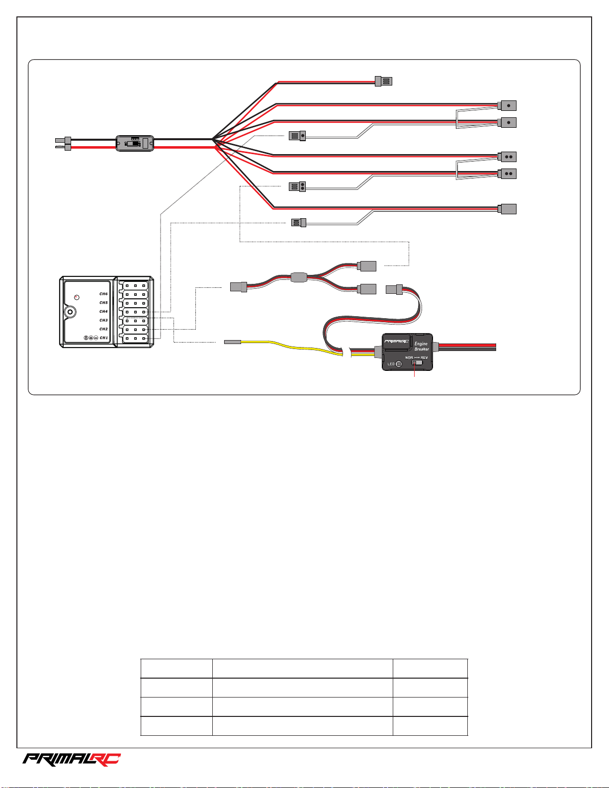
Wiring Diagram
4
To battery
T plu g
Bin d/ VC C
Swi tch
CH2
When using extra battery for the receiver,
pull out the positive pin (Red).
To receiv er B ATT.
_
CH1
CH4
_
+
S
+
S
_
+
S
_
+
S
Y-link
To receiv er C H1
To Y-link
To receiv er C H4
S
+
VCC
-
_
+
Ste ering ser vo 1
S
_
CH1
+
Ste ering ser vo 2
S
_
+
Thr ottle s ervo
S
_
CH2
+
Bra ke serv o
S
_
+
Rever se s erv o
S
CH4
_
+
S
_
+
S
CH3
S
Receiver
To Engine Switch
Reve rs e switc h
REMOTE ENGINE KILL-SWITCH & FAIL SAFE
Features
1. If receiver loses signal, the RED LED will light and engine will cut off. The fail safe will also engage the brakes to stop the vehicle.
2. The engine can manually be cut off by CH3(AUX) from the transmitter. The RED LED will flash.
3. If low battery voltage is detected the RED LED will light and engine will cut off.
Setup
DON'T start the engine yet!
Hold the throttle trigger fully to the brake position and set the brake end point adjustment (EPA) to 100%. The RED LED should light signaling
an engine cut-off. If the LED doesn't light, toggle the REVERSE SWITCH and try again. As you setup the receiver's Fail-Saf function, push the
throttle trigger to full brake. Once the Fail-Safe function is setup, return the EPA to its original setting. To verify the Fail-Safe function has been
correctly set, turn off the transmitter. The RED LED should turn on.
If everything is setup and connected correctly the GREEN LED will light up and you're ready start the engine.
The engine can be manually cut-off at any time by pressing the CH3(AUX) button. The RED LED will blink red when successful.
LED Status Display
LED
Gree n
Red
Red Bl in king
DESCRIPTION
System Ready
Low Ba tt ery Volt ag e or no sig na l
CH3( AUX) is on
Engine status
Can st ar t
Cut- of f
Cut- of f
1/5th RAMINATOR MONSTER TRU CK
Page 6
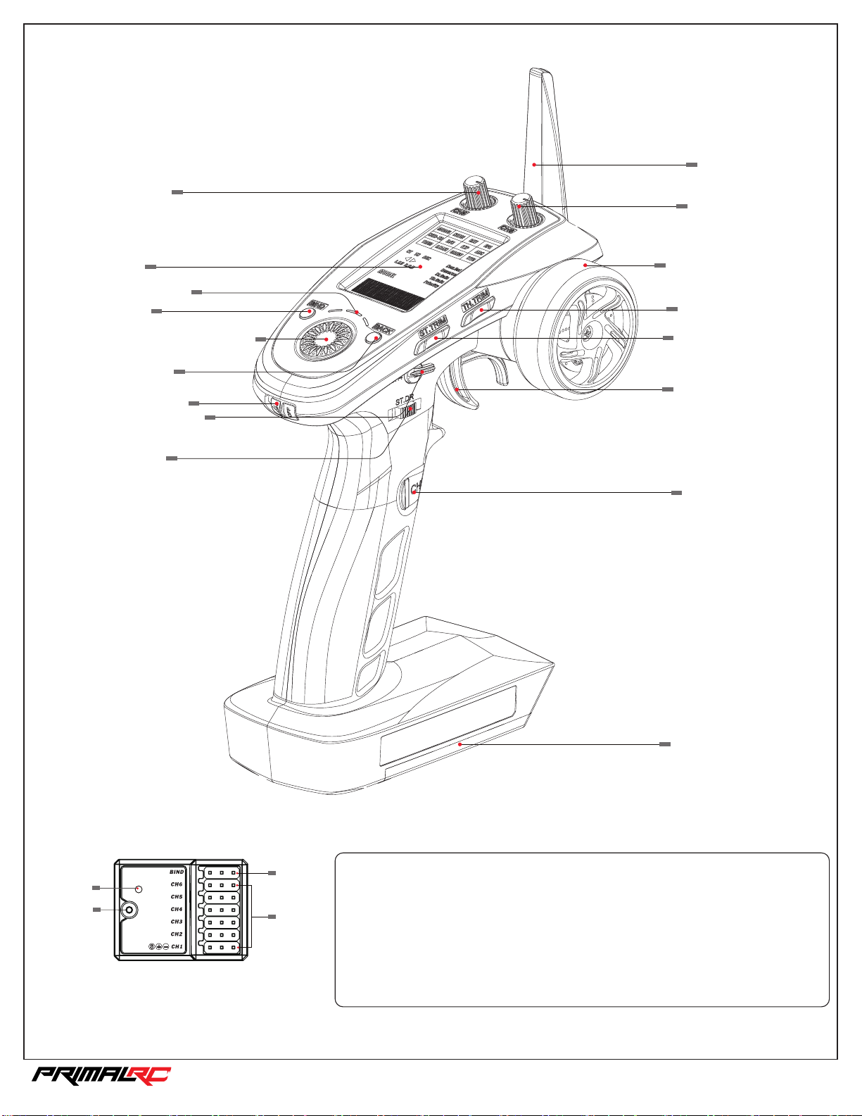
Radio Details
5
Ante nn a
Chan ne l 5
LCD
LED In di cator
BIND
Navi Key
(Rot ate to “Sel ec t”, pre ss t o
“Con fir m”)
BACK /Exit
Power Switch
Reverse Activation
(Cha nn el 4)
Stee ring
D/R
Chan ne l 6
Stee ring Whee l
(Cha nn el 1)
Thro tt le Trim
(Cha nn el 2)
Stee ring Trim
(Cha nn el 1)
Thro tt le/Br ak e
(Cha nn el 2)
Engine Kill Switch
(Cha nn el 3)
LED
Ante nn a
Transmitter
Receiver
Bind /V CC
CH 1-6
Batt ery
Comp ar tment
Bind ing setup
The transmitter and receiver have been pre-bound.
If you are using another transmitter or receiver, follow the steps below to bind the
tran sm itter a nd r eceiv er :
1. Con ne ct the bi nd c able to t he r eceiv er ’s B/ VC C port.
2. Con ne ct powe r to a ny othe r po rt.
3. Pre ss a nd hold t he t ransm it ter’s b in d key and tur n on the tran smitter a t th e same ti me .
4. Onc e bi nding i s co mplet e th e trans mi tter wi ll e xit bin d mo de. Remov e the power a nd
bind c able from t he r eceiv er t hen app ly p ower to t he B /VCC po rt .
5. Che ck t o make su re e veryt hi ng func ti ons as ex pe cted. I f no t repeat th e steps abo ve.
1/5th RAMINATOR MONSTER TRU CK
Page 7

Before You Drive
6
It is extremely important that you read, understand, and follow all instructions in the manuals included with this truck
in order to prevent serious damage to your truck, yourself, and your property. If the user fails to follow these
instructions, it will be considered negligence.
Before assembling and starting your truck, read and understand all manuals and familiarize yourself with the truck
completely. If you decide this truck is not the right choice for your or you do not want to assume responsibility for
your safety, then do not attempt to start it. Do not run the vehicle at all and please contact us to make arrangements
to return your vehicle.
Used vehicles cannot be accepted for returns or exchanges under any circumstances. If you have any questions
about your truck, please email us at [email protected]. Maintenance and replacement parts may be purchased
directly from www.PrimalRC.com.
Follow these steps before each drive session:
1. Mix Gas and 2-Stroke Oil
• Pump gasoline – 87 octane or higher – ethanol-free gas is highly recommended
• 2-stroke oil. Amsoil Saber (recommended): Mix 25:1 ratio (gas/oil)
2. Check to make sure you have a fully charged receiver/servo battery in truck.
3. Check to make sure your transmitter batteries are good.
4. Check all servos (Steering, Throttle, Brake, Reverse).
• DON’T start your vehicle’s engine yet!
• Turn your transmitter on.
• Turn the truck’s battery switch on (located in the back of roll cage).
• Hold the trigger on the transmitter into full brake position. Confirm that the brakes prevent the truck from moving
when you try to push it. If it rolls easily adjust brakes as described in the Assembly Instructions section above.
• Test left and right steering servos by lifting the front of the truck and moving the servos via the transmitter.
Ensure the servos are moving smoothly and there is no excessive play or binding. Adjust as necessary.
• Test throttle servo by giving full throttle and ensure carburetor is moving to full throttle position.
5. Check Remote Engine Kill Switch:
• DON’T start your vehicle’s engine yet!
• Make sure the Manual Engine switch is ON (located on frame under front right wheel well).
• The Remote Engine Kill switch system is located on the truck near your receiver box and has an LED light. The
light is GREEN when it is ready to start and run. If the light is RED this means the Remote Kill switch is on and
your engine will not start. Your transmitter’s third channel button operates the Remote Kill switch.
• To test the Remote Kill switch, press the third channel button on the transmitter. The light should turn RED.
Press it again to change it back to GREEN before you run the truck.
6. Check the Radio Fail Safe: The radio system that comes with the truck has a fail safe automatically installed
ensuring that if your transmitter’s signal is not reaching your truck’s receiver the brakes will be applied
automatically. To test:
• DON’T start your vehicle’s engine yet!
• Turn your transmitter on.
• Turn the truck’s battery switch on (located in the back of roll cage).
• Turn your transmitter off.
• Your brake servo should now apply the brake on its own.
• You have now confirmed that the failsafe is working. Should the receiver lose signal from the transmitter, the
brake will automatically be applied.
• Turn your transmitter back on for normal use.
7. Go over truck to make sure there are no loose screws.
8. Check lug nuts by tightening with provided wrench. Ensure the serrated side of hex nut is facing the rim.
1/5th RAMINATOR MONSTER TRU CK
Page 8
Running Your Truck
7
1. Add 2-Stroke gas and oil mix to gas tank.
2. Turn your transmitter on.
3. Turn the truck’s battery switch on (located in the back of roll cage).
4. Make sure your Manual Engine switch is set to the ON position (located on frame under front right wheel well).
5. Move choke lever to full choke position.
6. Push primer bulb several times, until you see gas going through carburetor and back into gas tank lines.
7. Pull start the engine with a steady, smooth, quick pull until you hear the first pop of the engine trying to start. This is an easy
pull start system. There is no need for aggressive, quick pulls. Do not over-extend the pull-start or your pull starter may
become damaged.
8. Flip the choke lever to off position (down). Make sure it stays in position.
9. Pull start the engine again with short, quick pulls until your engine starts.
Sometimes a little throttle input from the transmitter may be necessary to start the engine.
Be careful to not give too much gas – it may result in the engine flooding.
10. If you are running the truck for the first time, engine break-in is recommended.
The engine break-in process alternates heating and cooling the engine to allow all parts of engine to properly seat
themselves. It also allows 2-stroke oil from the incoming fuel to coat the interior parts of the engine.
Run the engine at varying speeds for periods of 3 to 10 minutes at a time. During this break-in process, never go full
throttle.
Try to stay below half throttle. Always let the engine idle for 30 seconds before turning it off. Allow the engine to cool off for
10 minutes before starting it again. Repeat this process 3 or 4 times (3 or 4 full heat cycles).
11. Reverse Driving Instructions
To drive the truck in reverse, ensure that the truck has come to a complete stop, then switch channel 4 from the
transmitter. Switch to the opposite position – it's a 3-position switch, so be sure to toggle between the furthest positions.
This will cause the servo to active the reverse function in the transmission. Test this by giving it a little gas to confirm that
reverse is engaged. You may need to toggle the switch ON and OFF again to engage if reverse is not working.
To go back to forward driving repeat the process of bringing the truck to a stop and then switching channel 4 to the
opposite position.
Note: Because of the size and weight of the truck, try to avoid steering the truck while it is not moving. This will extend the life
of your steering servos.
Note: This truck is not waterproof. Do not submerge this truck in deep water. Small puddles or shallow water should not be a
problem.
Note: If you are planning on driving this truck in excessive dirt, we recommend that you remove the installed choke.
Follow the Choke Removal Instructions in this manual. It might be more difficult to start the truck without the choke,
however, your engine will last longer because this choke system can let dirt into your engine.
Note: Using a 2S LiPo battery is possible and will provide better steering power, however, the large current will shorten the life
span of the smaller throttle and reverse servos. If you use a LiPo battery, we recommend that you upgrade the throttle and
reverse servos to high-voltage servos.
After You Drive
• Be sure to let the engine idle for 30 seconds to cool before stopping the engine.
• Press the Kill Switch button (channel 3) on your transmitter to shut the engine off.
• Turn battery switch OFF (located in the back of roll cage).
• Turn your transmitter OFF.
VERY IMPORTANT: ALWAYS turn off the truck first, then the receiver, then the transmitter in that order. If your receiver or battery switch is left
ON and your transmitter is OFF the failsafe will cause the servos to overheat and eventually burn out.
• If your truck is wet or dirty, we recommend rinsing the dirt off with a gentle stream of water and then using compressed air to
dry it off.
• Important! Lubricate joint areas and moving parts with WD40 to prevent rust and keep truck working properly for many years
to come.
(example: wheel bearings, suspension links, drive shafts, servo cables)
• Inspect the truck for loose screws, broken and missing parts. We recommend blue lock-tight for screws that are threaded into
aluminum parts that do not have nylon lock nuts.
• If you are storing your truck your truck for a month or more, we recommend draining the gas out of the tank and carburetor.
Love your truck by taking good care of it and it will love you back.
1/5th RAMINATOR MONSTER TRU CK
Page 9

Choke Removal Instructions
8
• Watch the instruction video at www.PrimalRC.com/Video/TruckInstructions.
• Loosen air filter clamp and slide air filter off.
• Remove the two screws that are holding the choke system onto the carburetor. To prevent the carburetor from
falling off while you remove the screws, hold the carburetor in place.
• Remove the choke plate and lever system and reinstall the velocity stack directly onto the carburetor using the
same two screws that you removed earlier, but install 2 additional lock washers on each bolt to act as spacers
and allow for proper tightening.
• Reinstall the air filter and tighten the clamp.
Steering Servo Saver Adjustments
The steering system has both servos linked to an adjustable centralized servo saver system. This system helps
keep the servos from being damaged when force is put on the front wheels. You can adjust the sensitivity of the
system by loosening or tightening the large hex nut on the servo saver spring. Tightening the spring will allow
more control of the steering, however the servos will be more vulnerable to damage upon impact. Loosening the
spring will reduce steering control, but offer more protection for the servos. Finding the optimal ratio is a matter of
personal preference, so test different settings to find one that you prefer.
1/5th RAMINATOR MONSTER TRU CK
Page 10

Brake Adjustments
9
Watch the instruction video at www.PrimalRC.com/Video/TruckInstructions.
Because the brake system is on the drive shafts, this truck can stop very quickly. If your truck is not stopping
quickly brake adjustment is necessary.
This may include changing brake pads and/or rotors, adjusting brake cable tension, and adjusting servo end
points. We recommend that you watch our detailed videos online to learn how to adjust your brakes.
1/5th RAMINATOR MONSTER TRU CK
Page 11

Transmission Gears Adjustment
10
The truck uses a single-speed transmission that has five different gear ratios to choose from. The mid-range
gear set is installed in the truck out-of-the-box (spur/pinion ratio 25:25). Other gear sets that are included with
your truck change the driving and power experience. For crawling, we recommend switching to 20:30 or 23:27
ratio. We recommend 27:23 and 30:20 for optional high-performance engines with greater speeds.
The installed ratio is (25:25) is a good overall gear set that we recommend for common use.
To change the gearing in the transmission: (See diagrams #24 and #25 in this instruction manual)
• Remove the rear drive shaft from the rear output shaft of the transmission (a 4mm hex pin holds it in place).
• Remove the six screws (4mm hex) from the transmission case.
• Remove transmission cover and the two ball bearings that hold the gears on.
• Slide off the two gears and install the gear set with your preferred ratio (pinion gear on the left, spur gear on
the right which is also transmission output shaft)
Note: Ensure that the gears are greased. You can use the grease that is already in the transmission.
Note: The smaller the pinion gear, the slower the truck will drive, but the more low-speed power it will have.
• Reinstall the two bearings, the cover and the rear drive shaft to their original positions.
1/5th RAMINATOR MONSTER TRU CK
Page 12

Troubleshooting Guide
11
The engine doesn’t start or is not running well
o Make sure your gas and oil are mixed properly.
Mix Gas and 2-Stroke Oil
• Pump gasoline – 87 octane or higher – ethanol-free gas is highly recommended
• 2-stroke oil. Amsoil Saber (recommended)
• Mixed 25:1 ratio (gas/oil)
o Follow the instructions in this manual for “Running Your Truck”. If your truck still does not
start, try the following:
• Check to make sure your spark plug is clean and working. Remove the plug from the engine
and inspect the tip. If it is clogged, it will need to be cleaned or replaced. After the plug is
removed, check if the plug is working by:
o Attaching the wire to the top of the plug
o Placing the tip of the plug very close to the metal of the cylinder.
o Pull the pull start a few times. A spark should jump from the plug to the cylinder. If no
spark or a weak spark is observed, replace the plug, ensure the ignition coil and
flywheel are properly gapped, then check again.
o If still no spark - you likely have a problem with the ignition coil and will need to replace
it.
• The Remote Kill Switch may not be working properly and will need to be tested.
• Check to make sure your carburetor is properly tuned. You may need to adjust the screw
slightly in either direction to find correct tuning for your carb.
• Your engine may be flooded. This can happen if you have pushed the primer bulb many
times, or pulled the pull start a lot of times.
o Remove the spark plug and allow all the fuel in the cylinder to evaporate.
• Your compression may be bad. If you have an older engine, the piston rings may need
replacement.
• Check your carb gasket, intake gasket, cylinder gasket, and crankcase gasket. Can you
hear air whooshing out of the cylinder gasket or crankcase gasket when you pull the
starter? Is air leaking in the manifold gasket behind the carb?
o A gasket leak results in a loss of compression and/or improperly mixed fuel and air. An
easy way to check for intake leaks is to spray the intake manifold and area surrounding
it with WD-40. If the idle changes after you spray the WD-40, there is an intake air leak.
o Common areas for leaks are between the manifold and the cylinder, and between the
carb and the intake manifold. Inspect the manifold, carb gasket, and intake gasket for
cracks or other signs of damage, replace if necessary.
• Make sure your gas cap is venting properly. There should be a small hole in the plastic cap
and bladder. If it becomes blocked or clogged it can cause issues. Also check to make sure
fuel lines are connected correctly, the fuel lines aren't cut, and the fuel filter is attached.
• Make sure there is no debris (grass/dirt/etc.) clogging the pull start, air filter or engine. This
can result in the engine running too hot and becoming overheated.
1/5th RAMINATOR MONSTER TRU CK
Page 13
Troubleshooting Guide (continued)
12
The engine doesn’t idle well
o If the idle is too low, turn the carburetor idle screw clockwise to raise idle. If the idle is too high turn it
counterclockwise until the desired idle is reached. Idling as low as possible is recommended without the
engine stalling. The clutch may start to engage, preventing the reverse function from working properly.
The servos aren’t responding, or the transmitter is not connecting
o Check that transmitter switch is on
o Check that truck’s battery switch is on
o Check the wire connections. Make sure they're intact and connected properly.
o Check that your batteries are charged
o Check to make sure your transmitter and receiver are bound.
The servos aren’t moving in correct direction
o Check servo reverse functions on the transmitter.
The brakes are not working, but the brake servos are moving
o Adjust cable wire to ensure that the brake is pulling properly on the calipers.
o Check to make sure brake pads are not worn out.
o Check that drive line axle pins and driveshaft pins are not broken.
Reverse is not working
o Make sure you stop the truck from rolling before switching to reverse.
o Check that your idle is low. If idle is too high, The clutch may start to engage, preventing the reverse
function from working properly.
o Adjust the reverse servo cable to ensure that it is pulling enough to engage reverse properly.
1/5th RAMINATOR MONSTER TRU CK
Page 14
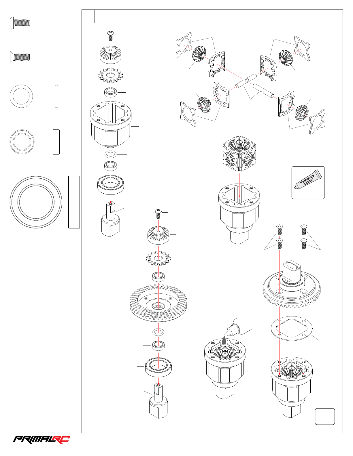
Differential Assembly
13
1
MBS4 010
M4×10m m
MFS4 01 2
M4×12m m
ORS1 40 20
O-Ri ng D 14×2mm
BBS1 01504
Bear ing 10×15×4mm
×4
×8
×4
×8
MBS4 010
RMT1 07
RMT1 08
BBS1 01504
RMT0 35
ORS1 40 20
BBS1 01504
BBS2 03207
RMT1 07
RMT1 07
RMT1 08
RMT1 08
RMT1 08
RMT1 07
RMT1 07
RMT1 06
RMT1 08
USE
ALWAYS
BBS2 03207
Bear ing 20×32×7mm
×4
RMT0 86
ORS1 40 20
BBS1 01504
BBS2 03207
RMT0 51
MBS4 010
RMT1 07
RMT1 08
BBS1 01504
#200 00cst
Diff Oil
MFS4 01 2
MFS4 01 2
RMT1 45
RMT0 51
×2
1/5th RAMINATOR MONSTER TRU CK
Page 15
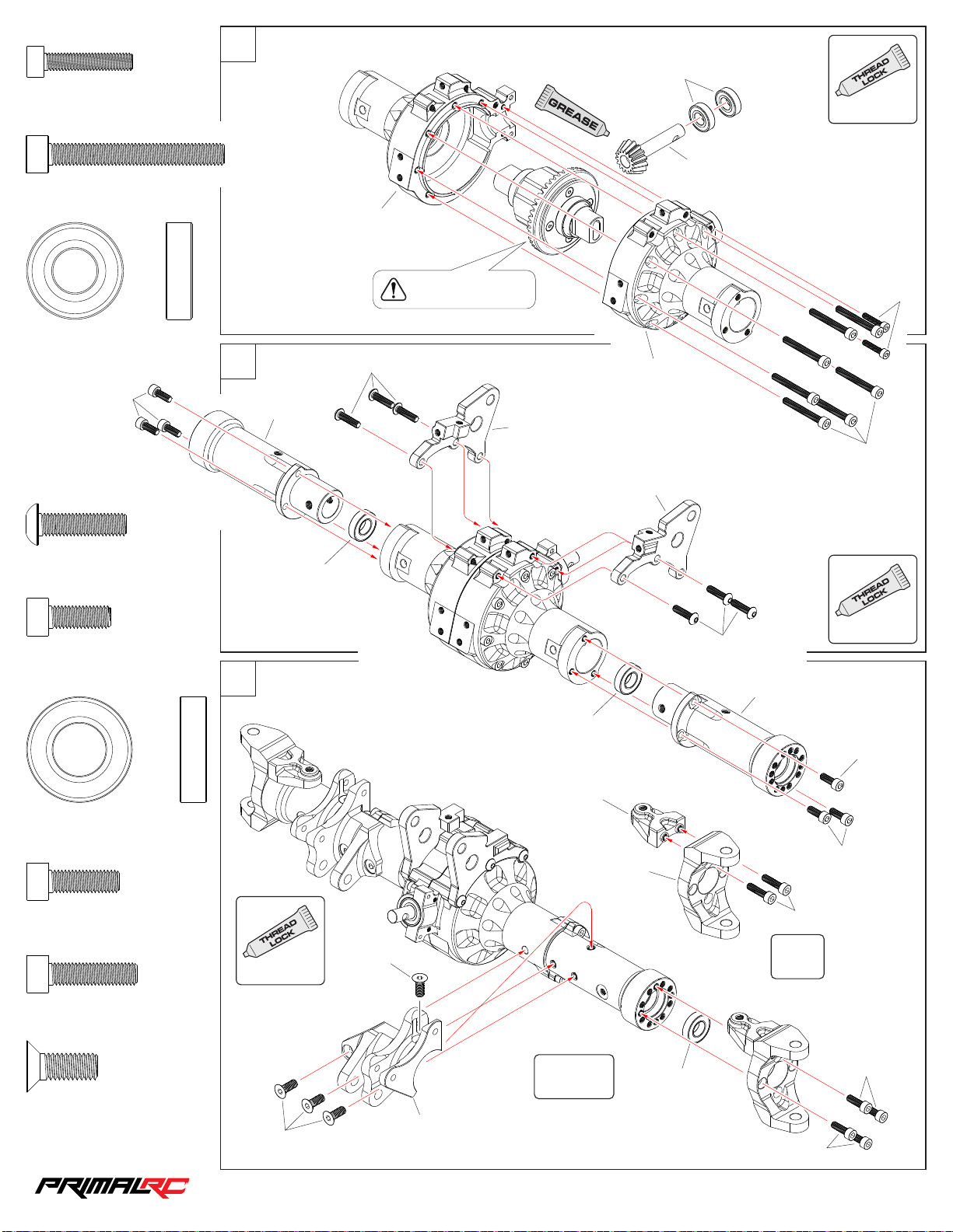
MCS4 020
14
M4×20m m
MCS5 040
M5×40m m
×2
×7
Front Axle Assembly
2
RMT0 01
USE
BBS1 02206
ALWAYS
RMT0 85
BBS1 02206
Bear ing 10×22×6mm
MCS5 014
MBS5 020
M5×20m m
MCS5 014
M5×14m m
×6
×6
×2
3
RMT0 02
4
MBS5 020
BBS1 22406
Noti ce t he dire ct ion
of the d if fe renti al
RMT0 07
MCS4 020
RMT0 01
MCS5 040
RMT0 07
USE
ALWAYS
MBS5 020
RMT0 02
BBS1 22406
BBS1 22406
Bear ing 12×24×6mm
MCS5 016
M5×16m m
MCS5 020
M5×20m m
MFS6 01 6
M6×16m m
×8
×4
×8
×4
USE
ALWAYS
MFS6 01 6
MFS6 01 6
RMT0 06
RMT0 03
L/R
MCS5 014
MCS5 014
RMT0 03
MCS5 020
×2
BBS1 22406
1/5th RAMINATOR MONSTER TRU CK
MCS5 016
MCS5 016
Page 16
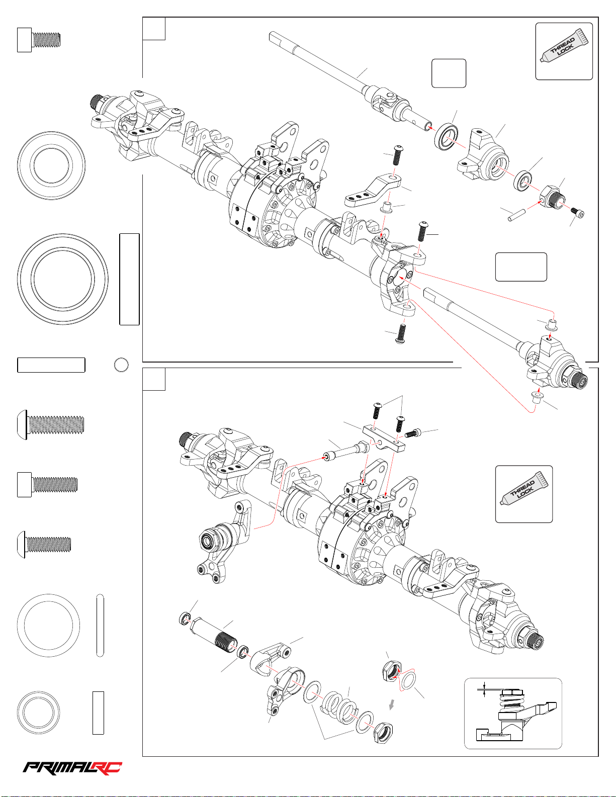
5
15
USE
MCS5 010
M5×10m m
BBS1 22406
Bear ing 12×24×6mm
BBS2 03207
Bear ing 20×32×7mm
×2
×2
×2
RMT0 52
MBS6 020
MBS6 020
RMT0 19
RMT0 44
×2
BBS2 03207
MBS6 020
ALWAYS
RMT0 04
BBS1 22406
RMT0 46
PINS 50 24
MCS5 010
L/R
RMT0 44
PINS 50 24
M5×24m m
MBS6 020
M6×20m m
MCS5 016
M5×16m m
MBS5 016
M5×16m m
ORS2 20 25
O-Ri ng D 22×2.5m m
×2
×6
×1
×2
×1
6
BBS1 01504
BBS1 01504
RMT0 39
RMT0 41
RMT0 09
RMT0 16
RMT1 38
MBS5 016
RMT0 44
MCS5 016
USE
ALWAYS
RMT0 39
BBS1 01504
Bear ing 10×15×4mm
×2
ORS2 20 25
1 mm
RMT0 09
MWS2 02 810
1/5th RAMINATOR MONSTER TRU CK
Page 17
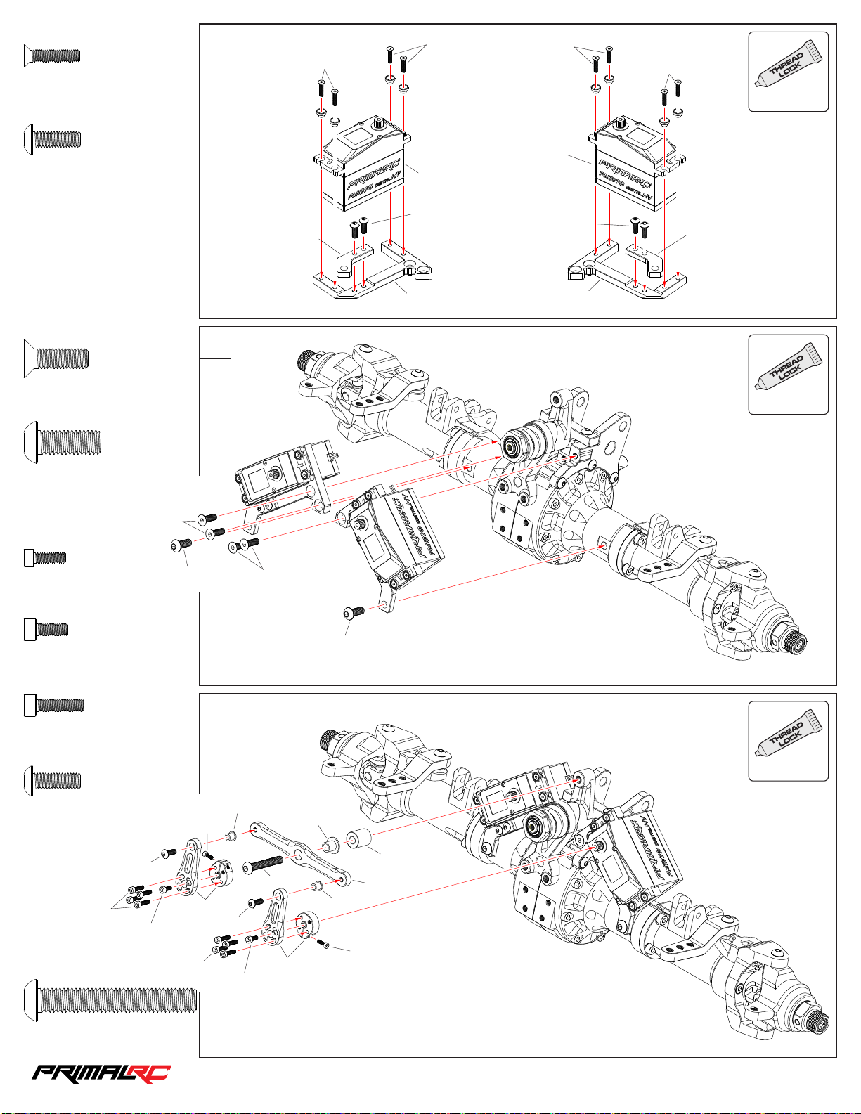
MFS3 01 4
16
M3×14m m
MBS4 012
M4×12m m
×8
×4
7
MFS3 01 4
MFS3 01 4
PRE0 05
MFS3 01 4
PRE0 05
USE
MFS3 01 4
ALWAYS
MFS5 01 6
M5×16m m
MBS6 016
M6×16m m
MCS2 508
M2.5×8 mm
×4
×2
MFS5 01 6
×2
MBS6 016
8
RMT0 15
MFS5 01 6
MBS4 012
RMT0 15
MBS4 012
RMT0 15
RMT0 15
USE
ALWAYS
MCS3 008
M3×8mm
MCS3 012
M3×12m m
MBS4 012
M4×12m m
MCS3 012
MBS6 040
M6×40m m
×2
×2
×2
MBS4 012
MCS3 008
×1
MCS2 508
RMT0 18
MCS3 012
9
RMT1 03
MBS4 012
MCS3 008
MBS6 040
RMT0 18
MBS6 016
USE
ALWAYS
RMT0 44
RMT0 42
RMT0 17
RMT1 03
MCS2 508
1/5th RAMINATOR MONSTER TRU CK
Page 18
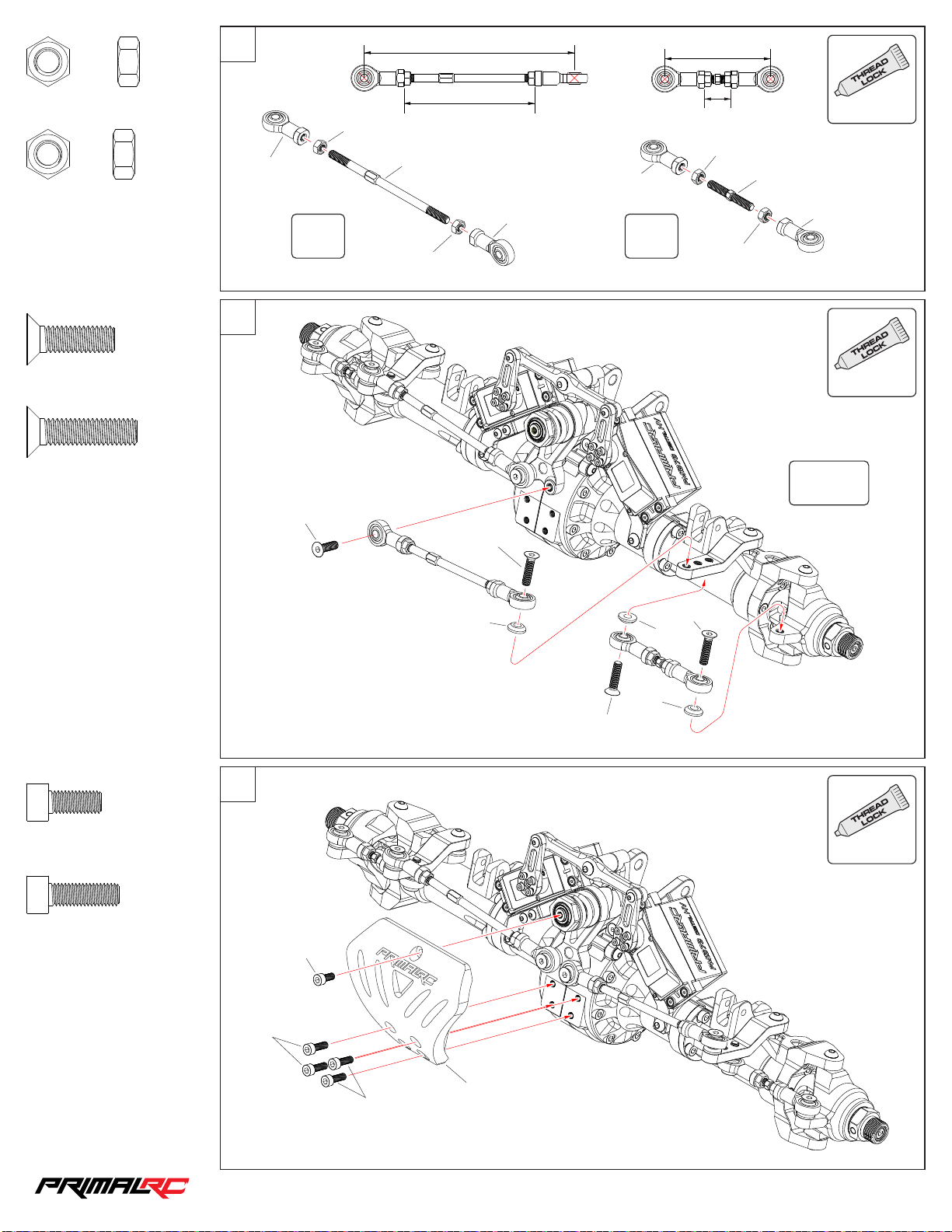
10
17
159 mm
80 mm
USE
MNNS 60
M6 Nut
MNRS 60
M6 Rev erse Nut
MFS6 02 0
M6×20m m
MFS6 02 5
M6×25m m
×2
×6
×4
×4
11
99 mm
MNRS 60
RMT111
RMT0 50
RMT110
×2 ×2
MNNS 60
MFS6 02 0
MFS6 02 5
RMT111
20 mm
MNRS 60
MNNS 60
ALWAYS
RMT0 49
RMT110
USE
ALWAYS
L/R
MCS5 012
M5×12m m
MCS5 016
M5×16m m
×1
×4
12
MCS5 012
MCS5 016
RMT0 80
MFS6 02 5
RMT0 80
RMT0 80
MFS6 02 5
USE
ALWAYS
RMT0 38
MCS5 016
1/5th RAMINATOR MONSTER TRU CK
Page 19
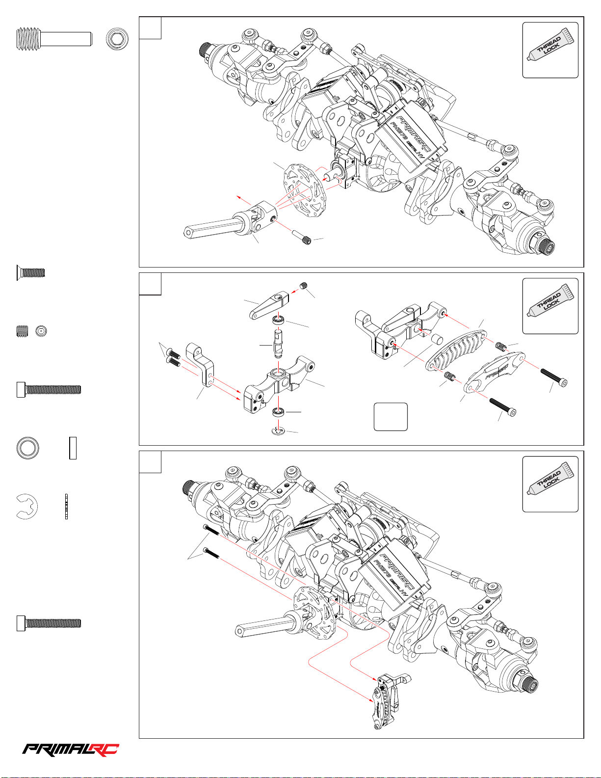
13
18
USE
RMT0 55
M8×27m m
MFS3 01 0
M3×10m m
MSS4 004
M4×4mm
×1
×4
×2
14
MFS3 01 0
RMT0 54
RMT0 96
RMT0 97
RMT0 36
RMT0 55
MSS4 004
BBS0 50825
ALWAYS
USE
RMT0 95
ALWAYS
RMT0 99
RMT0 97
MCS3 020
M3×20m m
BBS0 50825
Bear ing 5×8×2.5mm
MES4 0
E-cl ip 4mm
MCS3 020
M3×20m m
×4
×2
×2
×4
15
RMT0 96
MCS3 020
RMT0 34
BBS0 50825
MES4 0
×2
RMT0 99
RMT0 95
MCS3 020
MCS3 020
USE
ALWAYS
1/5th RAMINATOR MONSTER TRU CK
Page 20
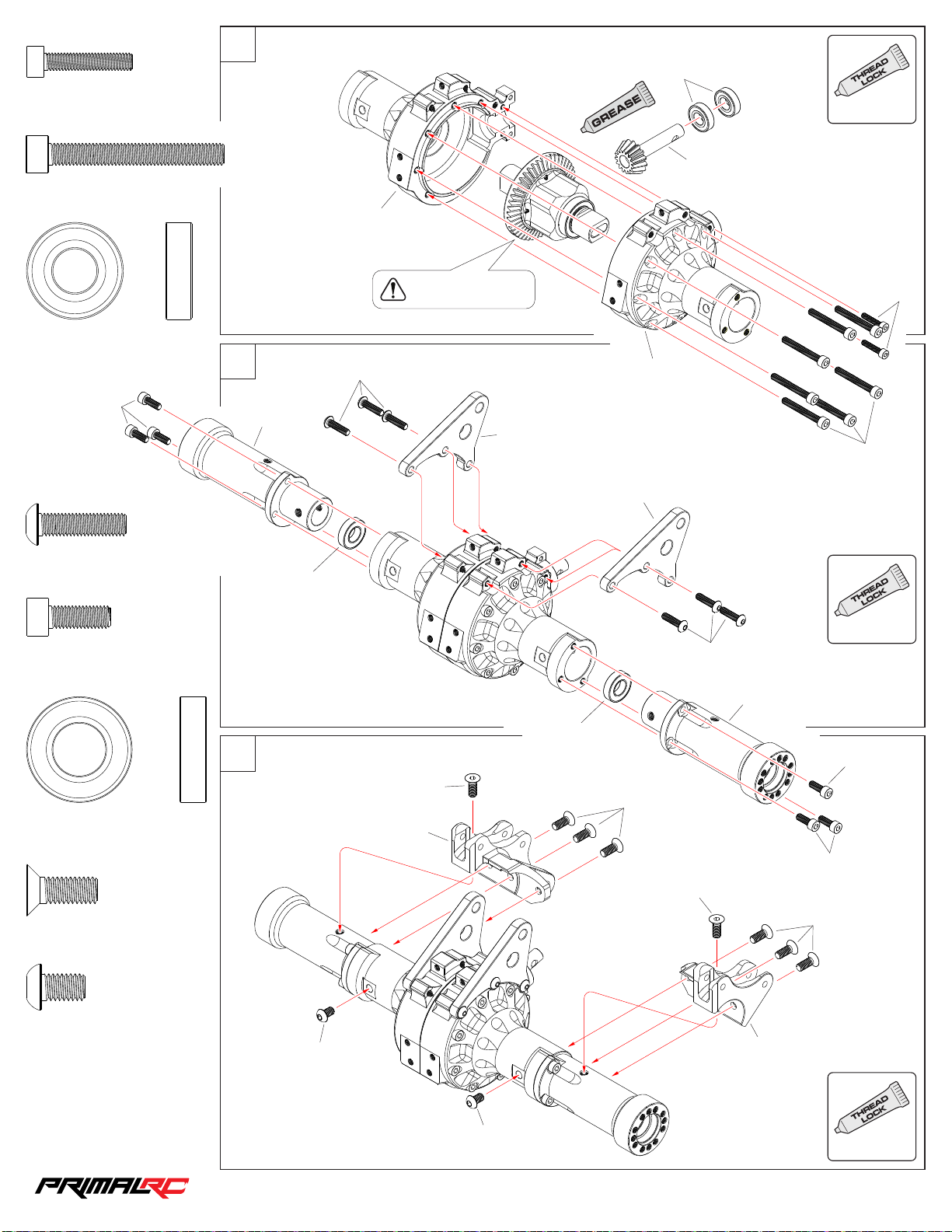
MCS4 020
19
M4×20m m
MCS5 040
M5×40m m
×2
×7
Rear Axle Assembly
16
RMT0 01
USE
BBS1 02206
ALWAYS
RMT0 85
BBS1 02206
Bear ing 10×22×6mm
MCS5 014
MBS5 020
M5×20m m
MCS5 014
M5×14m m
×6
×6
×2
17
RMT0 02
MBS5 020
BBS1 22406
Noti ce t he dire ct ion
of the d if fe renti al
RMT0 08
MCS4 020
RMT0 01
MCS5 040
RMT0 08
USE
ALWAYS
MBS5 020
RMT0 02
BBS1 22406
BBS1 22406
Bear ing 12×24×6mm
MFS6 01 6
M6×16m m
MBS6 010
M6×10m m
×8
×2
×2
18
MBS6 010
MCS5 014
MFS6 01 6
MFS6 01 6
RMT0 06
MCS5 014
MFS6 01 6
MFS6 01 6
RMT0 06
USE
MBS6 010
ALWAYS
1/5th RAMINATOR MONSTER TRU CK
Page 21
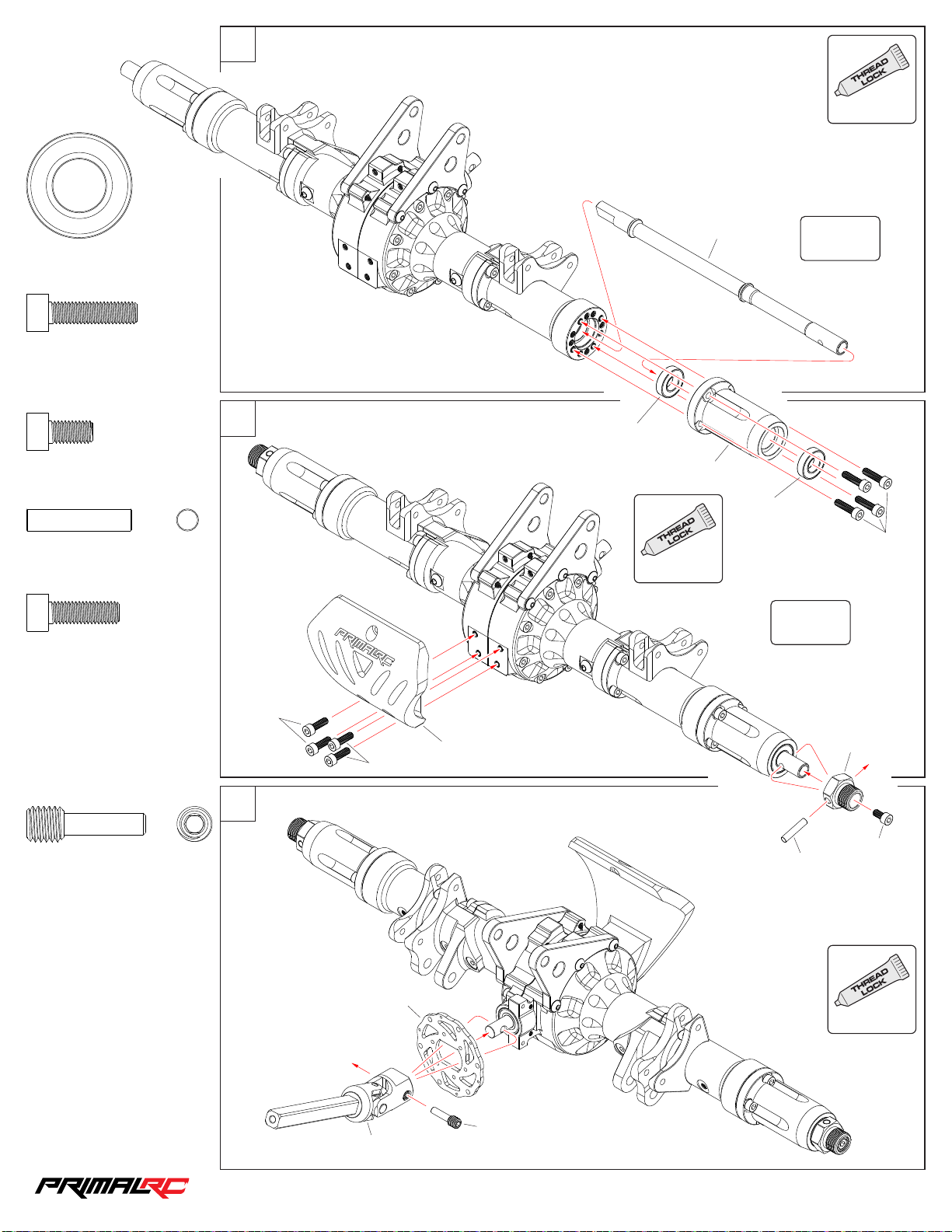
BBS1 22406
20
Bear ing 12×24×6mm
×4
19
USE
ALWAYS
RMT0 53
L/R
MCS5 020
M5×20m m
MCS5 010
M5×10m m
PINS 50 24
M5×24m m
MCS5 016
M5×16m m
×8
×2
×2
×4
20
MCS5 016
MCS5 016
RMT0 38
BBS1 22406
USE
ALWAYS
RMT0 05
BBS1 22406
MCS5 020
L/R
RMT0 46
RMT0 55
M8×27m m
×1
21
MCS5 010
PINS 50 24
USE
RMT0 36
ALWAYS
RMT0 55
RMT0 54
1/5th RAMINATOR MONSTER TRU CK
Page 22
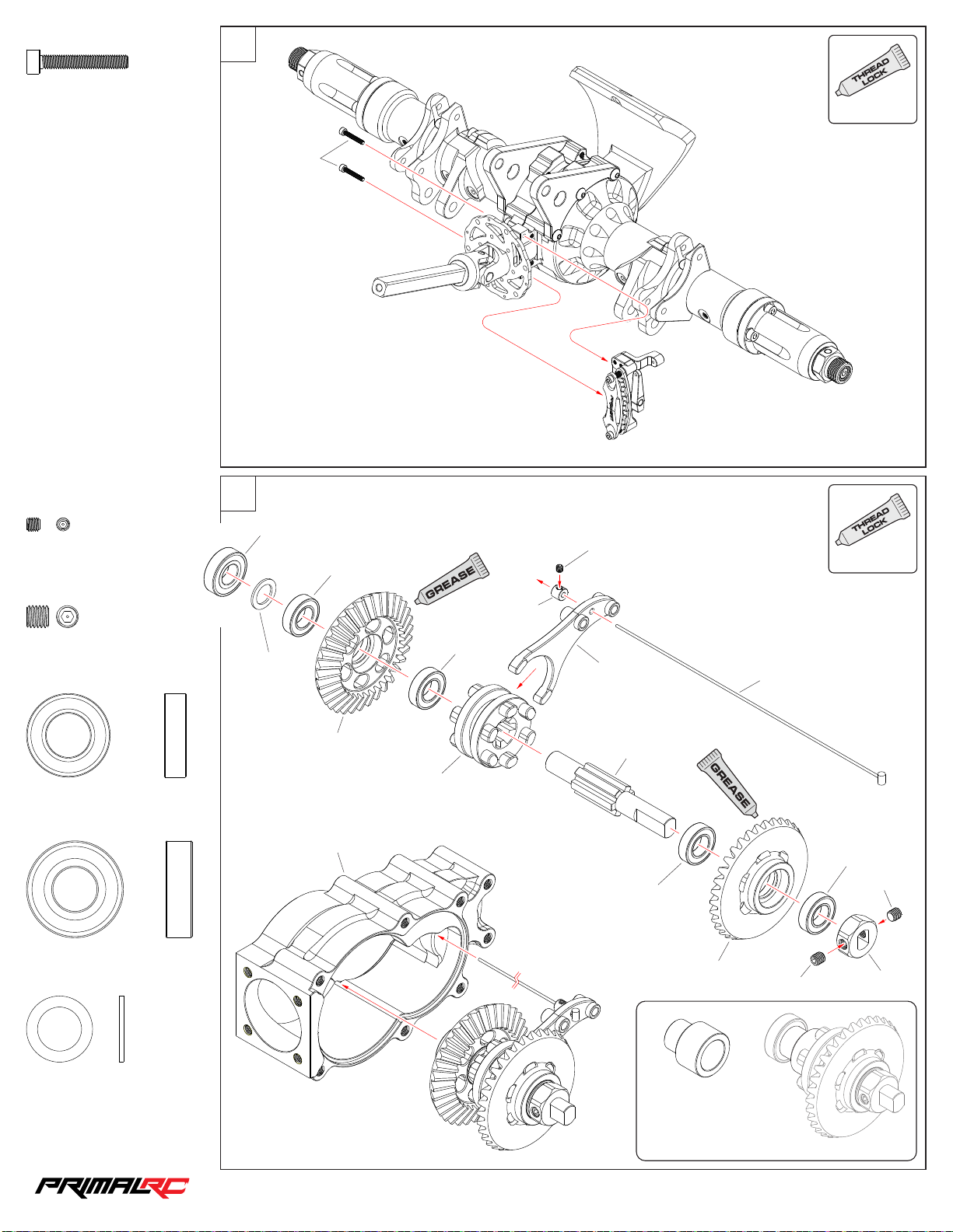
22
21
USE
MCS3 020
M3×20m m
MSS3 003
M3×3mm
×2
×1
MCS3 020
Transmission Assembly
23
BBS1 02206
BBS1 01905
ALWAYS
USE
MSS3 003
ALWAYS
MSS5 005
M5×5mm
BBS1 01905
Bear ing 10×19×5mm
BBS1 02206
Bear ing 10×22×6mm
×2
×4
×1
MWS1 01 510
RMT0 88
RMT0 11
BBS1 01905
RMT0 64
RMT1 01
RMT0 13
RMT0 65
BBS1 01905
RMT0 88
RMT1 41
MSS5 005
BBS1 01905
MSS5 005
RMT0 63
MWS1 01 510
Was her 10×15×1mm
×1
If you d on ’t want t he
reve rse funct io n, repl ac e
the re ar s ide bev el g ear
and be arings wi th t he shaf t
spac er packed i n th e box.
1/5th RAMINATOR MONSTER TRU CK
Page 23
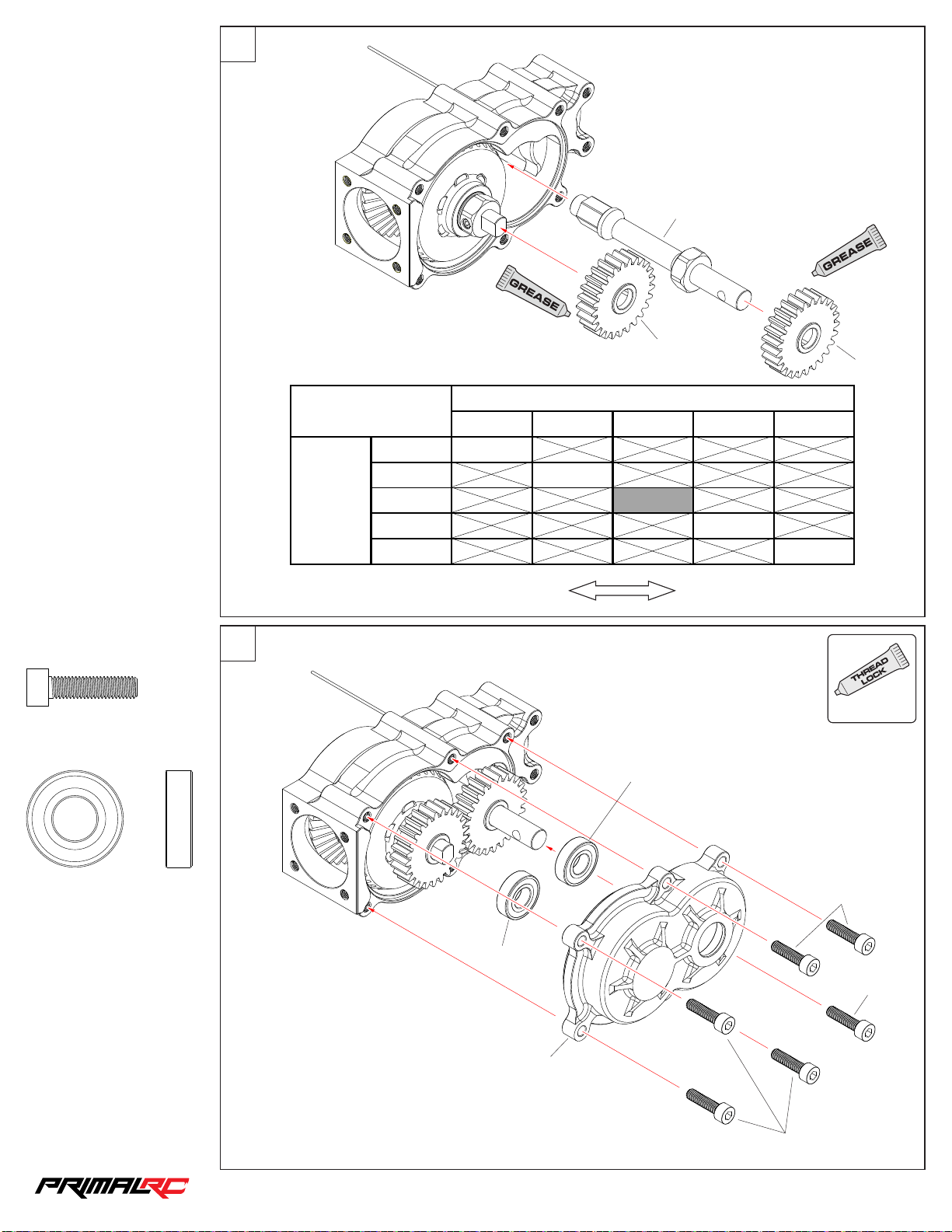
24
30 27 25 23 20
20 27
23 21.1 3
25 18
27 15.3 3
30 12
Spur
Pinio n
To tal G e a r Ratio
22
RMT0 66
RMT0 92
RMT0 92
MCS5 020
M5×20m m
BBS1 02206
Bear ing 10×22×6mm
×6
×2
25
Low sp eed
More t or que
BBS1 02206
High s peed
Less t or que
USE
ALWAYS
BBS1 02206
MCS5 020
MCS5 020
RMT0 12
MCS5 020
1/5th RAMINATOR MONSTER TRU CK
Page 24
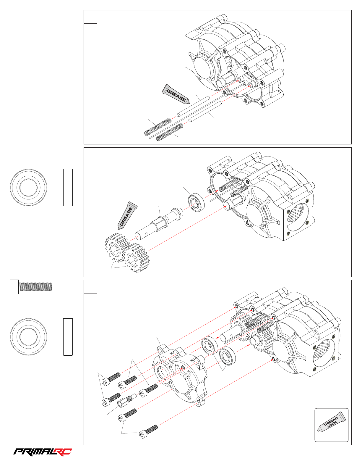
26
23
RMT0 69
BBS1 02206
Bear ing 10×22×6mm
×1
27
RMT0 89
28
RMT1 39
RMT0 67
RMT0 69
RMT1 39
BBS1 02206
MCS5 020
M5×20m m
BBS1 02206
Bear ing 10×22×6mm
×6
×2
MCS5 020
RMT0 68
MCS5 020
RMT0 12
MCS5 020
BBS1 02206
USE
ALWAYS
1/5th RAMINATOR MONSTER TRU CK
Page 25
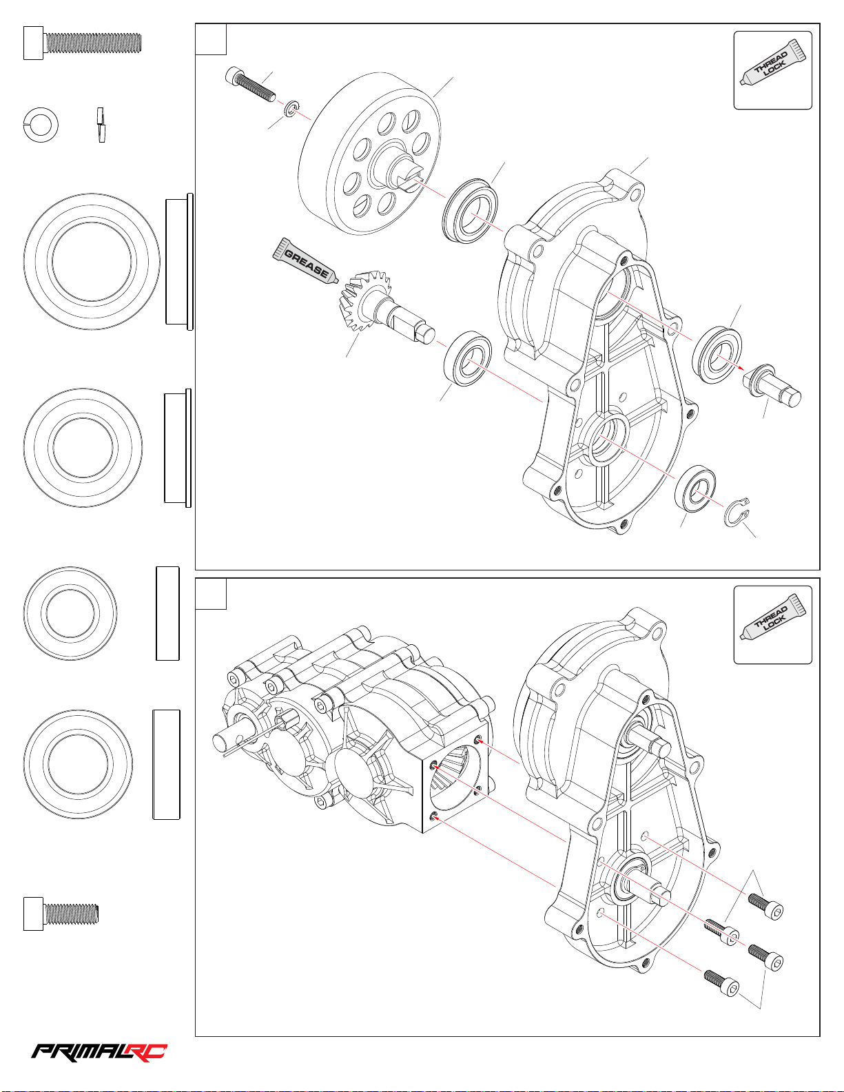
MCS5 025
24
M5×25m m
MPS5 0
Spri ng Washe r M5
×1
×1
29
MCS5 025
MPS5 0
RMT0 57
FBS2 03 207
USE
ALWAYS
RMT0 10
FBS1 52 807
FBS2 03 207
Flan ge B earin g 20×3 2×7mm
FBS1 52 807
Flan ge B earin g 15×2 8×7mm
BBS1 22406
Bear ing 12×24×6mm
×1
×1
×1
30
RMT0 87
BBS1 52807
RMT0 56
BBS1 22406
MCDS 12
USE
ALWAYS
BBS1 52807
Bear ing 15×28×7mm
MCS5 014
M5×14m m
×1
MCS5 014
×4
MCS5 014
1/5th RAMINATOR MONSTER TRU CK
Page 26
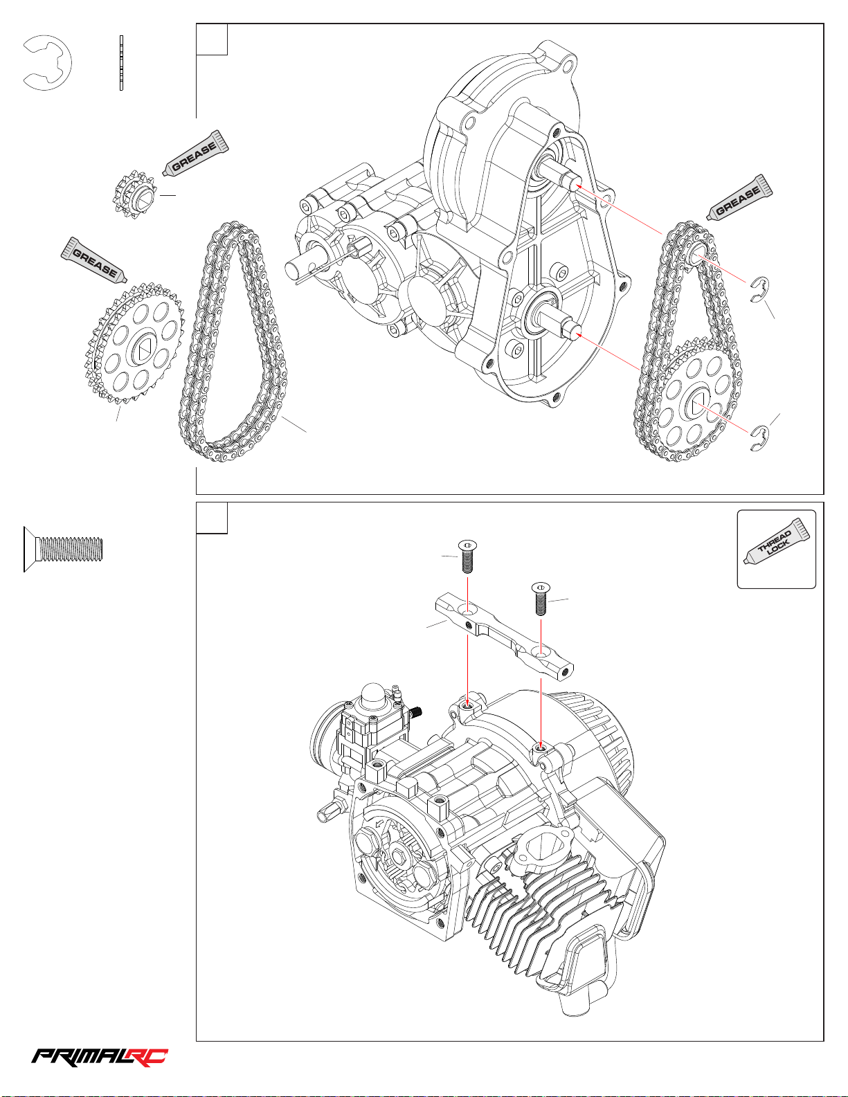
31
25
MES7 0
E-cl ip 7mm
RMT0 84
×2
RMT0 83
MES7 0
MES7 0
RMT0 93
MFS6 02 0
M6×20m m
×2
Engine Assembly
32
USE
MFS6 02 0
ALWAYS
MFS6 02 0
RMT0 14
1/5th RAMINATOR MONSTER TRU CK
Page 27
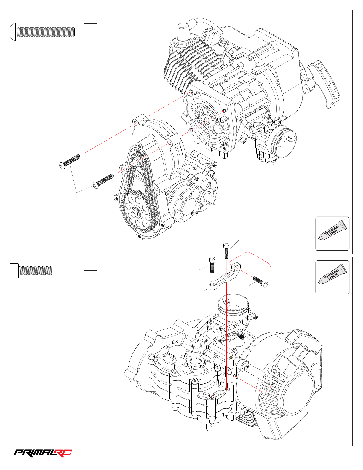
33
26
MBS6 035
M6×35m m
×2
MBS6 035
MCS5 020
M5×20m m
×3
34
MCS5 020
RMT0 14
MCS5 020
MCS5 020
USE
ALWAYS
USE
ALWAYS
1/5th RAMINATOR MONSTER TRU CK
Page 28
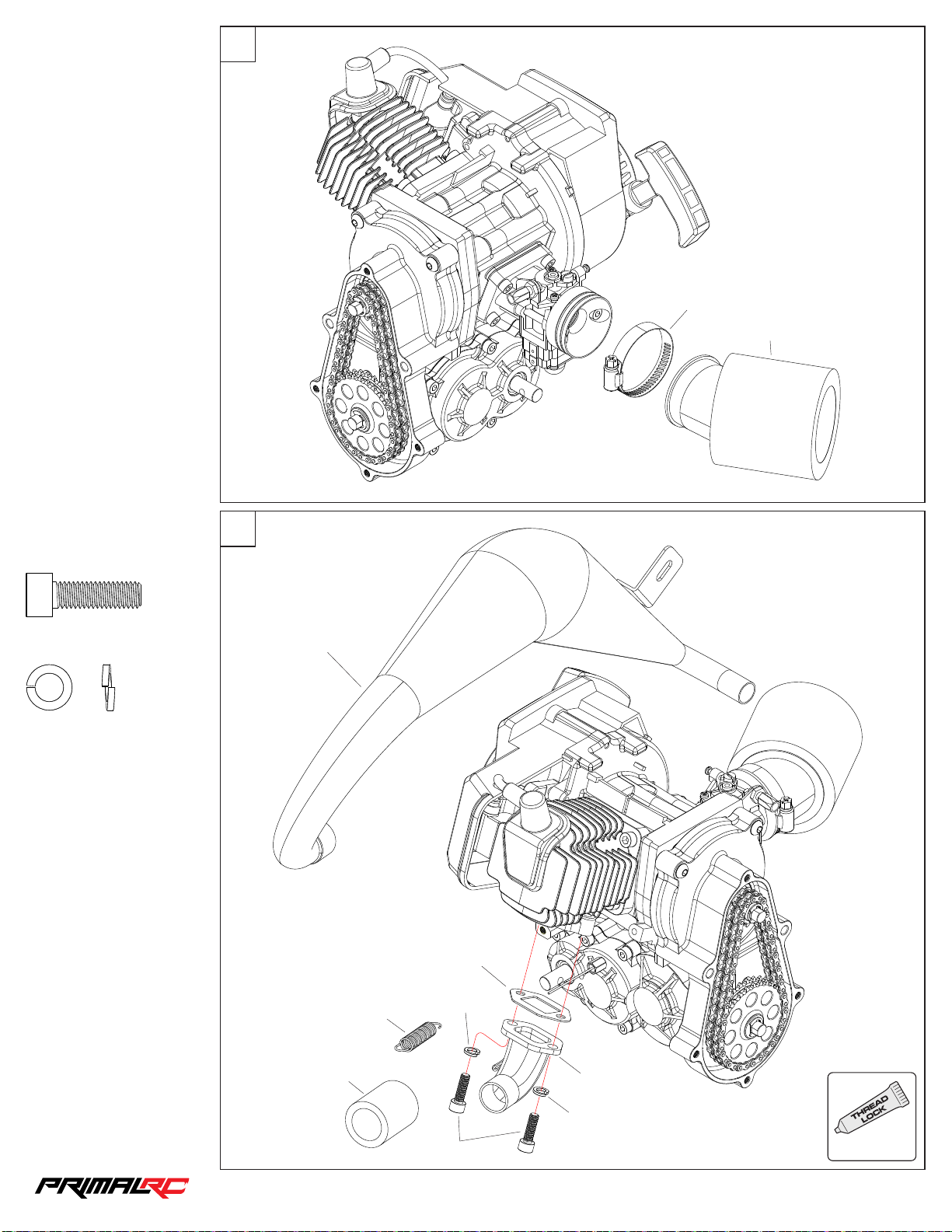
35
27
RMT1 47
RMT1 47
MCS6 020
M6×20m m
MPS6 0
Spri ng Washe r M6
×2
36
RMT1 48
×2
RMT1 49
RMT1 48
RMT1 48
MPS6 0
MCS6 020
RMT1 48
MPS6 0
USE
ALWAYS
1/5th RAMINATOR MONSTER TRU CK
Page 29
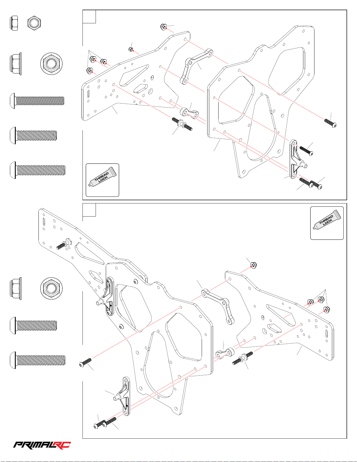
Chassis Assembly
28
37
MNS6 0
MNS5 0
M5 Nyl on Lock Nut
MNS6 0
M6 Nyl on Lock Nut
MBS5 030
M5×30m m
MBS6 025
M6×25m m
MBS6 030
M6×30m m
×1
×2
×1
×1
×4
MNS6 0
USE
ALWAYS
RMT0 22
MNS5 0
RMT0 78
RMT0 23
RMT0 23
MBS6 025
MBS5 030
RMT0 20
MBS6 025
RMT1 26
MBS6 030
MNS6 0
M6 Nyl on Lock Nut
MBS6 025
M6×25m m
MBS6 030
M6×30m m
×2
×1
×4
38
MBS6 025
RMT1 26
USE
ALWAYS
MNS6 0
RMT0 23
MNS6 0
RMT0 23
RMT0 22
RMT0 78
MBS6 025
MBS6 030
1/5th RAMINATOR MONSTER TRU CK
Page 30
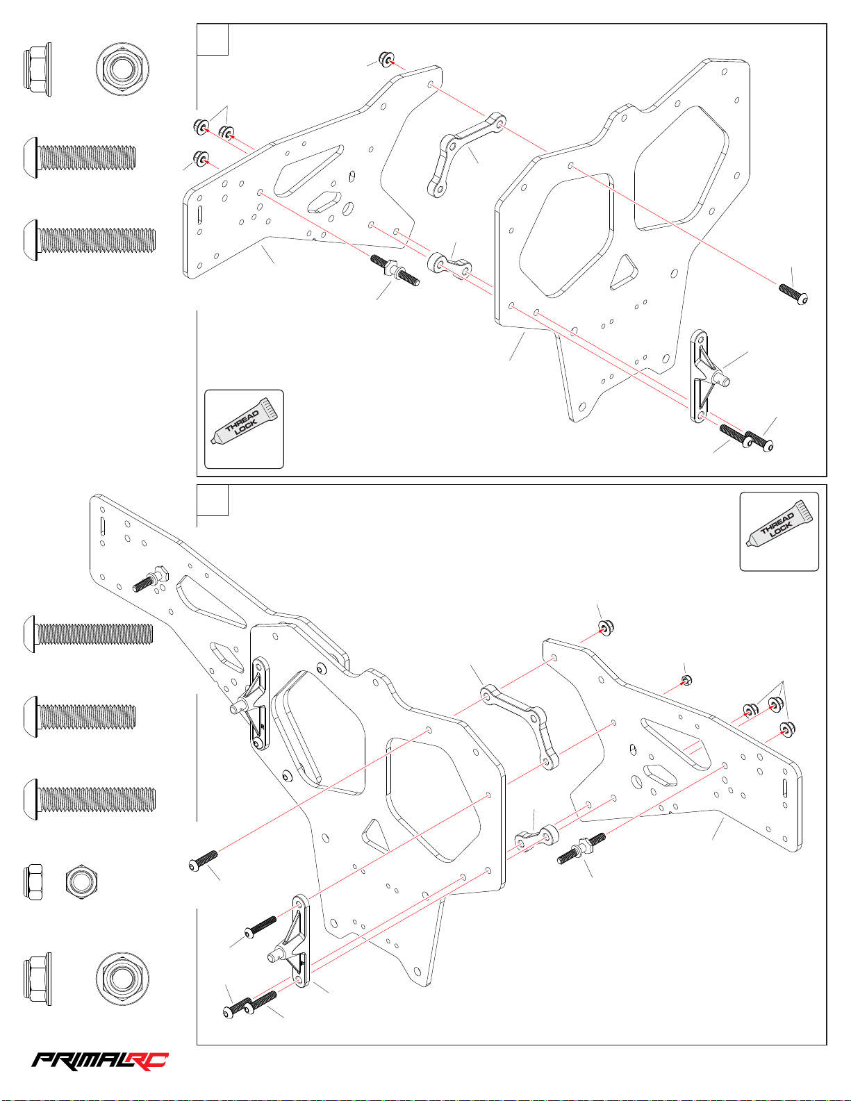
39
29
MNS6 0
MNS6 0
M6 Nyl on Lock Nut
MBS6 025
M6×25m m
MBS6 030
M6×30m m
×2
×1
×4
MNS6 0
MNS6 0
USE
ALWAYS
RMT0 22
RMT0 23
RMT0 23
MBS6 025
RMT0 78
RMT1 26
RMT0 21
MBS6 025
MBS6 030
MBS5 030
M5×30m m
MBS6 025
M6×25m m
MBS6 030
M6×30m m
×1
×2
×1
40
MBS6 025
RMT0 23
USE
ALWAYS
MNS6 0
MNS5 0
MNS6 0
RMT0 23
RMT0 22
RMT0 78
MNS5 0
M5 Nyl on Lock Nut
MNS6 0
M6 Nyl on Lock Nut
×1
×4
MBS5 030
MBS6 025
RMT1 26
MBS6 030
1/5th RAMINATOR MONSTER TRU CK
Page 31
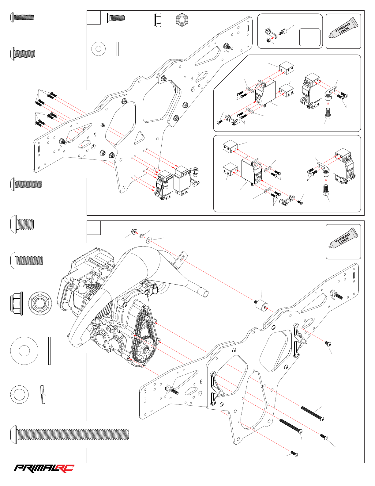
MBS3 012
30
M3×12m m
×8
41
MFS3 01 0
M3×10m m
×2
MNS4 0
M4 Nyl on Lock Nut
×2
RMT0 30
MNS4 0
RMT0 62
×2
USE
ALWAYS
MBS4 012
M4×12m m
MBS4 016
MBS4 016
MBS4 016
M4×16m m
MBS6 010
M6×10m m
×4
×8
×1
MWS0 30 810
Was her 3×8×1mm
42
MNS6 0
×8
MPS6 0
MWS0 61 612
MWS0 30 810
MBS3 012
MFS3 01 0
RMT0 32
PRE0 04
MWS0 30 810
RMT0 32
MWS0 30 810
MBS3 012
RMT0 32
PRE0 04
MWS0 30 810
MBS3 012
MBS3 012
Reve rse Servo As sembly
RMT0 32
RMT0 98
Thro tt le Serv o Ass embly
RMT0 29
MBS4 012
MFS3 01 0
RMT0 29
MBS4 012
RMT0 98
USE
ALWAYS
MBS5 016
M5×16m m
MNS6 0
M6 Nyl on Lock Nut
MWS0 61 612
Was her 6×16×1.2m m
MPS6 0
Spri ng Washe r M6
MBS6 065
M6×65m m
×2
×2
RMT1 48
×1
MBS6 010
×1
MBS6 065
×1
MBS6 065
MBS5 016
MBS5 016
1/5th RAMINATOR MONSTER TRU CK
Page 32
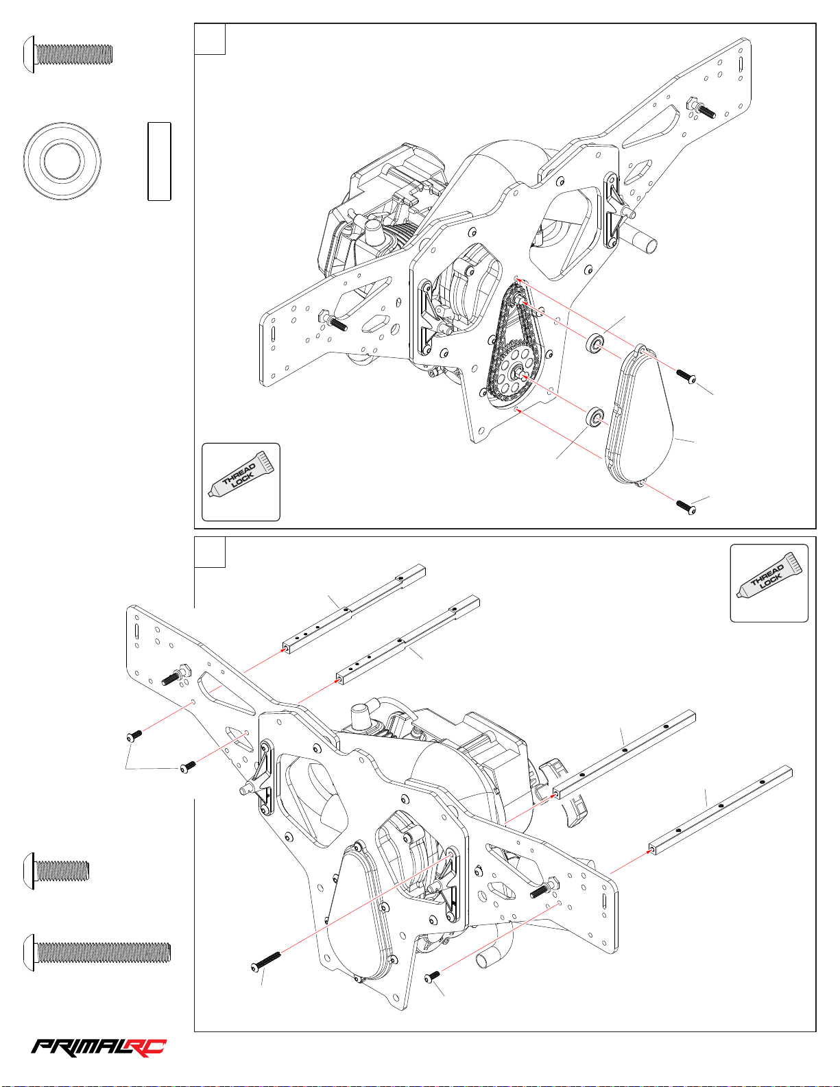
43
31
MBS5 020
M5×20m m
BBS0 92006
Bear ing 9×20×6mm
×2
×2
USE
BBS0 92006
MBS5 020
RMT0 10
BBS0 92006
MBS5 014
44
MBS5 020
ALWAYS
USE
RMT0 25
ALWAYS
RMT0 25
RMT0 24
RMT0 24
MBS5 014
M5×14m m
MBS5 035
M5×35m m
×3
×1
MBS5 035
MBS5 014
1/5th RAMINATOR MONSTER TRU CK
Page 33
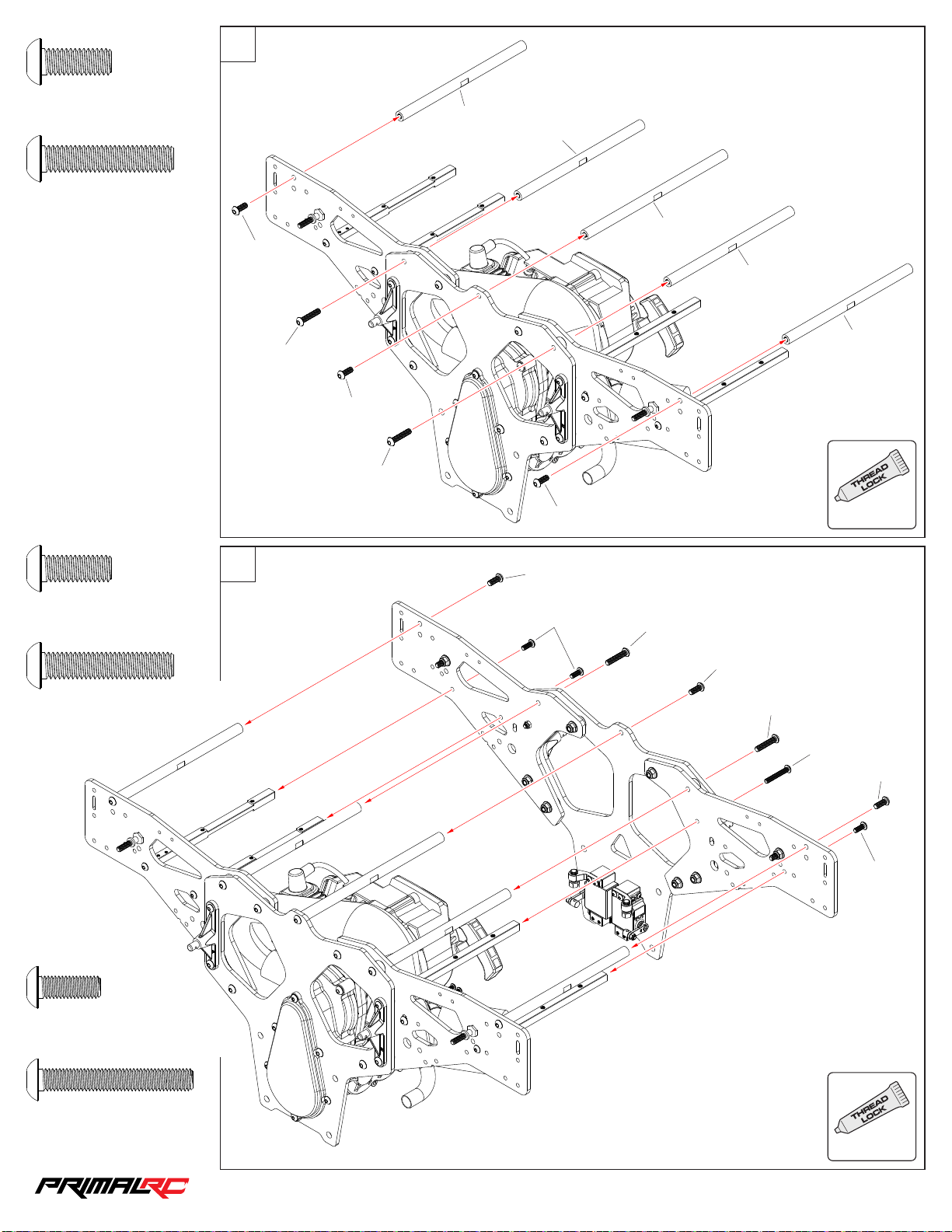
45
32
MBS6 016
M6×16m m
MBS6 030
M6×30m m
×3
×2
MBS6 016
MBS6 030
MBS6 016
MBS6 030
RMT0 58
198m m
198m m
RMT0 58
MBS6 016
RMT0 59
224m m
RMT0 58
198m m
RMT0 58
198m m
USE
ALWAYS
MBS6 016
M6×16m m
MBS6 030
M6×30m m
×3
×2
46
MBS6 016
MBS5 014
MBS6 030
MBS6 016
MBS6 030
MBS5 035
MBS6 016
MBS5 014
MBS5 014
M5×14m m
MBS5 035
M5×35m m
×3
USE
×1
ALWAYS
1/5th RAMINATOR MONSTER TRU CK
Page 34
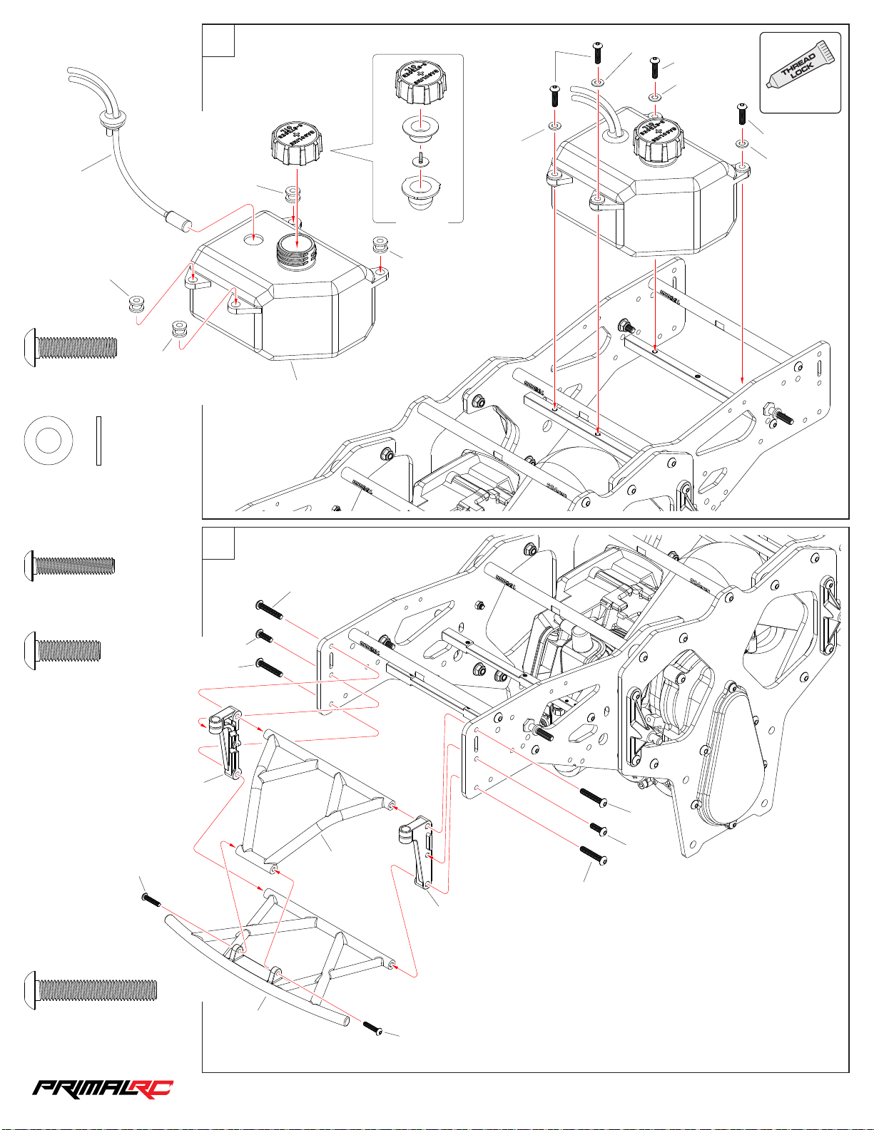
Fuel Tank Assembly
33
47
MBS5 020
MWS0 61 212
USE
MBS5 020
MWS0 61 212
ALWAYS
RMT115
RMT116
MBS5 020
M5×20m m
MWS0 61 212
Was her 6×12×1.2m m
×4
MWS0 61 212
MBS5 020
MWS0 61 212
RMT116
RMT115
RMT116
RMT116
RMT115
×4
48
MBS4 020
M4×20m m
MBS5 016
M5×16m m
×2
×2
MBS4 020
MBS5 016
MBS5 030
RMT1 25
MBS5 030
RMT118
MBS5 030
MBS5 016
MBS5 030
RMT1 25
MBS5 030
M5×30m m
×4
RMT117
MBS4 020
1/5th RAMINATOR MONSTER TRU CK
Page 35
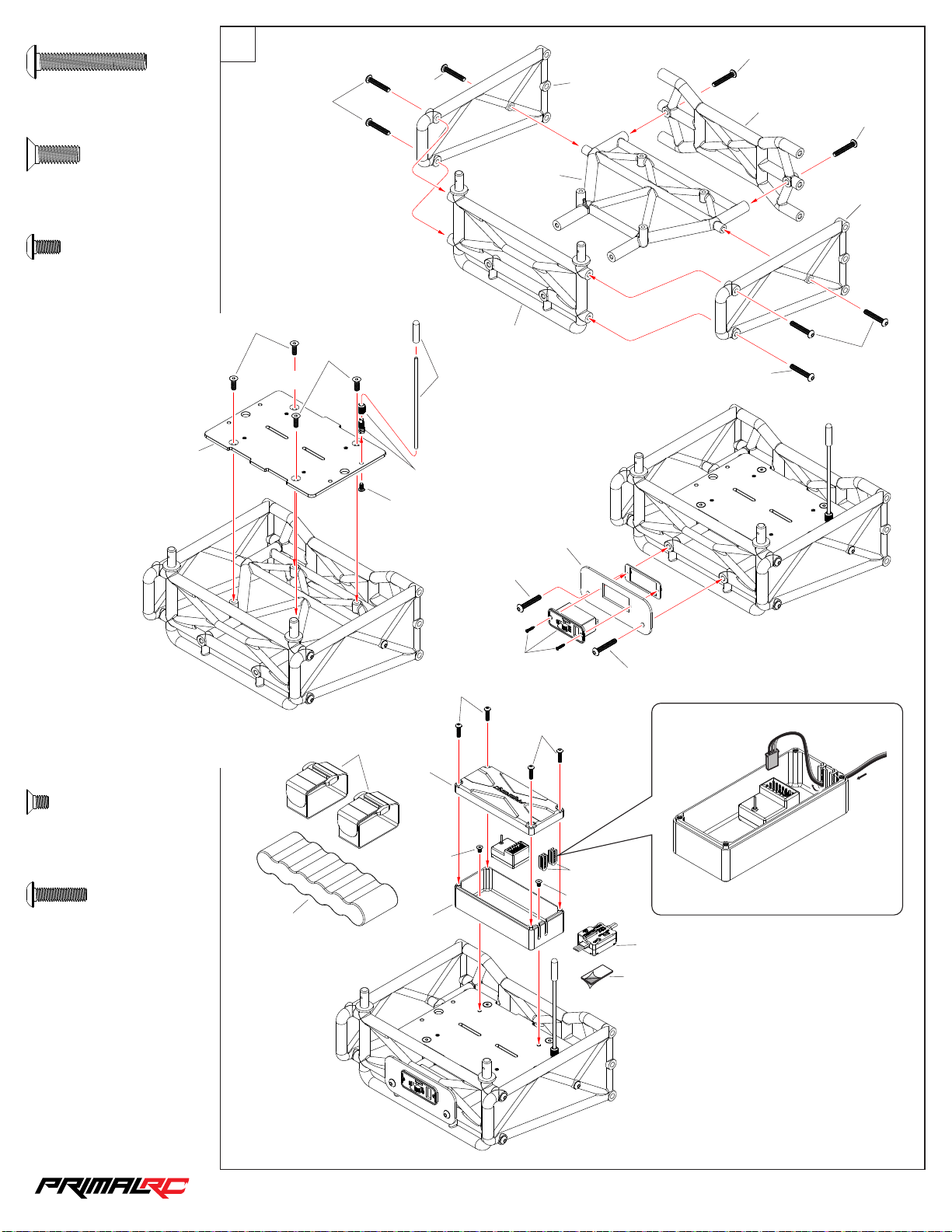
Receiver Assembly
34
49
MBS4 025
MBS4 025
M4×25m m
MFS4 01 2
M4×12m m
MBS3 006
M3×6mm
×10
×4
×1
RMT0 26
MBS4 025
MFS4 01 2
MFS4 01 2
MBS4 025
RMT1 04
MBS3 006
RMT1 05
RMT1 21
RMT1 27
MBS4 025
RMT1 28
RMT1 21
RMT1 27
MBS4 025
MBS4 025
MFS3 00 5
M3×5mm
MBS3 012
M3×12m m
×2
×4
PRE0 06
RMT1 35
MBS4 025
PRE0 08
MBS4 025
MBS3 012
MBS3 012
RMT1 43
RMT0 27
MFS3 00 5
RMT0 27
MFS3 00 5
RMT0 27
PRE0 01
2 Side d Tape
1/5th RAMINATOR MONSTER TRU CK
Page 36
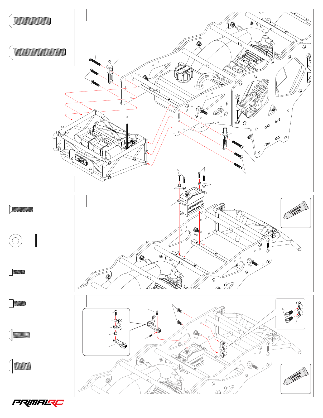
50
35
MBS5 025
M5×25m m
MBS5 035
M5×35m m
×4
×2
MBS5 025
MBS5 035
RMT1 25
MFS3 01 6
RMT1 02
MFS3 01 6
RMT1 25
MBS5 035
MBS5 025
RMT1 02
MFS3 01 6
M3×16m m
MWS0 40 805
Was her 4×8×0.5mm
MCS2 508
M2.5×8 mm
MCS3 008
M3×8mm
MBS4 012
M4×12m m
×4
×1
×1
×1
×1
51
52
MWS0 40 805
MBS4 012
RMT0 28
RMT1 03
RMT0 31
MCS3 008
MCS2 508
PRE0 05
MBS5 012
USE
ALWAYS
RMT0 98
RMT0 33
MBS5 012
M5×12m m
USE
×2
ALWAYS
1/5th RAMINATOR MONSTER TRU CK
Page 37
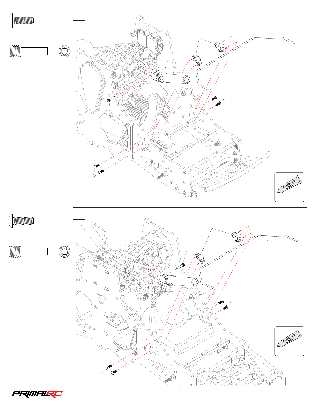
53
36
MBS5 014
M5×14m m
RMT0 55
M8×27m m
×4
×1
MBS5 014
RMT0 55
RMT0 54
RMT0 37
RMT1 40
MBS5 014
USE
MBS5 014
M5×14m m
RMT0 55
M8×27m m
×4
×1
54
RMT0 54
RMT0 55
ALWAYS
RMT0 37
RMT1 40
MBS5 014
USE
ALWAYS
MBS5 014
1/5th RAMINATOR MONSTER TRU CK
Page 38
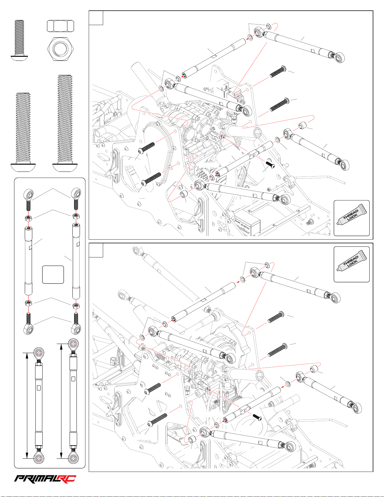
Linkage Assembly
37
×2
55
RMT0 70
M5×20m m
MBS5 020
×4
MBS8 040
RMT0 94
M8×40m m
MNNS 80
×16
RMT0 60
M8 Nut
MNNS 80
RMT0 70
258 mm
258 mm
MBS8 040
MBS8 050
×4
RMT0 71
238 mm
M8×50m m
MBS8 050
MBS8 040
MBS8 050
RMT0 70
RMT0 71
RMT0 61
MBS5 020
238 mm
RMT0 70
USE
ALWAYS
RMT0 47
RMT0 48
×4
MNNS 80
RMT0 94
238 mm
Uppe r link
258 mm
Lowe r link
56
RMT0 70
MBS8 040
MBS8 050
RMT0 70
258 mm
RMT0 60
MBS8 040
258 mm
MBS8 050
RMT0 70
RMT0 61
RMT0 70
MBS5 020
USE
ALWAYS
RMT0 71
238 mm
RMT0 71
238 mm
1/5th RAMINATOR MONSTER TRU CK
Page 39
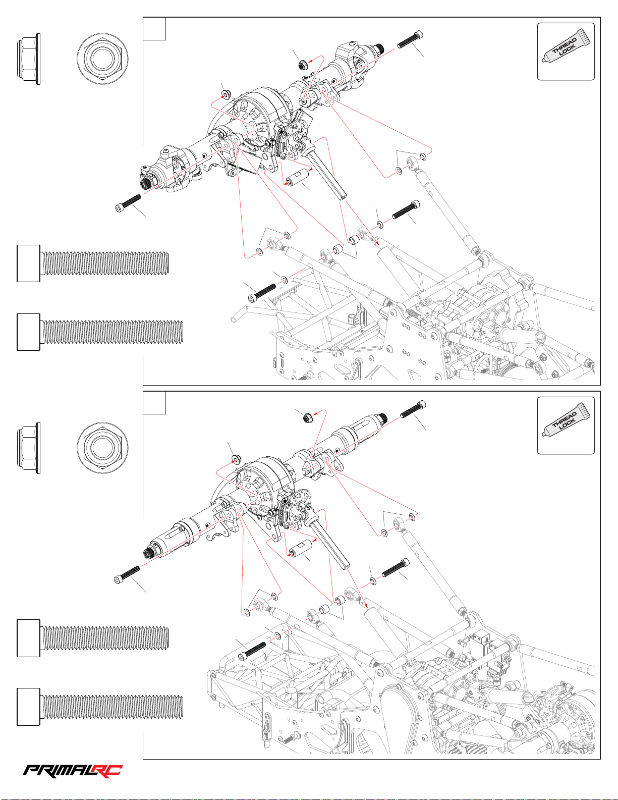
MNS8 0
38
M8 Nyl on Lock Nut
×2
Axle Assembly
57
USE
MNS8 0
MCS8 045
ALWAYS
MNS8 0
RMT0 70
MCS8 045
M8×45m m
MCS8 050
M8×50m m
MNS8 0
M8 Nyl on Lock Nut
×2
×2
×2
MCS8 045
58
MCS8 050
MNS8 0
RMT0 70
RMT0 70
RMT0 45
MNS8 0
RMT0 70
MCS8 050
RMT0 71
USE
MCS8 045
ALWAYS
RMT0 70
MCS8 045
M8×45m m
MCS8 050
M8×50m m
×2
×2
MCS8 045
RMT0 70
RMT0 70
MCS8 050
RMT0 45
RMT0 70
MCS8 050
RMT0 71
1/5th RAMINATOR MONSTER TRU CK
Page 40
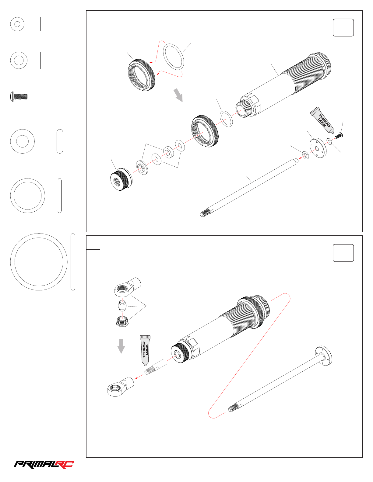
MWS0 30 810
39
Was her 3×8×1mm
×4
Shock Assembly
59
RMT0 74
×4
ORS3 30 25
RMT0 72
MWS0 51 010
Was her 5×10×1mm
MBS3 008
M3×8mm
ORS1 40 35
O-Ri ng D 14×3.5m m
ORS2 00 20
O-Ri ng D 20×2mm
×4
×4
×2
×2
60
RMT0 74
RMT0 75
ORS1 40 35
ORS2 00 20
MWS0 30 810
RMT0 75
MWS0 51 010
MBS3 008
RMT0 72
ORS3 30 25
O-Ri ng D 33×2.5m m
×4
×2
RMT0 76
1/5th RAMINATOR MONSTER TRU CK
Page 41
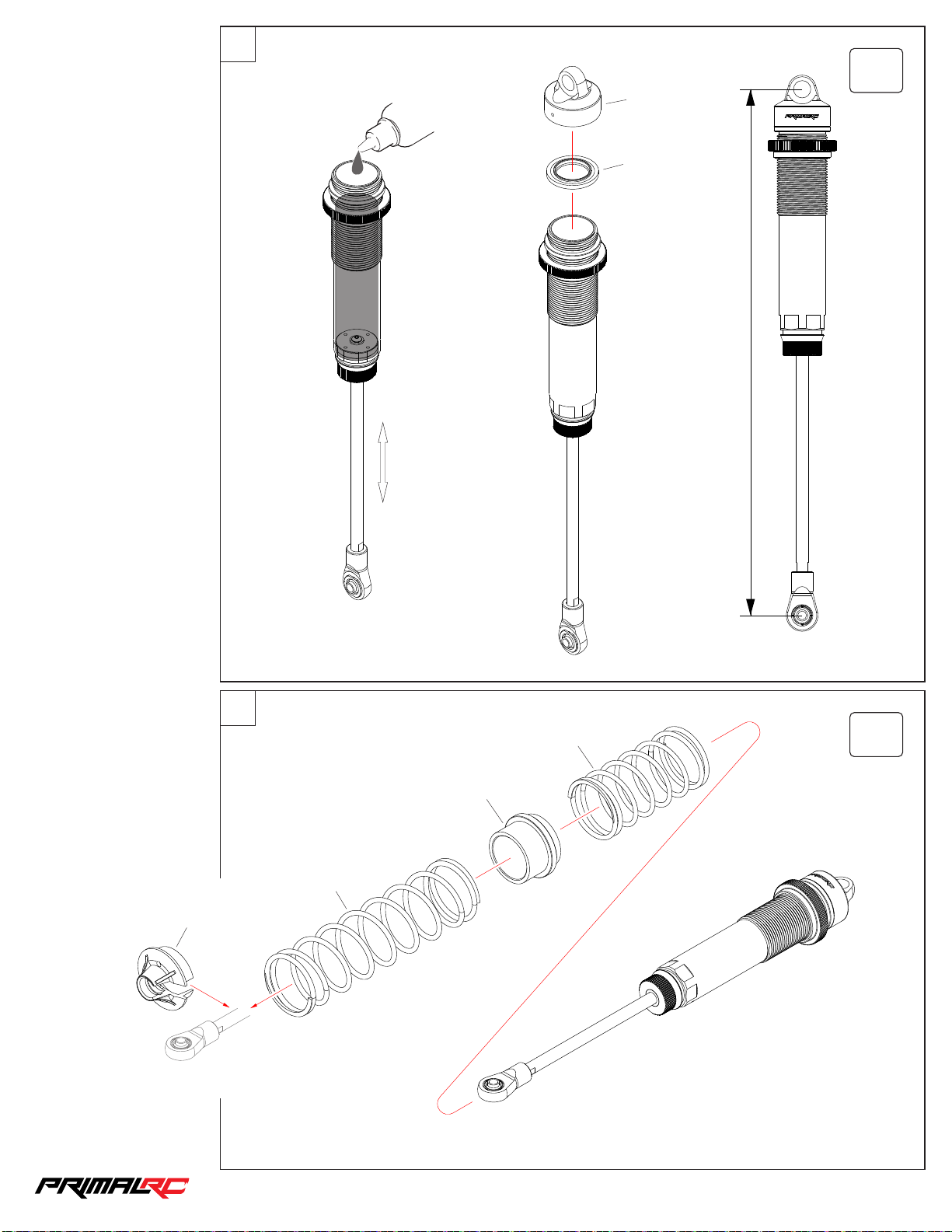
61
40
#100 cst
Shoc k Oi l
×4
RMT0 74
RMT0 40
298.5 mm
RMT0 77
62
RMT1 37
RMT0 75
RMT1 36
×4
1/5th RAMINATOR MONSTER TRU CK
Page 42
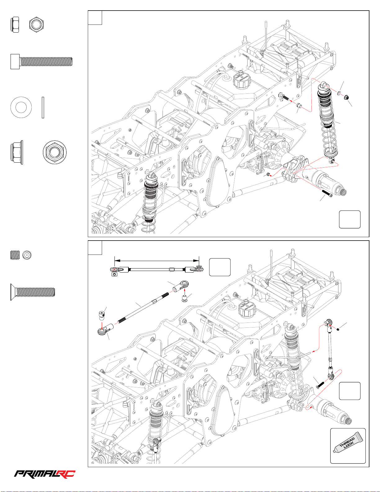
63
41
MNS5 0
M5 Nyl on Lock Nut
MCS5 030
M5×30m m
MWS0 61 212
Was her 6×12×1.2m m
MNS6 0
M6 Nyl on Lock Nut
×4
×4
×4
×4
MWS0 61 212
MNS6 0
RMT0 77
RMT0 79
MNS5 0
MCS5 030
MSS5 005
M5×5mm
MFS5 02 5
M5×25m m
×4
×4
Sway Bar Assembly
64
RMT0 81
RMT1 29
RMT0 82
×4
192. 5 mm
×4
RMT1 29
RMT0 43
MSS5 005
MFS5 02 5
×4
USE
ALWAYS
1/5th RAMINATOR MONSTER TRU CK
Page 43
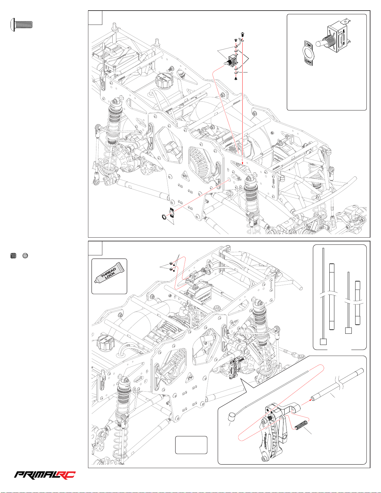
65
42
Engine Kill Switch
MBS4 010
MBS4 010
M4×10m m
×1
PRE0 07
Engine
Kill Switch
To Engin e
Attention: The engine will only
start if the switch toggle is in the
"ON" position"
ALWAYS KEEP THE SWITCH
“ON”!
MSS3 003
M3×3mm
×2
66
USE
ALWAYS
RMT1 01
PRE0 07
MSS3 003
Fron t : 53 0mm
Rear : 1 25 0mm
RMT1 42
RMT1 42
RMT1 42
RMT0 99
F/R
1/5th RAMINATOR MONSTER TRU CK
Page 44
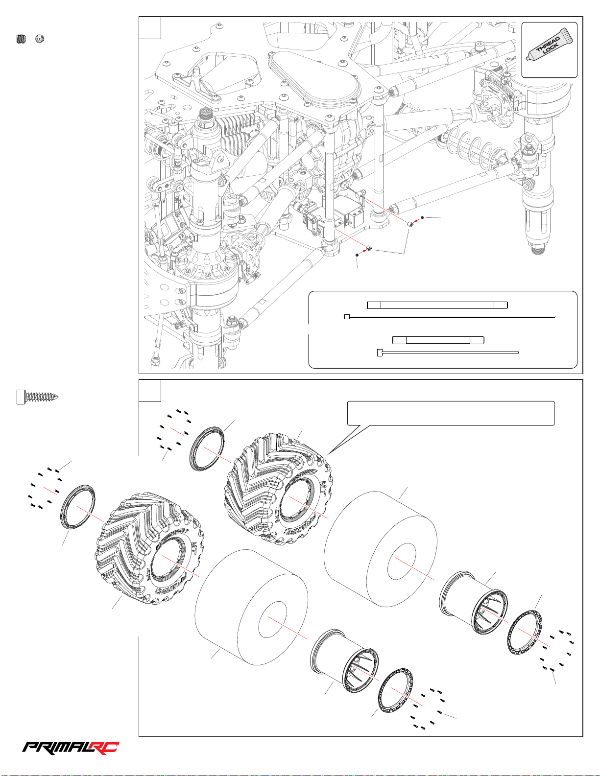
67
43
USE
MSS3 003
M3×3mm
×2
RMT1 41
ALWAYS
MSS3 003
RMT1 01
MSS3 003
Thro tt le wire ro pe : 500m m
TCS3 01 2
ST3×12 mm
RMT113
×2
TCS3 01 2
RMT112
Tire Assembly
68
TCS3 01 2
RMT113
Reve rse wirer ope : 270mm
Asse mble tire s in d ifferen t di rection s to make the m
left s id e and rig ht s ide.
RMT112
RMT112
RMT113
RMT113
RMT112
RMT113
RMT113
TCS3 01 2
TCS3 01 2
1/5th RAMINATOR MONSTER TRU CK
Page 45
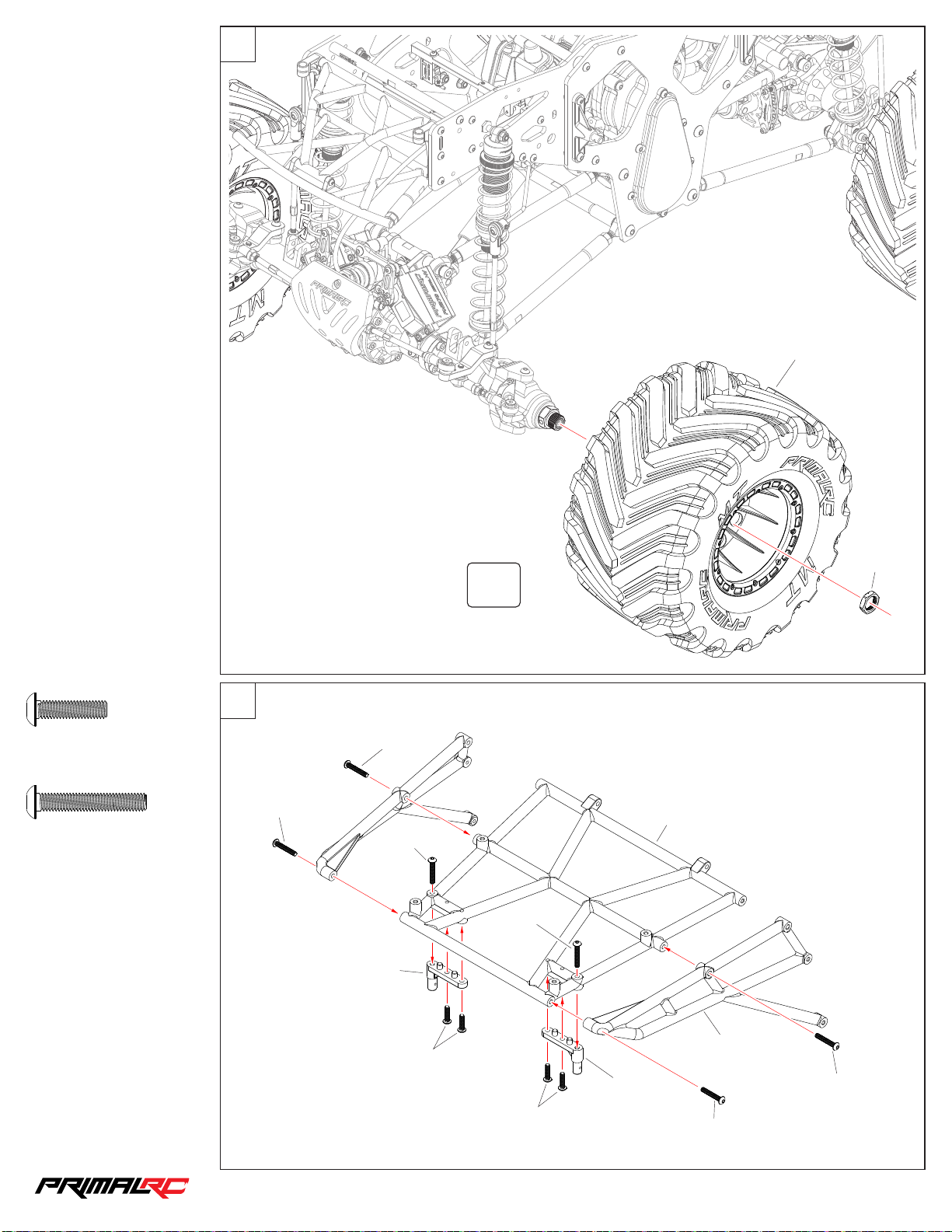
69
44
RMT114
MBS4 016
M4×16m m
MBS4 025
M4×25m m
×4
×6
Roll Cage Assembly
70
MBS4 025
RMT119
RMT1 26
RMT1 00
×4
MBS4 025
RMT118
MBS4 025
MBS4 025
MBS4 016
MBS4 016
RMT119
RMT1 26
MBS4 025
MBS4 025
1/5th RAMINATOR MONSTER TRU CK
Page 46
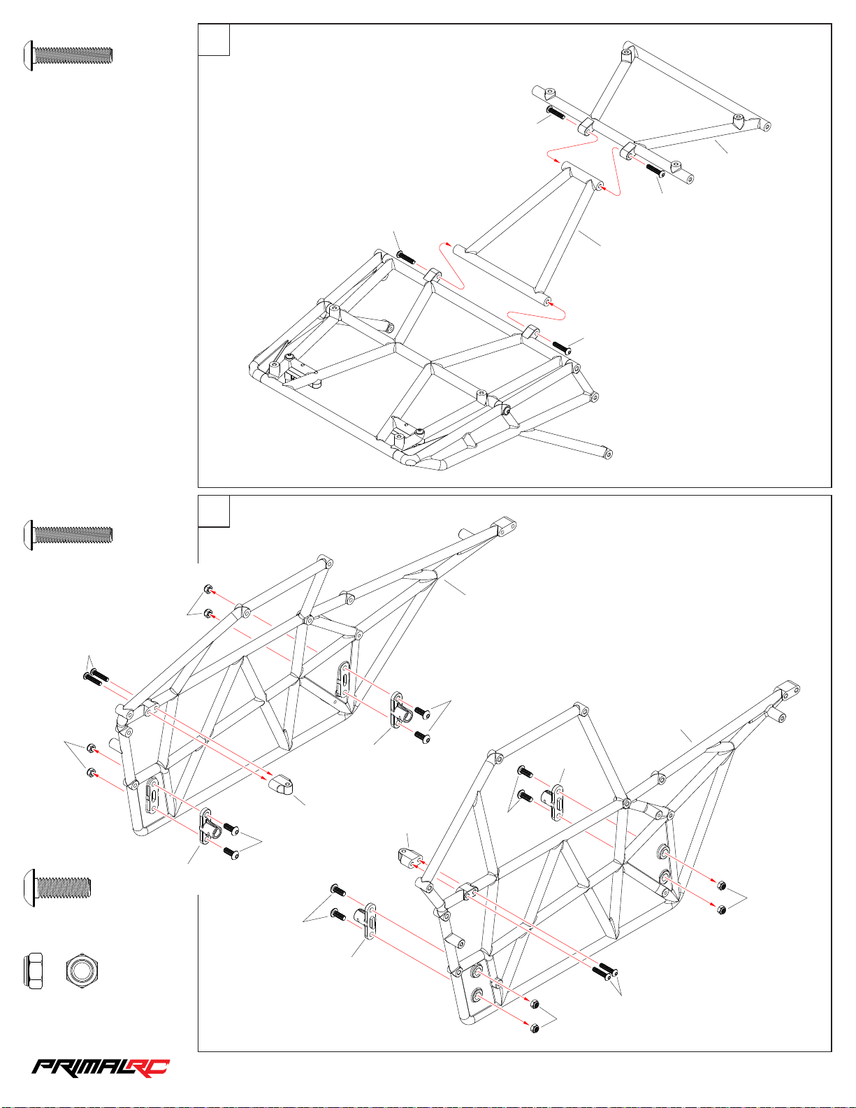
71
45
MBS4 020
M4×20m m
×4
MBS4 020
RMT117
MBS4 020
MBS4 020
RMT118
MBS4 020
MBS4 020
M4×20m m
MBS4 020
MNS5 0
MBS5 014
M5×14m m
×4
×8
MNS5 0
RMT1 24
72
RMT1 24
MBS5 014
MBS5 014
RMT1 24
RMT1 24
RMT1 20
MBS5 014
RMT1 20
RMT1 24
MBS5 014
MNS5 0
MNS5 0
M5 Nyl on Lock Nut
×8
RMT1 24
MBS4 020
MNS5 0
1/5th RAMINATOR MONSTER TRU CK
Page 47
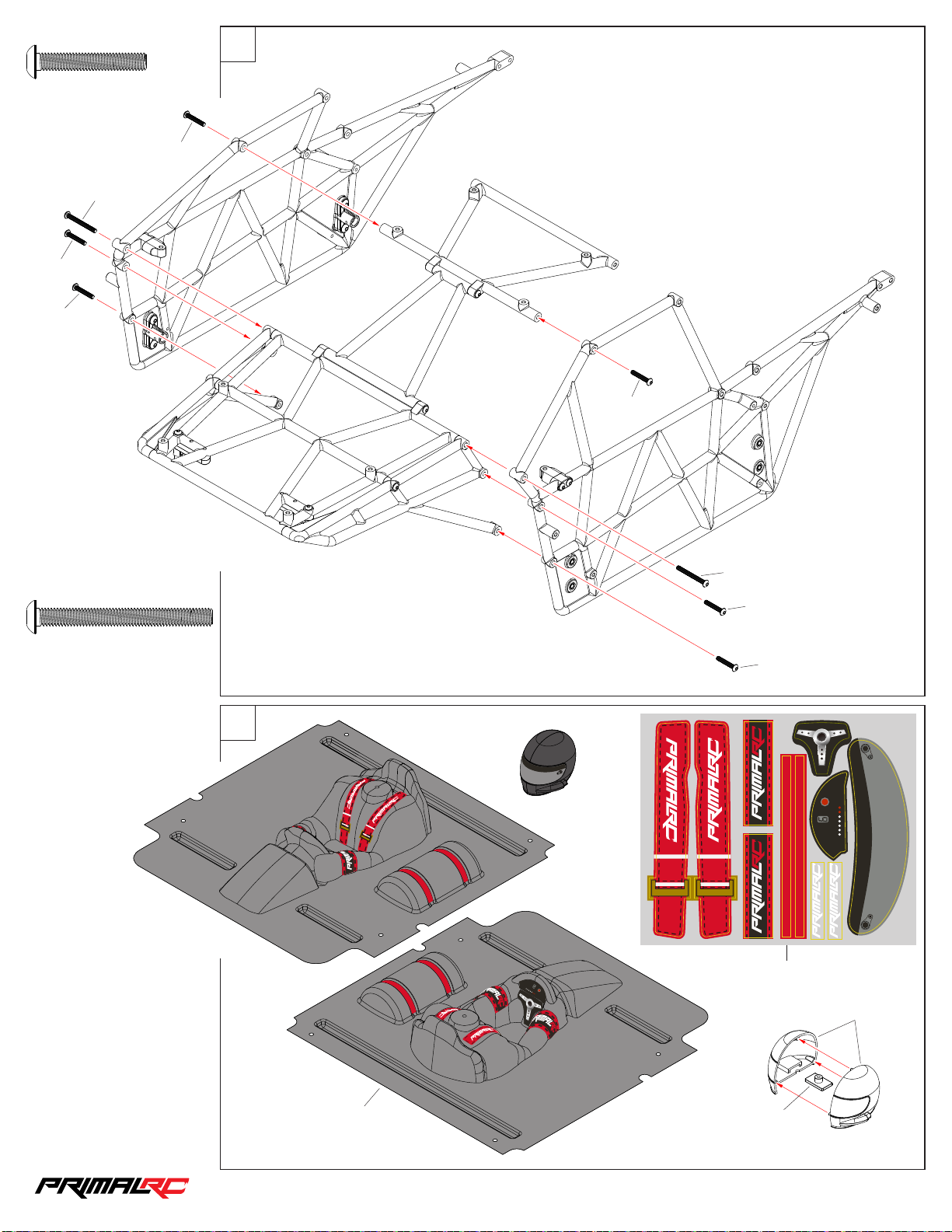
73
46
MBS4 025
M4×25m m
MBS4 040
MBS4 025
MBS4 025
×6
MBS4 025
MBS4 025
MBS4 040
M4×40m m
×2
MBS4 040
MBS4 025
MBS4 025
74
RMT1 33
RMT1 33
RMT1 33
RMT1 33
1/5th RAMINATOR MONSTER TRU CK
Page 48
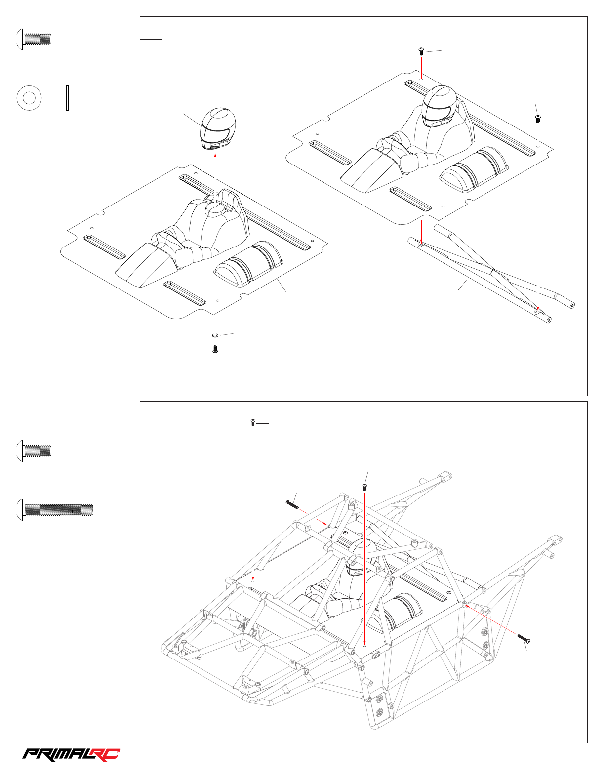
MBS4 010
47
M4×10m m
75
MBS4 010
×3
MWS0 40 805
Was her 4×8×0.5mm
×1
RMT1 33
RMT1 33
MWS0 40 805
MBS4 010
MBS4 010
RMT1 23
MBS4 010
M4×10m m
MBS4 025
M4×25m m
76
MBS4 010
MBS4 010
×2
MBS4 025
×2
MBS4 025
1/5th RAMINATOR MONSTER TRU CK
Page 49
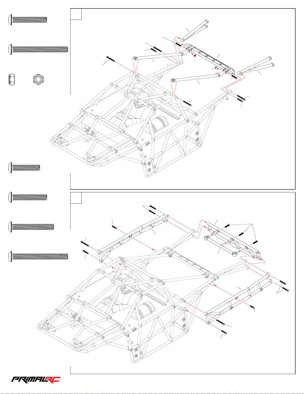
77
48
MBS4 025
M4×25m m
MBS4 040
M4×40m m
MNS4 0
M4 Nyl on Lock Nut
×4
×4
×2
MBS4 040
MBS4 040
MBS4 025
MBS4 025
RMT119
RMT1 20
MNS4 0
MBS4 040
RMT1 22
MNS4 0
RMT1 20
MBS4 025
RMT119
MBS4 040
MBS4 025
MBS4 020
M4×20m m
MBS4 025
M4×25m m
MBS4 030
M4×30m m
MBS4 040
M4×40m m
×5
×2
×4
×2
78
MBS4 040
MBS4 025
MBS4 020
MBS4 030
RMT1 23
MBS4 020
RMT1 21
RMT1 22
RMT1 21
MBS4 030
MBS4 020
MBS4 040
MBS4 025
1/5th RAMINATOR MONSTER TRU CK
Page 50
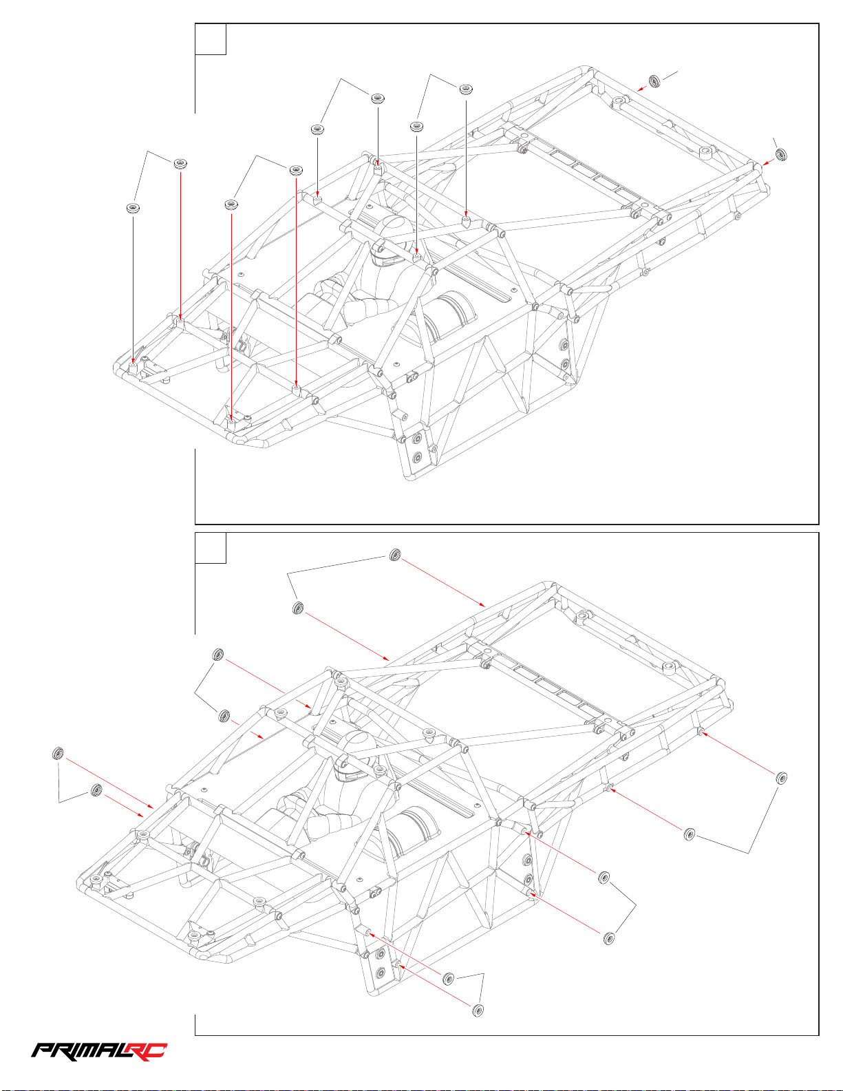
79
49
RMT1 30
RMT1 30
RMT1 30
RMT1 30
RMT1 30
RMT1 30
RMT1 30
80
RMT1 30
RMT1 30
RMT1 30
RMT1 30
RMT1 30
1/5th RAMINATOR MONSTER TRU CK
Page 51
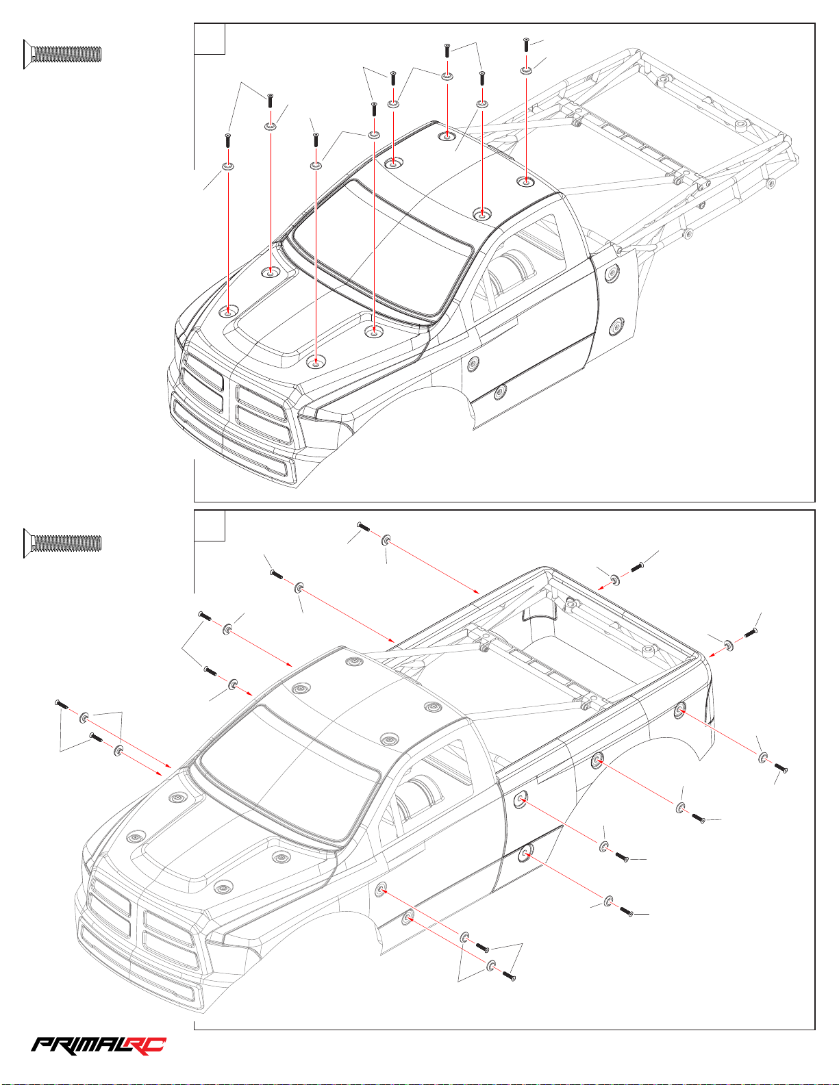
MFS4 02 0
50
M4×20m m
×8
81
RMT1 30
Body Assembly
MFS4 02 0
RMT1 30
MFS4 02 0
MFS4 02 0
RMT1 30
RMT1 30
MFS4 02 0
RMT1 30
MFS4 02 0
RMT1 30
MFS4 02 0
M4×20m m
MFS4 02 0
×14
MFS4 02 0
RMT1 30
82
RMT1 30
MFS4 02 0
RMT1 30
RMT1 30
MFS4 02 0
RMT1 30
RMT1 30
MFS4 02 0
RMT1 30
RMT1 30
MFS4 02 0
RMT1 30
MFS4 02 0
MFS4 02 0
MFS4 02 0
RMT1 30
RMT1 30
MFS4 02 0
MFS4 02 0
RMT1 30
1/5th RAMINATOR MONSTER TRU CK
Page 52

83
51
RMT1 50
Body C lip 8mm
×10
RMT1 50
RMT1 50
RMT1 50
RMT1 50
RMT1 50
RMT1 50
RMT1 50
RMT1 50
1/5th RAMINATOR MONSTER TRU CK
Page 53

Parts list
52
Part N o. D escri pt ion Part N o. D escri pt ion Part No . De scrip ti on
RMT001 Diffe re nt ia l ca se
RMT002 Solid axle set
RMT003 Front hub carriers
RMT004 Steering block
RMT005 Rear hubs
RMT006 Link mounts
RMT007 Front link mounts
RMT008 Rear link mounts
RMT009 Servo saver set
RMT010 Chain box
RMT011 Gear box
RMT012 Gear box cover set
RMT013 Shift fork
RMT014 Engine mounts
RMT015 Steering servo mounts
RMT016 Servo saver mounts
RMT017 Steering link
RMT018 Servo arm set
RMT019 Steering link mounts
RMT020 Left main frame
RMT021 Right main frame
RMT022 Frame
RMT023 Frame mounts set
RMT024 Tank mounts
RMT025 Servo link
RMT026 Receiver box mounts
RMT027 Receiver box set
RMT028 Brake wirerope seat
RMT029 Throttle wirerope seat
RMT030 Servo arm 22mm(25T)
RMT031 Servo arm 28mm(15T)
RMT032 Throttle servo mounts
RMT033 Brake wirerope mounts
RMT034 Brake disk pad mounts
RMT035 Diffe re nt ia l ho us in g
RMT036 Brake disk rotor
RMT037 Sway bar mount
RMT038 Bumper
RMT039 Servo saver set
RMT040 Shock diaphragm
RMT041 Steering post
RMT042 Spacer 16mm
RMT043 11mm B al l
RMT044 King pin bushing
RMT045 Upper link mount
RMT046 24mm Wheel hex hub
RMT047 Upper link 180mm
RMT048 Lower link 200mm
RMT049 6×45mm Turnbuckle
RMT050 6×125mm Turnbuckle
RMT051 Diff ax le s ha ft
RMT052 Universal drive shaft set
RMT053 Straight axle shaft
RMT054 Drive shaft
RMT055 Shaft screw
RMT056 Sprocket shaft
RMT057 Clutch bell
RMT058 Link 198mm
RMT059 Link 224mm
RMT060 Link 190mm
RMT061 Link 170mm
RMT062 Operate screw
RMT063 Gear Hex mount
RMT064 Gear box synchronizer
RMT065 Synchronizer shaft
RMT066 Gear box rear shaft
RMT067 Gear box front shaft
RMT068 Wirerope mounts
RMT069 Shift fork shaft
RMT070 Spacer M8×2.5mm
RMT071 Spacer M8×12.5mm
RMT072 Shock shaft
RMT073 Shock body
RMT074 External shock parts set
RMT075 Inside shock parts set
RMT076 Shock ball end set
RMT077 Shock parts set
RMT078 Shock stand off
RMT079 Shock completed set
RMT080 Spacer M6
RMT081 11mm B al l
RMT082 6×159mm Turnbuckle
RMT083 Sprocket 10T
RMT084 Sprocket 30T
RMT085 Spiral bevel gear 15T
RMT086 Spiral bevel gear 45T
RMT087 Spiral bevel gear 17T
RMT088 Spiral bevel gear 34T
RMT089 Drive gear 20T
RMT090 Drive gear 20T/30T
RMT091 Drive gear 23T/27T
RMT092 Drive gear 25T
RMT093 Chain
RMT094 Joint bearing M8
RMT095 Brake disk pad
RMT096 Brake arm
RMT097 Brake shaft
RMT098 Wirerope screw
RMT099 Brake spring set
RMT100 24mm Wheel nut
RMT101 Stop collar
RMT102 Spacer M3
RMT103 Servo bushing
RMT104 Antenna pipe mount
RMT105 Antenna pipe set
RMT106 Diffe re nt ia l sh af t
RMT107 Diffe re nt ia l ge ar s et
RMT108 Inner diff Washer set
RMT109 Diffe re nt ia l co mp le te d se t
RMT110 Joint bearing
RMT111 Reverse joint bearing
RMT112 MT ti re w it h in ne r fo am
RMT113 MT wh ee l hu b
RMT114 MT wh ee l co mp le te d se t
RMT115 Tank set
RMT116 Rubber bushing
RMT117 Top roll cage
RMT118 Front roll cage
RMT119 Front auxiliary roll cage
RMT120 Left/Right roll cage set
RMT121 Left/Right auxiliary roll cage
RMT122 Central roll cage mount
RMT123 Rear roll cage
RMT124 Painted cockpit mount set
RMT125 Front roll cage mount set
RMT126 Left/Right roll cage mount set
RMT127 Rear bumper
RMT128 Rear bumper strengthen
RMT129 Steering ball end set
RMT130 Body stator set
RMT131 Body with sticker(Red)
RMT132 Body with sticker(Clear)
RMT133 Painted cockpit(Black)
RMT134 Cockpit(Clear)
RMT135 Switch mounts
RMT136 Shock spring D38×110 mm
RMT137 Shock spring D38×150mm
RMT138 Servo spring
RMT139 Gear box spring
RMT140 Sway bar set
RMT141 Servo wirerope set
RMT142 Brake wirerope set
RMT143 Battery strap 20×200mm
RMT144 Nylon braided tube
RMT145 Diffe re nt ia l Pa d
RMT146 Engine 49CC
RMT147 Air filter set
RMT148 Exhaust pipe set
RMT149 Exhaust gasket
RMT150 Body clip 8mm
RMT151 Shock diaphragm
PRE001 Fail safe engine breaker
PRE002 GT5 Transmitter with receiver
PRE003 GT5 receiver
PRE004 No.712 Servo
PRE005 PM1373 Servo
PRE006 Battery pack for receiver
PRE007 Engine switch
PRE008 Harness for servo
ORS14020 O-ring D14×2
ORS14035 O-ring D14×3.5
ORS20020 O-ring D20×2
ORS22025 O-ring D22×2.5
ORS33025 O-ring D33×2.5
BBS101504 Bearing 10×15×4
BBS050825 Bearing 5×8×25
BBS092006 Bearing 9×20×6
BBS101905 Bearing 10×19×5
BBS102206 Bearing 10×22×6
BBS122406 Bearing 12×24×6
BBS152807 Bearing 15×28×7
FBS152807 Flanged bearing 15×28×7
BBS203207 Bearing 20×32×7
FBS203207 Flanged bearing 20×32×7
PINS5024 Pin 5×24mm
MCDS12 Shaft ring 12mm
TCS3012 M 3× 12 Tp. Cap head screw
MBS3006 M3×6 Button head screw
MBS3008 M3×8 B ut to n he ad s cr ew
MBS3012 M3×1 2 Bu tt on h ea d sc re w
MBS4010 M4×1 0 Bu tt on h ea d sc re w
MBS4012 M4×1 2 Bu tt on h ea d sc re w
MBS4016 M4×1 6 Bu tt on h ea d sc re w
MBS4020 M4×2 0 Bu tt on h ea d sc re w
MBS4025 M4×2 5 Bu tt on h ea d sc re w
MBS4030 M4×3 0 Bu tt on h ea d sc re w
MBS4040 M4×4 0 Bu tt on h ea d sc re w
MBS5012 M5×1 2 Bu tt on h ea d sc re w
MBS5014 M5×1 4 Bu tt on h ea d sc re w
MBS5016 M5×1 6 Bu tt on h ea d sc re w
MBS5020 M5×2 0 Bu tt on h ea d sc re w
MBS5025 M5×25 Button head screw
MBS5030 M5×3 0 Bu tt on h ea d sc re w
MBS5035 M5×35 Button head screw
MBS6010 M6×10 Button head screw
MBS6016 M6×16 Button head screw
MBS6020 M6×20 Button head screw
MBS6025 M6×25 Button head screw
MBS6030 M6×30 Button head screw
MBS6035 M6×35 Button head screw
MBS6040 M6×40 Button head screw
MBS6065 M6×65 Button head screw
MBS8040 M8×40 Button head screw
MBS8050 M8×5 0 Bu tt on h ea d sc re w
MCS2508 M2.5×8 Cap head screw
MCS3008 M3×8 Cap head screw
MCS3012 M3×12 Cap head screw
MCS3020 M3×20 Cap head screw
MCS4020 M4×20 Cap head screw
MCS5010 M5×10 Cap head screw
MCS5012 M5×12 Cap head screw
MCS5014 M5×14 Cap head screw
MCS5016 M5×16 Cap head screw
MCS5020 M5×20 Cap head screw
MCS5025 M5×25 Cap head screw
MCS5030 M5×30 Cap head screw
MCS5040 M5×40 Cap head screw
MCS6020 M6×20 Cap head screw
MCS8045 M8×45 Cap head screw
MCS8050 M8×50 Cap head screw
MFS3005 M3× 5 Fl at h ea d sc re w
MFS3010 M3× 10 F la t he ad s cr ew
MFS3014 M3× 14 F la t he ad s cr ew
MFS3016 M3× 16 F la t he ad s cr ew
MFS4012 M4× 12 F la t he ad s cr ew
MFS4020 M4× 20 F la t he ad s cr ew
MFS5016 M5× 16 F la t he ad s cr ew
MFS5025 M5× 25 F la t he ad s cr ew
MFS6016 M6× 16 F la t he ad s cr ew
MFS6020 M6× 20 F la t he ad s cr ew
MFS6025 M6× 25 F la t he ad s cr ew
MES40 E-clip 4mm
MES70 E-clip 7mm
MNS40 M4 Nylon nut
MNS50 M5 Nylon nut
MNNS60 M 6 Nu t
MNRS60 M 6 Re ve rs e nu t
MNFS60 M6 Flanged nylon nut
MNFS80 M8 Flanged nylon nut
MNNS80 M 8 Nu t
MSS3003 M3×3 Set screw
MSS4004 M4×4 Set screw
MSS5005 M5×5 Set screw
MPS50 Spring washer M5
MPS60 Spring washer M6
MWS030810 Was he r 3× 8× 1
MWS040805 Was he r 4× 8× 0. 5
MWS051010 Was he r 5× 10 ×1
MWS061212 Was he r 6× 12 ×1 .2
MWS061612 Was he r 6× 16 ×1 .2
MWS101510 Was he r 10 ×1 5× 1
MWS202810 Was he r 20 ×2 8× 1
1/5th RAMINATOR MONSTER TRU CK
Page 54

Copyright Primal RC 2019
 Loading...