

Page 1
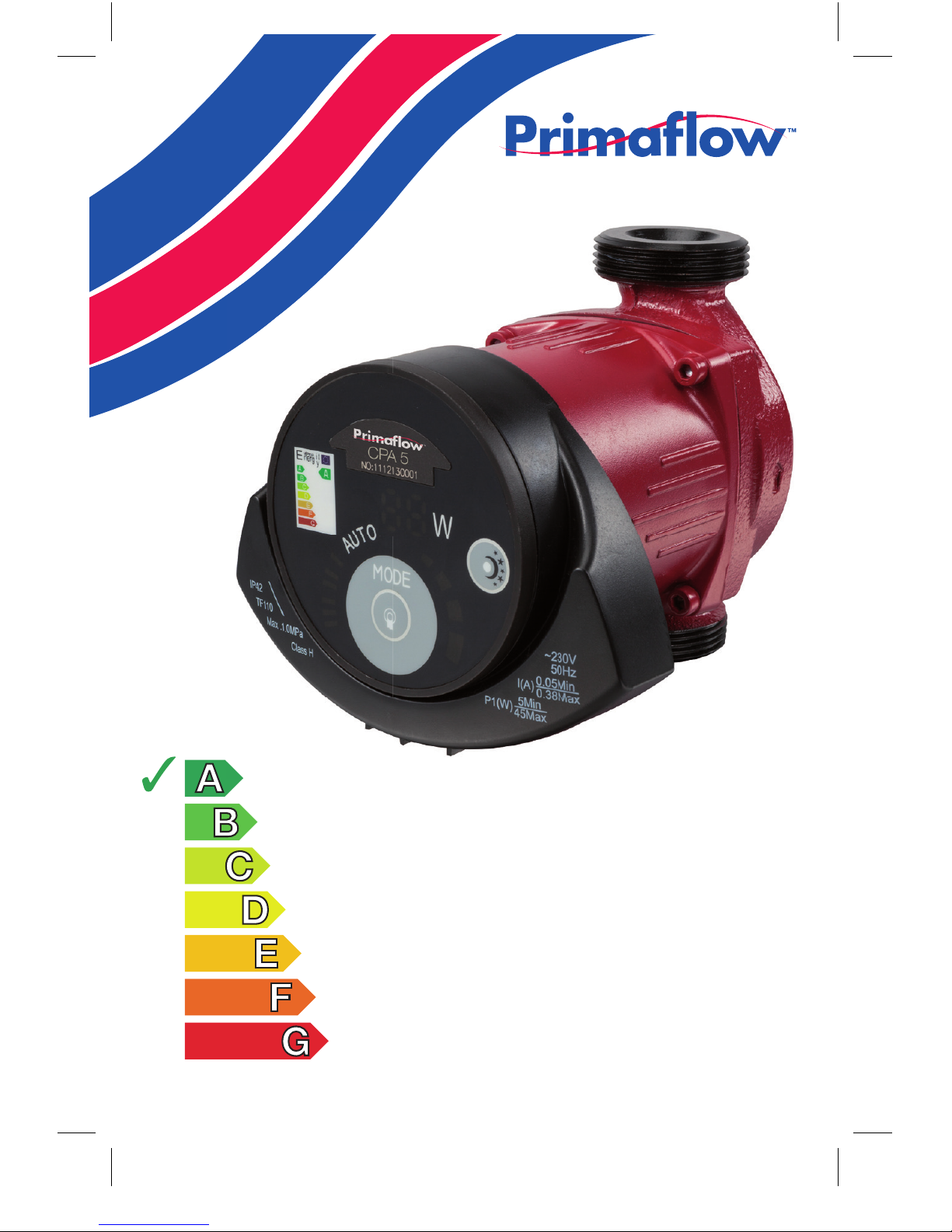
EuP compliant high
effi ciency heating
circulation pump
Installation, operation
and maintenance guide
Page 2

2
Contents
1. Important information 3
2. Overview 4
3. Operating environment 5
4. Installation 6
5. Electrical connection 8
6. Control panel 9
7. Pump settings 10
8. Night mode 11
9. Use with a bypass valve 11
10. Commissioning 12
11. Settings and pump performance 13
12. Features 16
13. Technical specifications 17
14. Dimensions 18
15. Troubleshooting 18
16. Warranty 19
Page 3

3
1. Important information
Please read before installing pump
• Primaflow will not be liable for damage or injury if the guidelines presented
in this booklet are not complied with in all respects
• It is the responsibility of the installer to ensure that any local building
regulations relating to the installation of this pump are fully complied with
• The pump must be installed by a competent person properly qualified to
carry out such work
• The installer is responsible for advising the end user how the pump should
be maintained with reference to this booklet. Failure to maintain the pump
properly in accordance with these guidelines will invalidate the warranty
• The electrical supply must be isolated prior to installation and maintenance
of the pump
• The pump must not be installed
- in places subject to high humidity or near open sources of water
- in poorly ventilated areas where condensation can occur causing
potential damage to electrical components
- outside or otherwise exposed to the elements
• The pump should be installed with service valves either side of the unit to
facilitate maintenance
• The pump warranty will be invalid if the heating system is not protected
with a suitable corrosion inhibitor
• The pump should not be operated without water in the system and should
be primed with water by opening the service valves prior to switching on
the electrical supply. Warranty will be invalid if a pump has been run dry
• To avoid burns and scalding the central heating system must be switched
off and allowed to cool prior to any servicing of the pump
• To avoid frost damage the pump should be completely drained of water
when exposed to a risk of freezing
• During long periods without use the electrical supply to the pump should
be isolated and the service valves closed
• Any damaged cables must be replaced by a competent person
• In case of malfunction the pump should be isolated from the electrical
supply and a competent heating engineer should be summoned
• The pump should be installed beyond the reach of small children
• This pump is not suitable for domestic drinking water
Page 4

4
2. Overview
Primaflow CPA series pumps are designed to circulate hot water
around a domestic heating system and are suitable for
• Constant and variable flow
• Variable temperatures
• Systems with night mode requirements
These pumps use a permanent magnet motor and differential pressure
controller that monitors and adjusts the pump performance to meet
the system demands. The control panel allows the user to override the
automatic settings to the desired performance levels if required.
Primaflow CPA series pumps offer
• Easy installation and start up: the Auto setting allows the pump to be
installed, bled and set to the desired performance level of the system
without any adjustment by the installer
•
Low power consumption: the pump complies with EC directive 641/2009
• Low noise
• 2 year warranty: subject to the return of the enclosed warranty
card, see section 16
Page 5

5
3. Operating environment
The CPA series pump is suitable for the following operating environment
• Ambient temperature: 0°C to +40°C
• Maximum relative humidity: 95%
• Water temperature range: +2°C to +110°C
• Maximum pressure: 10 bar
• Protection grade: IP42
Outside of these conditions a premature failure may be anticipated
and the warranty will be invalid.
In order to prevent condensation forming within the control box the
water temperature in the pump must always be higher than the ambient
temperature in the vicinity of the pump, see page 17.
To avoid cavitation corrosion within the pump the inlet pressure must
be kept as low as possible. Recommended pressures at different
temperatures are listed below:
Water temp <75°C 90°C 110° C
Inlet pressure 0.05 bar 0.3 bar 1 bar
The water within the system and the pump must be:
• Clean
• Non-corrosive
• Protected with a suitable corrosion inhibitor
• Non-viscous
• Free from solids and particles
Primaflow CPA pumps are not suitable for use with flammable liquids such
as oil and petrol. Use of pumps for viscous liquids will lead to high power
consumption and reduced service life.
Page 6
6
4. Installation
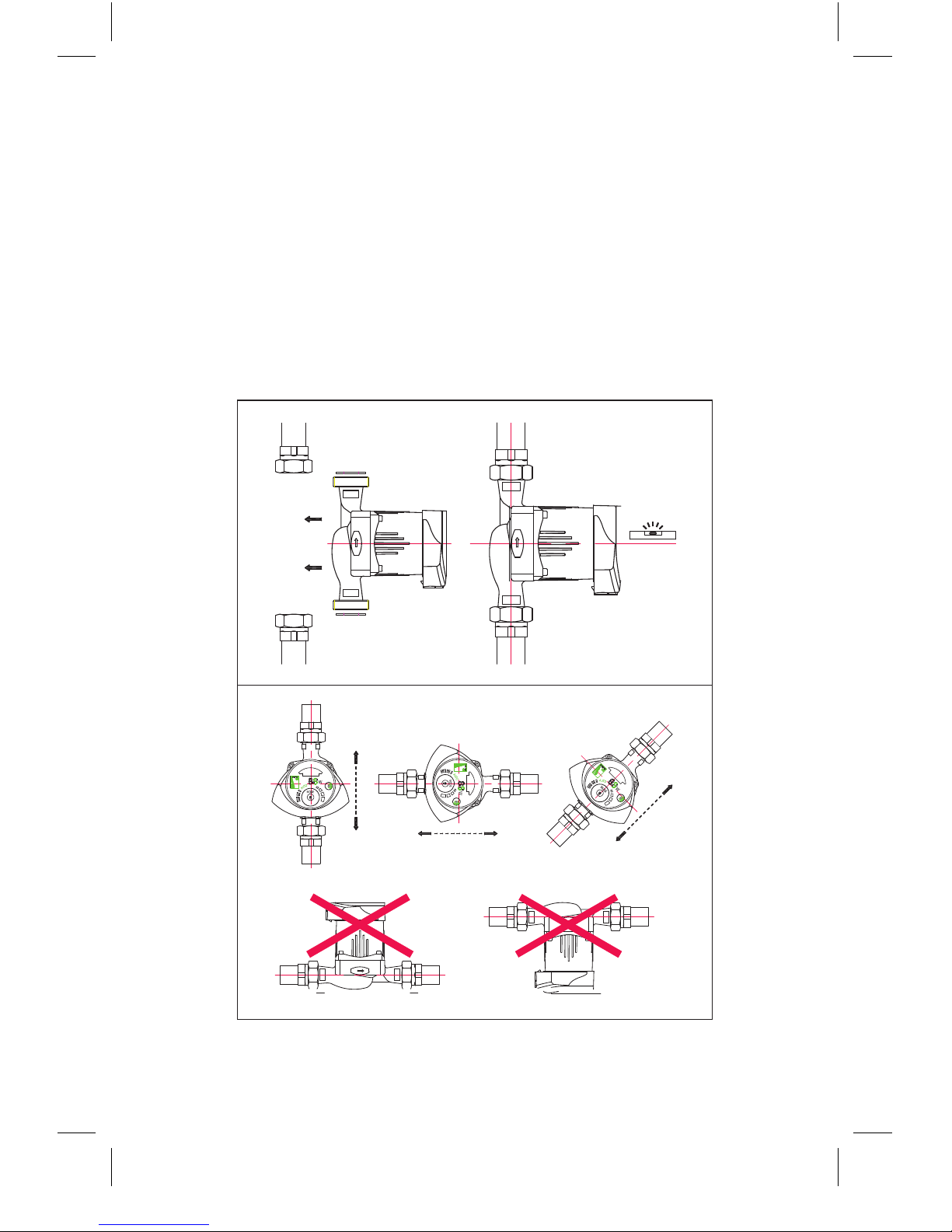
4.1 The pump shaft must be horizontal when installed as shown in the
images below. Flow will be in the direction of the arrow shown on the
pump body.
• Position the pump between 2 service valves and assemble with gaskets
• Hand tighten the union nuts ensuring that the pump is in the correct
orientation for the shaft, control panel and direction of flow. Realign if
required. The control panel can be adjusted as described in section 4.2
• Tighten the union nuts ensuring a watertight seal has been made
• Connect the electrical supply as described in section 5
Page 7
7
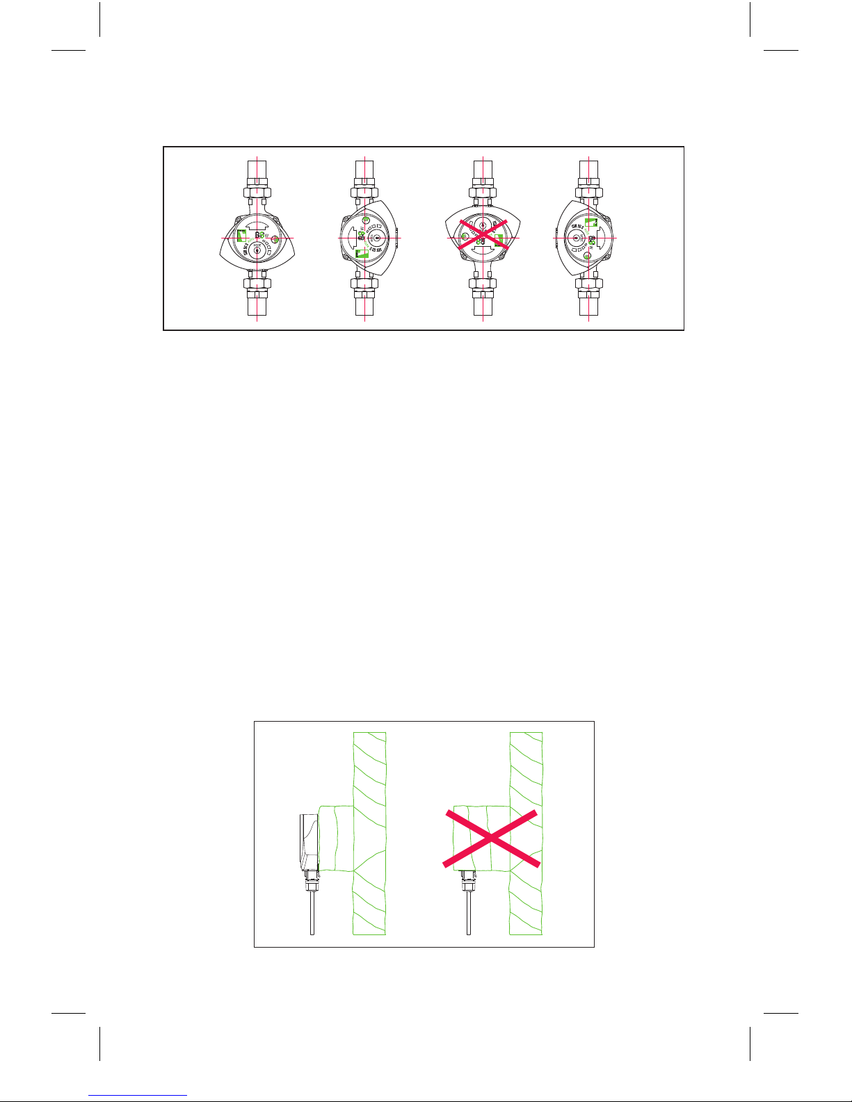
4.2 The control panel can be oriented in 3 of the 4 positions shown below.
The panel can be adjusted to suit the requirement of the installation.
In order to do this the control panel can rotate through 90° as follows:
• If already installed
- Isolate the electrical supply and allow the pump and system to cool
- Close the service valves on either side of the pump
- Disconnect the cable from the control panel
Then follow instructions below
• Loosen and remove the 4 hexagonal screws attaching the pump body
to its base.
WARNING – there will be some water leakage if the pump has
been used
• Rotate the motor and control panel to the required position
• Replace the 4 hexagonal screws and tighten
In order to reduce heat loss through the pump it can be insulated as
shown in the diagram below. WARNING - do not cover the control panel
or electric connections.
Page 8
8
5. Electrical connection
WARNING:
• Electrical connection must be carried out only by a competent
person and the pump must be fitted in compliance with current
electrical regulations
• Supply voltage and frequency must match those shown on
the control panel
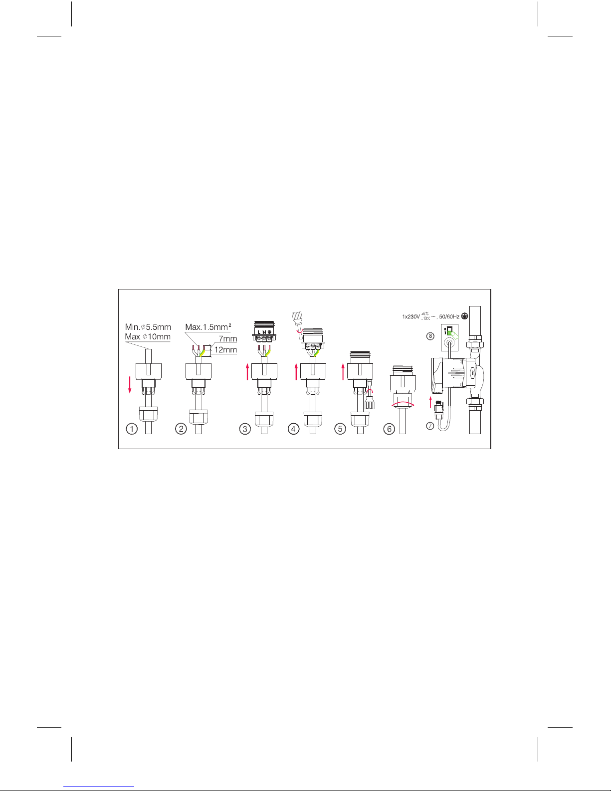
• The pump must be connected to the electrical supply using
the connector provided
• The control panel light will indicate when connected to the
power supply
Connect the pump to the electrical supply in the following sequence
Open the service valves to allow water into the pump before switching on
the electrical supply. Failure to do so may damage the pump reducing it’s
life and invalidating the warranty.
Page 9
9
6. Control panel
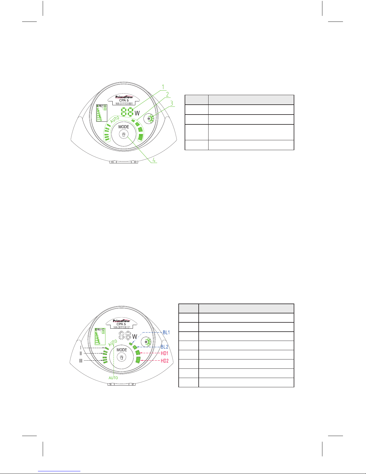
The control panel and functions are as follows
1. Power consumption: When the pump is operating the power being
consumed by the pump will be displayed. The power consumption will
vary depending on the pump setting and the demand of the system.
If the display shows “E” refer to the troubleshooting guide on page 18.
2. Pump mode: Press the mode button to advance the setting one step.
Press eight times (with a 2 second gap) to cycle the pump through the
range of settings
3. Night mode: This function is available only if there is a night mode
setting on the boiler. Press the button to toggle night mode on and off
as indicated by the light.
NOTE: If the pump is set to Auto the night mode does not need to be activated.
If the pump is set on speeds I, II or III the night mode must NOT be switched on.
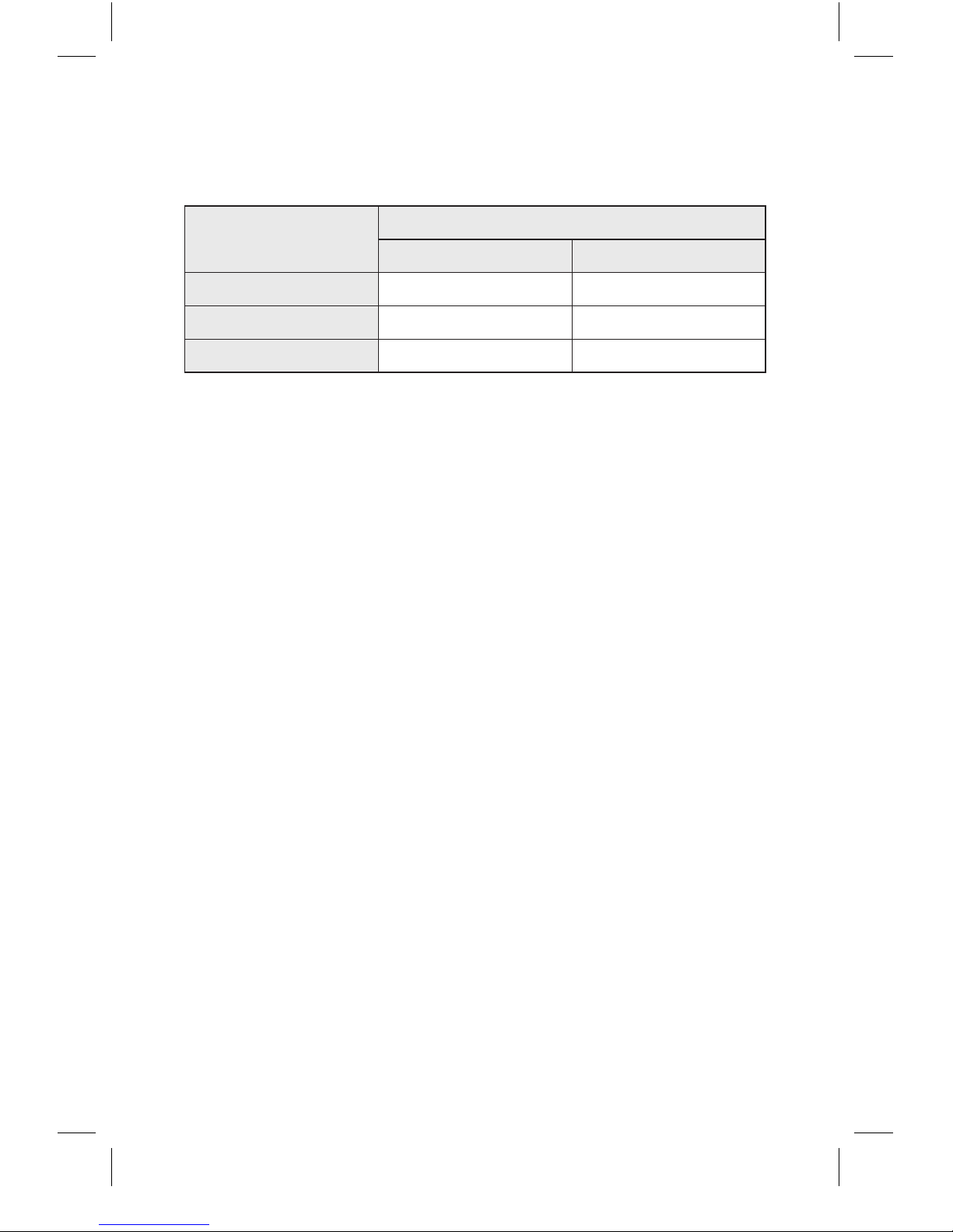
4. Pump settings: There are 8 settings as described below which
can be selected by sequentially pressing the pump mode button.
Label Description
1 Power consumption (W)
2 Pump mode indicator dial
3 Night mode button
and indicator
4 Pump mode button
Label Description
Auto
Fully automatic for optimum efficiency
BL1
Lowest proportional pressure curve
BL2
Highest proportional pressure curve
HD1 Lowest constant pressure curve
HD2 Highest constant pressure curve
III Highest constant speed curve
II Medium constant speed curve
I Lowest constant speed curve
Page 10
10
7. Pump settings
The pump should be set according to the type of heating system.
System type
Pump settings
Recommended Alternative
Underfloor Auto HD1 / HD2
Two pip e Auto BL2
Single pipe BL1 BL2
Auto mode automatically adjusts the pump performance according to
the heating system demands. It is recommended the pump is set to Auto
when initially installed. If the desired performance is not achieved then
manual adjustment to the other settings can be considered.
Depending on the heat demand by the system the pump will adjust the
power requirements according to proportional pressure control (BL) or
constant pressure control curves (HD).
• Proportional Pressure Control: In this mode the pressure difference
across the pump is determined by the flow and is indicated by curves
BL1 and BL2 in the Q/H diagram shown in chapter 11
• Constant Pressure Control: In this mode the pressure difference
across the pump is constant regardless of the flow conditions within
the system and is indicated by HD1 and HD2 in the Q/H Diagram
shown in chapter 11
Page 11
11
8. Night mode
If the night mode is selected the pump will automatically change between
normal and night mode. The night mode will automatically be activated if
the inlet pipe temperature drops 10°C to 15°C over two hour period at a
rate of 0.1°C/min. Once the temperature of the inlet pipe has increased
by 10°C the night mode switches off and the pump returns to Auto.
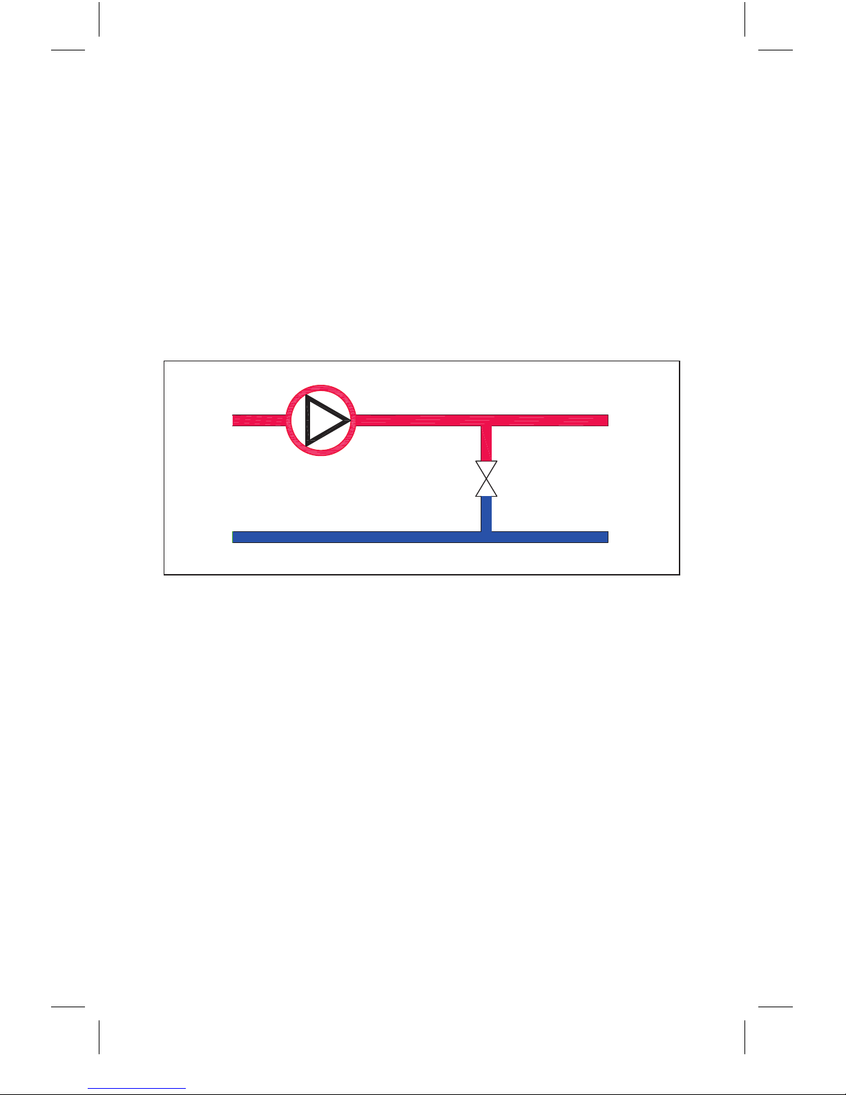
9. Use with a bypass valve
Installation and application: The pump should be installed according
to the diagram below.
If all the thermostatic radiator valves in the system are closed, a bypass
valve allows water to continually circulate eliminating unnecessary heat
and pressure build up.
If the system has a manual bypass valve (non TRV radiator) select speed
I and adjust the flow rate of the system to the minimum specified by the
boiler manufacturer’s specifications. Once the flow is adjusted set the
pump to AUTO.
For systems with a thermostatically controlled bypass valve select speed
I and adjust the flow rate of the system to the minimum specified by the
boiler manufacturer’s specificatons. Once the flow is adjusted set the
pump to BL1 or BL2 to suit the system demands.
bypass valve
Page 12

12
10. Commissioning
The liquid in the heating system must be clean. It is recommended that
a proprietary magnetic filter be fitted to ensure that the system remains
clear of potentially damaging contaminants and debris.
Before operating the pump:
• Open both service valves and prime the system with water
• Bleed the system (not the pump) to ensure no air is trapped
• Pressurise the system to its lowest recommended level
Bleeding the pump: The CPA series pump has an automatic bleed
function and does not require manual intervention. In order to bleed
the pump carry out the following steps:
• Connect the pump to the electrical supply and switch on
• The pump will now automatically vent any air within it. Whilst doing
this the pump may appear as though it is not operating properly.
However normal operation will begin once the air has been vented.
This may take a few minutes
• To speed the venting process up the pump may be set to speed III
• Once the air has been removed the pump display will begin to show
that power is being used and the pump should be set up as in section 7
NOTE: Do not run the pump without water in the system as this will lead
to premature failure and invalidation of the warranty.
NOTE: Do not rely on the pump to vent air from the system once
commissioned. It is recommended that an automatic air vent is installed
to maintain an air free system.
Page 13

13
11. Settings and pump performance
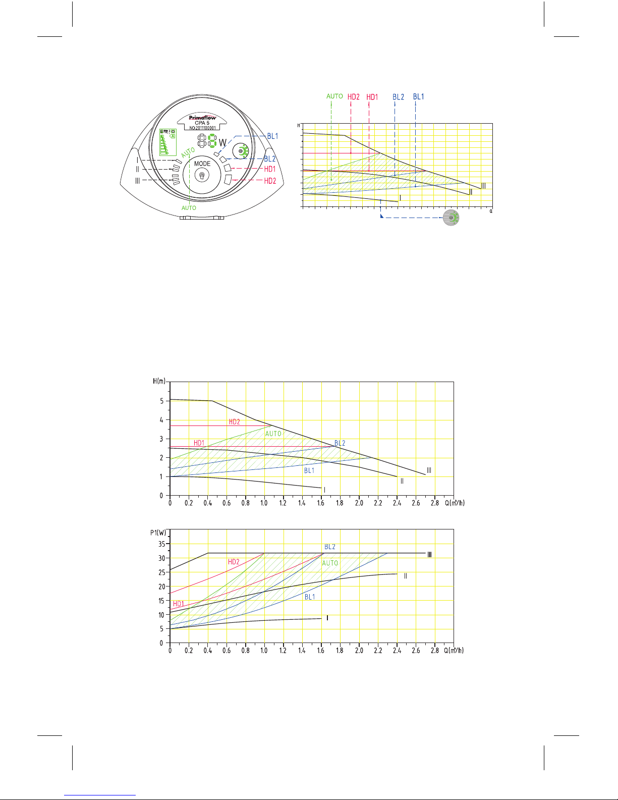
The table below describes each of the pump settings and its function.
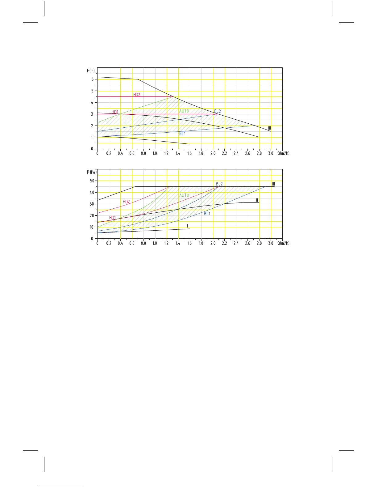
For each setting the pump has its own performance (Q/H) curve, but in
Auto mode the pump can adjust to anywhere in its operating range within
these curves. Input power curve P1 covers every Q/H curve, this is the power
consumption in any given condition within the curves. Power consumption
is measured in Watts (W) and displayed on the pump control panel.
Setting Performance curve Function
Auto Maximum rate to
minimum rate
The auto function will adjust the pump
performance to anywhere within the
standard range to obtain the optimum
setting for the demand of the system.
BL1 Lowest proportional
pressure curve
Dependant on the demand of the
system the pump will adjust itself up
and down this curve. As demand
increases so does the pressure.
BL2 Highest proportional
pressure curve
Dependant on the demand of the
system the pump will adjust itself up
and down this curve. As demand
increases so does the pressure.
HD1 Minimum constant
pressure curve
Dependant on the demand of the
system the pump will adjust itself
up and down this curve. The pump
will maintain a constant pressure
regardless of the system demands.
HD2 Maximum constant
pressure curve
Dependant on the demand of the
system the pump will adjust itself
up and down this curve. The pump
will maintain a constant pressure
regardless of the system demands.
III Speed III The pump will operate on the
maximum curve in all conditions.
II Speed II The pump will operate on the
medium curve in all conditions.
I Speed I The pump will operate on the
minimum curve in all conditions.
Night
mode
Night mode The pump will operate at a minimum
performance and power levels if certain
conditions are met.
Page 14
14
The pump curves relate to the following characteristics:
• Water with air fully vented from system
• Adaptive density (ρ) is 983.2 kg/m3 with a liquid temperature of +60°C
• All curves show average values and variation between pumps may
exist. Tests should be conducted on individual pumps if a specific
curve is required
• Adaptive kinematic viscosity is 0.474 mm2/s (0.474 cST)
Performance curve for CPA5 pump (5 bar)
Pressure
Volume flow
Volume flow
Power
Page 15
15
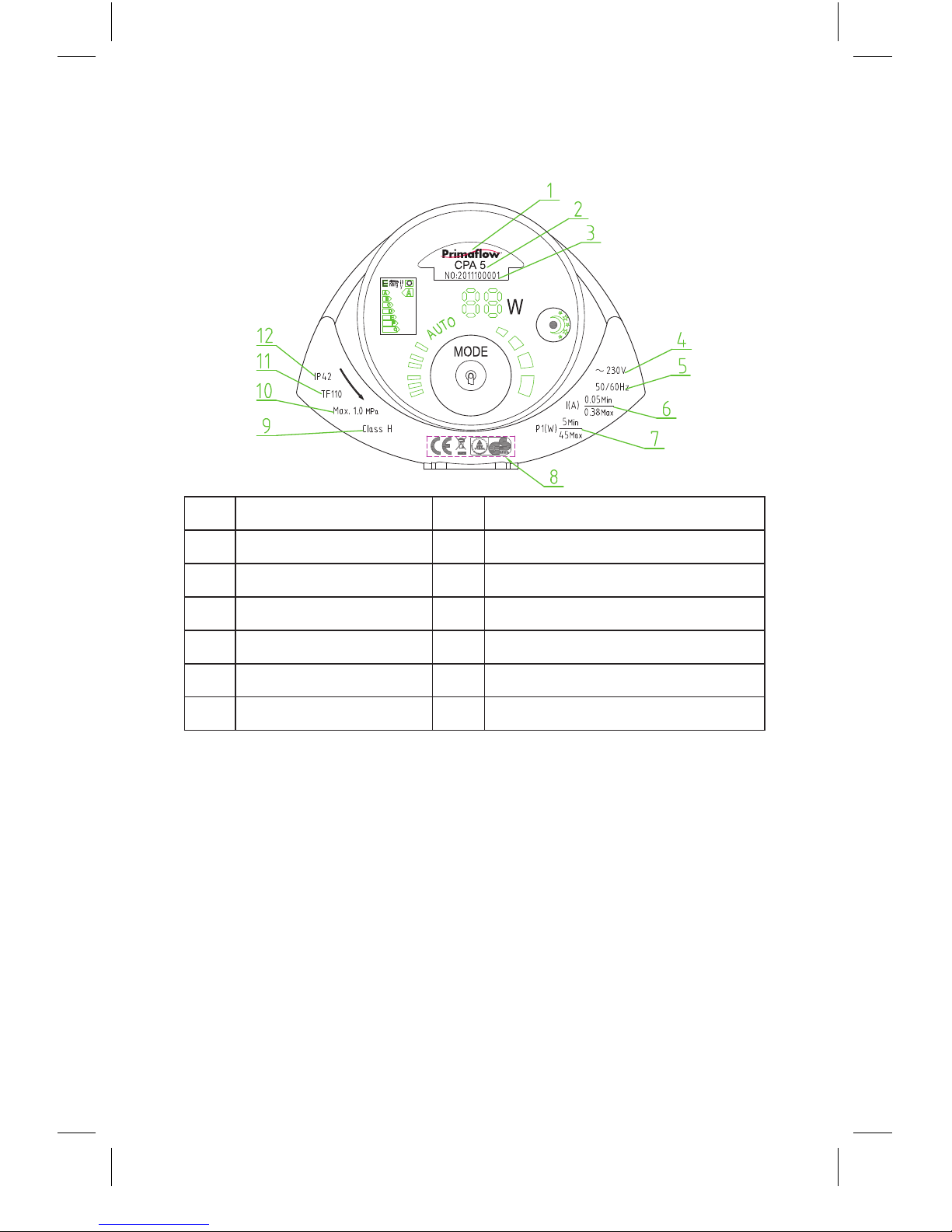
Performance curve for the CPA6 pump (6 bar)
PressurePower
Volume flow
Volume flow
Page 16
16
12. Features
Name plate information
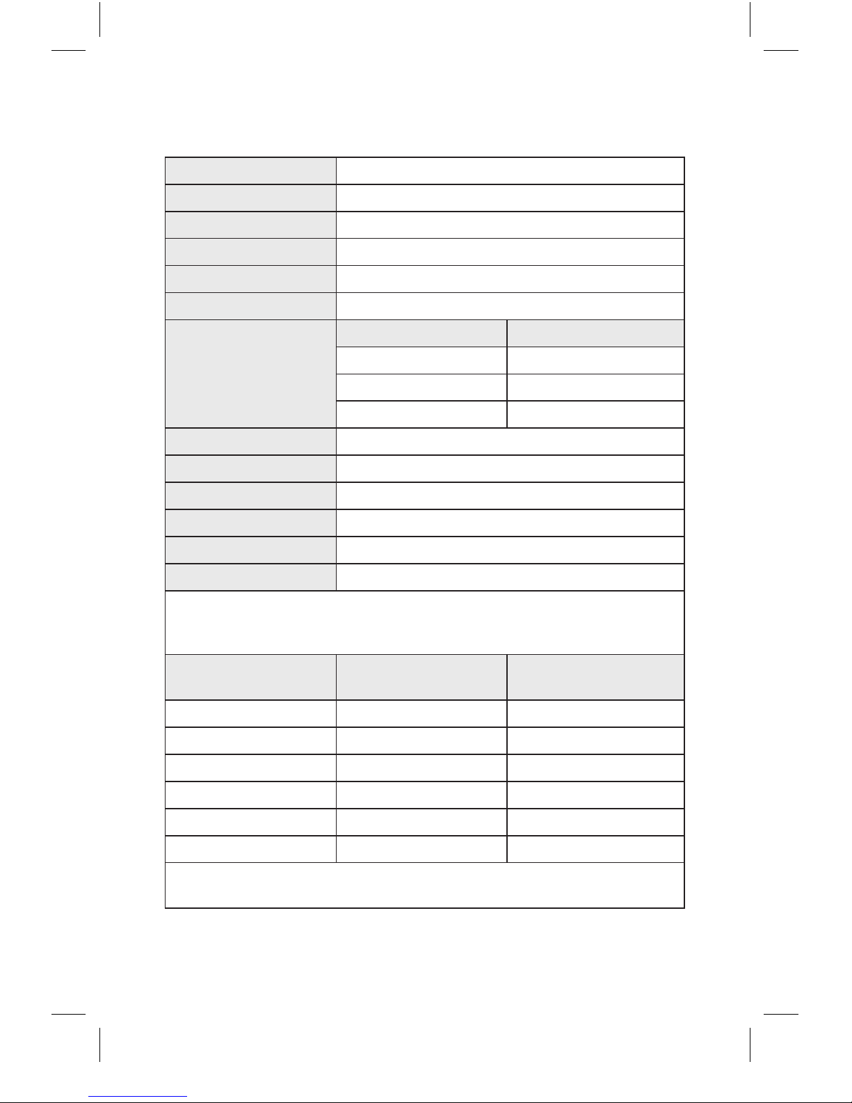
Pump designation:
Pumps are designated as follows: CPA5 / CPA6
CP: Circulating pump
A: A-Rated / EuP compliant
5/ 6: Head of pump in meters
No. Description No. Description
1 Primaflow 7 Watts (min & max)
2 Pump type 8 Certifications
3 Serial number 9 Insulation class
4 Voltage 10 Maximum system pressure
5 Frequency 11 Maximum temperature
6 Amps (min & max) 12 Protection grade
Page 17
17
13. Technical specifications
Voltage 230V +6% / -10%, 50Hz, PE
Protection No external protection
Protection grade IP42
Insulation class H
Air humidity Ma x 95%
System pressure 1.0 M pa
Inlet pressure
Liquid temp Min pressure at Inlet
<75°C 0.05 MPa
<90°C 0.025 MPa
<110° C 0.10 8 M P a
EMC standard EN61000-6-1 and EN61000-6-3
Acoustic level <42dB (A)
Ambient temperature 0°C to 40°C
Temperature grade TF110
Surface temperature <125°C
Liquid temperature 2°C to 110°C
In order to prevent condensation inside the control box and stator it is
recommended the water being pumped is always at higher temperature
than the ambient temperature.
Ambient
temperature (°C)
Minimum
pumped temp (°C)
Maximum
pumped temp (°C)
0 2 110
10 10 110
20 20 110
30 30 110
35 35 90
40 40 70
It is recommended that the water in domestic hot water systems is kept
below 65°C to reduce the risk of scalding.
Page 18
18
15 Troubleshooting
Ensure the electrical power is isolated before carrying out any repairs.
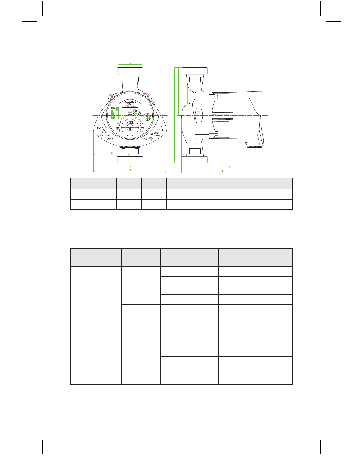
14. Dimensions (in millimetres)
Model L1 L2 B1 B2 H1 H2 G
CPA5 65 130 69 138 129 156 1.1/2 ”
CPA6 65 130 69 138 129 156 1.1/2 ”
Problem Control
panel
Possible reason Actions
The pump is
not running
Power
indicator is
not lit
Blown fuse Replace fuse
Circuit breaker
has been tripped
Reset circuit breaker
Faulty pump Replace pump
Display
shows “E”
Low voltage Check supply voltage
Impeller is blocked Clear impeller
Excessive noise
in the system
Normal Air in the system Bleed system
Excessive flow rate Lower inlet pressure
Noisy pump Normal Air in the pump Bleed air from pump
Low inlet pressure Increase inlet pressure
Insufficient heat
from the system
Normal Pump setting
is too low
Adjust pump setting
Page 19

19
16. Warranty
The Primaflow CPA pump is sold with a 2 year warranty effective from
the date of installation, subject to the return of the enclosed warranty card
within 15 days of the installation date. If the warranty card has not been
returned the warranty will expire 2 years after the date of manufacture.
This warranty covers any manufacturing defect which causes premature
failure of the pump whilst within its warranty period. The warranty is valid
on the assumption that
• the product has been installed and used as specified in the
Installation, operation and maintenance guide
• the installation complies with all local building regulations
• the installation was carried out by a competent and qualified person
The warranty is invalid if the pump
• has not been installed by a competent person
• has been used other than for the purpose for which it was designed
• has not been used in accordance with the Installation, operation
and maintenance guide
• has not been installed correctly in accordance with the Installation,
operation and maintenance guide
• has not been removed from the heating system in a workmanlike fashion
• has been damaged by outside interference e.g. physical damage or
inappropriate dismantling
• has failed outside the warranty period specified
Primaflow does not accept any liability for damage caused by a third
party, nor will Primaflow be responsible for malfunction caused by
inappropriate operating conditions or force majeure.
Primaflow reserves the right to reject any warranty claims not covered
in this statement.
Page 20

 Loading...