


Supplied By www.heating spares.co Tel. 0161 620 6677
·
·~
~
POTTERTON
30F, 40F, 50F, 60F,
balanced
flue
THIS APPUANCE
gas
IS
FOR
USE WITH NATURAL
80F
& 1
fired
OOF
boilers
GAS
(G20)
ONLY
'
-
fanned
Installation
LEAVE THESE INSTRUCTIONS
and
Servicing
ADJACENT
Instructions
TO THE
GAS
METER.

Supplied By www.heating spares.co Tel. 0161 620 6677
CE
SAFETY, PERFORMANCE & QUALITY
Prima F boilers have been assessed
of
'Essential Requirements'
The Directive
construction, and use
and monitored system of quality assurance.
BSI kitemark remains
The
performance and
POTTERTON
POTTERTON
POTTERTON
lays
down
quality (BS.5750) standards.
PRIMA
PRIMA
PRIMA
30F G.C.
40F
SOF
the European
requirements for the safety and efficiency of the appliance, together with its design,
of materials. It also requires
on
the product. demonstrating continued conformity with
No.
41.607.01
G.C.
No.
41.607.02
G.C.
No.
41.607.03
CONTENTS
General
Optional Extras
Accessories
Installation Data
Boiler Dimensions
Site Requirements
Technical Data
Installation Instructions
Commissioning
Health and Safety Information
Control
Wiring Guide
User's Instructions
Systems, Pipework and
Literature
by
a Government appointed Notified Body and
Gas
Appliance Directive.
the
production process to
POTTERTON
POTTERTON
POTTERTON
PRIMA
PRIMA
PRIMA
IMPORTANT
Page No. 2
Page No. 2
Page No. 3
Page No. 3
Page No. 3
Page No. 3
Page No. 6
Page No. 11
Page No.
Back Page
Supplied
18
in
Pack
The appliance
competent
(Installation and Use) Regulations 1984.
Prima F boilers (formerly
are certified
that no
economisers,
appliances
instructions
Any
approved
certificate and
external control devices (e.g. flue dampers,
direct
must
person
by
BSI
etc.)
unless
or
otherwise
connection
by
Potterton
the
normal warranty.
shown
be
covered
the
relevant BSI safety,
60F
G.C.
80F
G.C.
100F
G.C.
be
installed
as
stated
known
for
safety. it is therefore important
be
directly
covered
recommended
of a control
could
to
meet the
by
an approved
No.
41.607.04
No.
41.607.32
No.
41.607.33
and
serviced
in
the
Gas
as 'Profile Prima')
connected
by
these
invalidate
installation
in
device
to
the
by
a
Safety
these
writing.
not
BSI
GENERAL
Prima F boilers are fully automatically controlled, wall
mounted.
using a cast iron heat exchanger and are available in
outputs
six
100,000 Btulh).
The boilers which are designed
hot
INDIRECT FULL y PUMPED systems only, which may
be sealed
The boilers can
types of
Standard
for a
fan
powered,
ranging
water
and/or
or
flue system:
horizontal
wall thickness of 100mm {4in) to 510 (20in).
central
open vented.
be
supplied with either of the following
balanced
from
heating
flue
flue
5.86-29.3
to
provide domestic
must
system
appliances,
kW
be
which
(20,000-
is
used
suitable
on
PRIMA 100F MODEL ONLY
1
metre
maximum flue length of 955mm (37in).
Vertical
through a
980mm (38in) measured from the top
of
PRIMA 30F, 40F, 50F, 60F & 80F Models only
2
metre
maximum
Vertical
through a flat roof and terminate
1980mm (78in) measured from the top of boiler case.
of
OPTIONAL EXTRAS
The following are kits available as optional
lnternal Fitment Kit, which is suitable for a maximum
wall thickness of 510mm (20 in.) is
to
access
Pump
designed
valves installed above the boiler.
be fitted above
used).
Terminal
to the outside
after making good around the
the outside wall is impracticable.
Cover
Kits
located
to
conceal the pump, and/or any motorised
the
wan
Plate, where necessary can
wall face to improve the appearance.
boiler
on
if
to
top
(Note:
the
vertical
terminal.
extras:-
be used where
of
the
boiler
Pump cannot
flue
be
and
kit
fitted
is
Terminal
fitted less
above a flat roof
45°
flexibility (Prima
Vertex
flexibility
only).
Full
SEE PAGE
OPTIONS.
2
horizontal
Flue
system
flat roof and terminate at a maximum height
horizontal
flue length
flue
system
Guard,
than
and
90°
Flue
through
fitting instructions are provided with each kit.
10
flue
system
which allows
flue
system
of
1955mm (77in).
which allows
to
be
used
2m
above a balcony, above ground
to
which people have access.
Flue
Bend
Kits,
30F
to 60F only).
Kit,
giving
a roof
FOR PART Nos. OF FLUE KITS AND
space
which
which
at
a maximum height
when
giving greater flueing
greater
(Prima
provides
the
flue
of
boiler case.
provides
the
flue
the
vertical
to
to
terminal
30F
pass
pass
flueing
to
a
a
is
or
60F

Supplied By www.heating spares.co Tel. 0161 620 6677
ACCESSORIES
The following Potterton Myson controls are
recommended
Electronic Programmer EP2001,
Cylinder Thermostat PTT2
Room Thermostat PRT2
for
use with your boiler:-
or
PTI100
or
PRT100
EP300i.
or
EP6000
Frost Thermostat PRT100 FR
INSTALLATION
The installation
with
the
latest
Safety
{Installation and
building regulations, IEE Wiring Regulations and the
Byelaws
of
Detailed recommendations are
following British Standards and Codes of Practice.
BS6798, BS5440 Part1
of
the boiler must be
relevant
requirements
Use)
the
Local Water Undertaking.
in
accordance
of
the
Gas
Regulations, local
contained
in the
BOILER
RETURN
Motorised
Zone Valve MSV222
Motorised Diverter Valve MSV322
Thermostatic Radiator Valve
Data Sheets describing these products are available
on
request.
DATA
BS5440 Part 2 BS5449 Part1
BS5546 BS4814. BS6891.
BUILDING REGULATIONS.
MODEL
BRITISH
GAS
WATER BYELAWS.
GAS
SAFETY
REGULATIONS.
BUILDING STANDARDS (SCOTLAND)
REGULATIONS.
DIMENSIONS
or
MSV228
PUBLICATION DM2.
(INSTALLATION
·so
(60)
AND
USE)
srr
srr
FIG. 1
Boiler
Dimension 'A'
(mm)
Flow/Retum
Connections
'B'
'C'
'D'
30F
350
110
103
87 87
22mm
Copper
These boilers are not suitable for external installation
and should not
appliance. The boiler may
although particular attention is drawn
ments of
the
current
Scotland, the electrical provisions of the Building
Standards applicable in Scotland with respect to
40F
350 350
110
103
22mm
Copper
Copper
50F
110
103
87
22mm
60F
3SO
110
103
107
22mm
Copper
80F
425
150
143
107
28mm
Copper
SITE
be
fitted directly above a cooking
be
installed in any room,
to
the require-
l.E.E.
Wiring Regulations and
100F
425
150
143
107
28mm
Copper
REQUIREMENTS
installation
or
Where a room-sealed appliance is installed in a room
in
the
containing a bath or shower, any electrical switch or
appliance control, utilising mains electricity should
situated that it cannot
bath or shower.
3
600
I
1HE
100
I
BOltER
is
inverted).
*30
(40)
(40)
•NOTE:
IF
PIPEWORK
NORMAL CLEARANCE OF
ANDWALLCANBEINCREASEOT035mmlFDESIREDBYIN\/ERTINGTHE
BOILER MOUNTING
(Dimensions in
IS
TO BE RUN DOWN
25mm
PLATE DURING INSTAUATlON
brackets
apply
of
the appliance in a room containing a bath
THE
BACK OF
BElWEEN THE REAR OF THE BOILER
when the mounting plate
shower.
be
touched
by
a person using the
be
THE
so

Supplied By www.heating spares.co Tel. 0161 620 6677
FLOW
PIPE
RETURN PIPE
CONTROL
THERMOSTAT
PUMP OVER-RUN
THERMOSTAT
THERMOSTAT
CAPILLARY
RETAINING CLIP
~
/
FLUE
ELBOW
FAN
SUPPLY
LEADS
CONNECTOR
FAN
FLUE
HOOD
HEAT
EXCHANGER
OVERHEAT
THERMOSTAT
POCKET
BOILER DRAIN
CAP
ELECTRODE~
PILOT
GAS
COCK
COMBUSTION
CHAMBER
AIR
DEFLECTOR
CHANNEL
MAIN
BURNER
PUMP
OVER-RUN
THERMOSTAT
CONTROL
BOX
GAS
VALVE
CONTROL
FIG. 2 GENERAL
BURNER
TEST
POINT
PRESSURE
ARRANGEMENT
4
\
OVERHEAT
THERMOSTAT
CODE
CONTROL
THERMOSTAT
BADGE

Supplied By www.heating spares.co Tel. 0161 620 6677
Where
location, special
6798 gives detailed guidance
Ensure that the
enough for
the installation of the boiler will
procedures
gas
this
appliance
supply
may
on
pipe
and
be
this aspect.
and
any
run off the same meter. Reference
BS6891
Boiler
The boiler
of
to
local authorities
Mounting
must
combustible
take the
weight
Surface
be
mounted
material and
of
the boiler.
and
on
a flat wall,
must
The
the Building Regulations
be
adhered to.
IMPORTANT
TIMBER
If
the appliance is
it should
Publication
Framed Housing'.
from the local
Clearances
NOTICE:
FRAMED
to
be
fitted in
DM2
'Guide for Gas Installations in
Gas
Around
HOUSES
be
fitted in a timber framed building,
accordance
If
in doubt,
Region
the
advice
of
British Gas.
Boiler
The following minimum clearances
after installation, for correct operation
the boiler:
61
Omm (2 ft) at the front
Smm (0.2 in) each side
of
the boiler
of
the boiler
be
in an unusual
necessary
and
meter are large
others that
should
be
which
may
made
may
sufficiently
requirements
must
with
British Gas
must
be
must
be
maintained
and
servicing
BS
be
to
be
robust
of
the
be
Timber
sought
of
50mm
boiler case),
cover
(2 in)
is
to
at
the
except
be
fitted,
top
(measured from
where
when
the
178mm
optional extra
allowed.
100mm
Additional
installation for lifting
required at the
(4 in) at the
clearances
top
bottom
the
of
of
to
these are required during
boiler
the boiler for
the boiler.
and
connections.
Ventilation
If
the boiler is
a cupboard, the
must
be provided
each
of
TABLE
a compartment are given in
to
be
installed in a confined
space
at
the
which
should have a free area
1. Further details
will
need
top
and
for
installation
BS
ventilating.
bottom
6798.
TABLE 1
PRIMA
30F
40F
50F
60F
80F 43 277
100F
AIR
VENT
2
in
16 103
21
26 170
32 206
54
If the openings draw air from outside
free
areas
may
be
halved. Refer
for further guidance.
the
top
(7 in) should
127mm
access
to
space
Openings
of
the
cupboard
as
shown
of
a boiler within
AREAS
2
cm
135
349
the
building the
to
BS
5440
of
pump
(5
in) is
the
such
Part 2
the
be
pipe
as
in
Balanced Flue Terminal
The fresh air inlet
left, right, rear
the
terminal
on
and
the outside
The minimum spacings from the
and ventilation openings are
mation appertaining
reference should
be
flue
or
top
made
and
Ducting
ducts
can
be
run
from either
of
the
boiler
to
a miniature
of
the building.
terminal
shown
to
horizontal flue lengths
to
FIG.
to
obstructions
in FIG. 3. For infor-
4.
INFORMATION RELATING
PROVIDED
CAL
NOTE
Where a flue terminal is fitted less than 1000mm from a
plastic
an
underside of gutter
Any
If a terminal is fitted less than 2m above a balcony,
ground
then a suitable terminal
or
above a flat roof
to
which
guard
people
should
be
have
fitted.
above
access
(P.l.L
a roof
and
suspect and further
No. 205792).
Ref
er
to BS5440 Part 1
Under
Carport.
FIG. 3
THE
for
further
--~-~~-~~-·---!"--.+-
SITING
FLUE
TERMINALS
guidance.
'fo
1--"-o..£.
L~
OF
BALANCED
/
!G
POSITION MINIMUM DISTANCE
A. DIRECTLY BELOW
B.
C. BELOW EAVES
0. BELOW A
E FROM VERTICAL DRAIN PIPES ANO
/
F.
G.
H.
I.
J.
K.
L HORIZONTALLY FROM A TERMINAL ON
M.
5
TO
VERTICAL FLUING IS
IN
THE PACK CONTAINING THE VERTI-
FLUE SYSTEM.
or
painted gutter
aluminium shield
car
port
or
other
or
a roof
and
two
other walls - the installation shall
WINDOW,
VENTILATION OPENING.
BELOW
SOIL
FROM
ABOVE ADJACENT GROUND OR BALCONY
LEVEL
FROM A SURFACE FACING THE TERMINAL
FACING TERMINALS
FROM
CARPORT INTO DWELLING
VERTICALLY FROM A TERMINAL
THE SAME
THE SAME WALL
ADJACENT
AIR VENT,
GUTIER.
BALCONY
PIPES
INiERNAL
OPENING
WALL
TO
OPENING
or
500mm from painted eaves,
of
1000mm length
or
eaves.
add-on
one
advice
AN
OR
DRAIN/SOIL
OR
OR
(DOOR/WINDOW)
extension should consist
other wall. If it consists
sought.
OPENABlE
ANY
OlHER
PIPE
CAR PORT ROOF
EXlERNAL
CORNERS
IN
ON
should
be
be
fitted
of
a roof
treated
1.200
1.200
1.500
to
of
as
300
25
25
25
75
25
300
600
300
150

Supplied By www.heating spares.co Tel. 0161 620 6677
REAR OR SIDE FLUEING
MAXIMUM
LENGTH'X'
=
FIG. 4 FLUE LENGTHS
ELECTRICITY
A 240
fused
with
and
voHs-
to
the
any
current rating
3 amperes and have a cross sectional area
0.75mm2
The
supply to the boiler and its associated equipment
SUPPLY
50Hz, single
3 amperes, must
latest edition
other
local regulations
of
the wiring to the boiler must exceed
in
accordance with BS 6500. Table 16.
of
the
phase
be
provided
1.E.E.
electricity
in
Wiring Regulations
that
may apply.
accordance
of
at
supply
The
least
STANDARD
SYSTEM
1
METRE
SYSTEM
100F
2METRE
SYSTEM
30f.
MODELS
should be controlled
pole switch {having
in
both
poles)
supply
can
be achieved
RULE
MODEL
FLUE
40F.
50F'
ONLY
so
that
FLUE
by
at
be carried out in safety.
GAS
SUPPLY
A
gas
supply pressure
inlet
to
the appliance. Performance
·use of reference
gas
ONLY
60F & 80F
an
least
complete
to
of
G20.
1955mm
exclusive
3mm
contact separation
isolatron
enable
20
mbar
s1omm
(2Qin)
955mm
(37in)
(nin)
3A
fused
from
servicing
work
is required at
data
is based
double
the
to
the
on
Maximum working head
Minimum working head
Gas supply pressure
Maximum flow temperature
Electricity supply
Internal Fuse
Power Consumption
Gas supply connection
Appliance lift weight (min)
Appliance weight
installed
Water content
Row/Return connections
TECHNICAL DATA
30.Sm (100ft)
150mm.(6in}
20mbar
82°C
240v-50Hz fused at 3A
TypeT1A
80
Watts (excluding pump)
Re. 1h (%in BSP female)
30F, 40F, 50F & 60F Models
26.0kg
37.1
2.0 litre (0.44 gal)
(57.31bs)
kg
(81.81bs)
22m copper
80F & 100F Models
33.Skg
46.4kg
(73.871bs)
(102.31bs)
2.4 litre (0.53 gal}
28mm
copper
6
Supplied By www.heating spares.co Tel. 0161 620 6677
I
I
BOILER
SIZE
INJECTOR
SIZE
GAS RATE
m%
(ft%)
INPUT
kW(Btu/h)
OUTPUT
kW(Btu/h)
BURNER
mbar
PRESSURE
iowg
i
l
30
l
40
150
100
60
80
Min
Max
Min
Max
Min
Max
Min
Max
Min
Max
Min
Max
2.9mm 0.87(30.61) 9.29(31686)
3.1mm
3.5mm
3.6mm 1.89(66.84) 20.28(69182)
4.4mm
4.7mm 3.10(109.38)
0.71
(25.23) 7.65(26116)
1.03(36.23) 10.99(37500)
1.06(37.40)
1.21
(42.86)
1.37(48.31)
1.39(49.11)
1.54(54.35)
1.71
(60.39) 18.32(62500)
1.73(61.07)
2.05(72.46) 21.98(75000)
2.13(75.19) 22.81(77821) 17.58(60000)
2.43(85.94)
2.74(96.62)
2.78(98.09) 29.75(101523) 23.45(80000)
3.42(120.77) 36.64(125000)
11.35(38710)
13.00(44360)
14.65(50000)
14.90(50826}
16.49(56250)
18.53(63211) 14.65(50000)
26.07(88945) 20.52(70000) 8.7
29.31(100000) 23.45(80000)
33.18(113208) 26.37(90000) 9.9 4.0
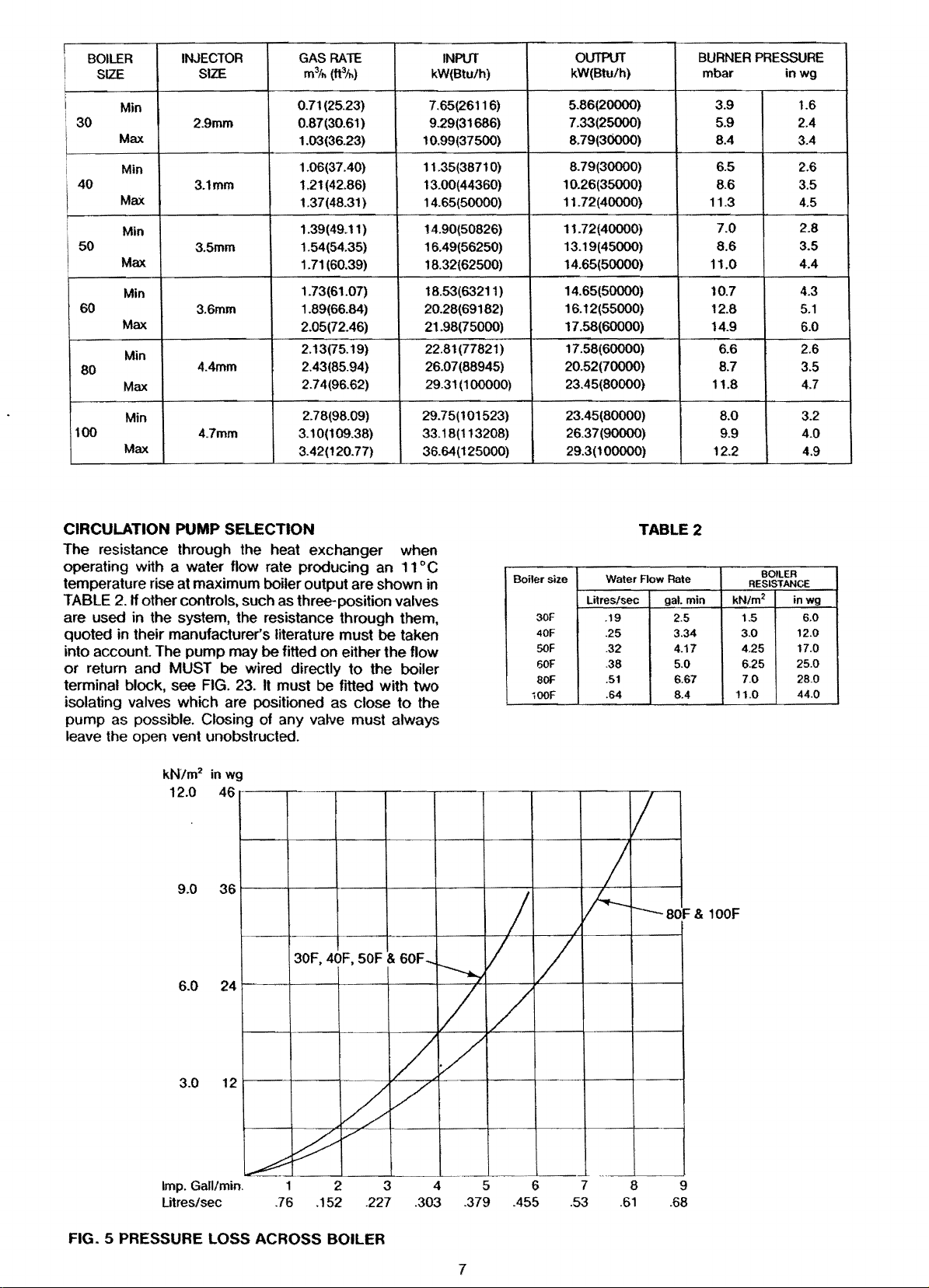
CIRCULATION PUMP SELECTION
The resistance through the heat exchanger when
operating with a water flow rate producing
temperature rise at maximum
TABLE
2.
If other controls, such as three-position valves
boiler output are shown in
an
11
° C
are used in the system, the resistance through them,
quoted in their manufacturer's literature must be taken
into account. The pump may be fitted on either the
or
return and MUST be wired directly
terminal block,
isolating
pump as
see
FIG.
23. It must be fitted with two
valves which are positioned as close
possible. Closing of any valve must always
to
flow
the boiler
to
the
leave the open vent unobstructed.
5.86(20000)
.33(25000)
7
8.
79(30000) 8.4
8.79(30000)
10.26(35000)
11.72(40000)
11.72(40000)
13.19(45000)
14.65(50000)
16.12(55000)
17.58(60000)
29.3(100000)
TABLE2
Boiler size Water Flow
Litres/sec
30F
40F
50F
60F
80F
iOOF
.19
.25
.32 4.17 4.25
.36 5.0 6.25
.51 6.67
.64
3.9
5.9 2.4
6.5
8.6
11.3
7.0
8.6
11.0
10.7
12.8
14.9
6.6 2.6
11.8 4.7
8.0
12.2 4.9
Rate
gal.min
2.5 1.5
3.34
6.4
BOILER
RESISTANCE
2
kN/m
3.0
7.0
11.0
1.6
3.4
2.6
3.5
4.5
2.8
3.5
4.4
4.3
5.1
6.0
3.5
3.2
inwg
6.0
12.0
17.0
25.0
28.0
44.0
kN/m2 in wg
12.0
Imp. Gall/min.
Litres/sec
46
·---r--··~·~--~·-~--~·~-~--~-~-r~
1 2 3 4 5 6
.76 .152 .227 .303 .379 .455
.53
BOF
& 100F
7
.61
8
9
.68
FIG. 5 PRESSURE LOSS ACROSS BOILER
7

Supplied By www.heating spares.co Tel. 0161 620 6677
The System
The
boiler
must
be
used
on
INDIRECT FULLY PUMPED
systems
The
static
minimum
On
tenninal block, it will
over-run thermostat.
continue
temperature b !1igh,
of
It is
valves are
when
with
heating
with a
within
If a three port divertervalve
a
open.
Where a
necessary. The total length
from
metres
lockshield
flow
FIGS
Systems fitted with
· operate
circuits are closed i.e.
static control valves,
capable of:-
1. Dissipating a
2.
A suggested
using a bathroom radiator fitted
valves
Additional system information
Control Systems, Pipework
Drain off
the
only,
which
system
head
should
does
of 150mm (6in).
all
systems
the
overheat thermostat.
important
the
controls
circuits
by-pass
the
by-pass
the
through
6.
7.
Maintaining a
boiler
is
boiler
the
to
run after
that
used
the
zone valves are closed. Also, systems
that
while
circuit
boiler.
is
not necessary since
pair
of
two
boiler
connections
of
22mm pipe. It
valve and
the
when
both
minimum
of
9 litres/min (2 gal/min).
method
shown
taps
and
in
should
in
may
be
designed
not
exceed
pump
then
This
boiler
thus
preventing nuisance operation
where
boiler
close
the
to
dissipate
port
be
adjusted
boiler
of
controls
the
mechanically
must
minimum
of
meeting
FIGS. 6, 7.
be
the
low
be
sealed
See
FIG 6.
should
be
will
ensure
electrically operated
is
wired
both
boiler
is
used
valves are used, a
of
the
should
should
4.5
litres/min
which
hot
water
be
fitted
of 1 kW
water
and
fitted
points
NOTE
Although
taps
empty
cap
the
system
installed
the
boiler
positioned
in
the
it
within
can
be
pipework
is
necessary
the
emptied
boiler
or
open
vented.
so
that
the
maximum
30.5m (100ft) and a
be
wired
to
the
controlled
shut
hot
is
still hot,
the
as
one
by-pass
to
with a by-pass
these
can
Wiring Guide.
in
the
of
around
to
case. See FIG. 2.
by
the
that
the
pump
down
if
the
so
it
does
not
water
and
must
residual heat
shown
be
maintain a
allow
and
(3400 Btu/h).
with
the
remove
in
FIGS. 6, 7
circuit
be
operated
flow
be
pipework
using
is
by-pass
circuit
greater
fitted with a
minimum
(1
gal/min)
the
central
through
requirements
two
lockshield
found
system.
the
the
system,
the
central.
be
always
than
boiler
heating
thermo-
close
drain
drain
boiler
pump
will
water
zone
cycle
fitted
fitted
from
taken
see
circuit
the
by
in
the
is
4
to
to
off
to
off
SEALED SYSTEMS
Installation
The installation
BS 6798 1987
"British Gas Specification
Heating
Systems"
must
and
comply
BS
5449
should
with the requirements
Part
1.
The B.G.
for
also
Domestic
be
consulted.
Wet
publication
Central
Safety Valve
A non-adjustable spring-loaded safety valve, preset
operate at 3
with
BS
It shall
or
vertically
valves are
valve. The valve
which
such
components
bar
(451bf/in
6759 Part 1 and
be
positioned
upwards
to
be
placed
should
permits
that
no
the
hazard
is
caused.
in
and
safe
to
2
shall
be
)
include
the
between
be
discharge
persons
a manual
flow
close
to
the
installed
used.
It
must
testing
pipe
either
honzontally
the
boiler.
No
boiler
and
into a discharge
of steam
or
damage
and
to
comply
device.
shut-off
the
safety
pipe
hot
water
electrical
Pressure Gauge
A pressure gauge incorporating a fi II
the
covering
system. It
the
same
at
should
be
range 0-4
should
point
visible from
bar
be
connected
as
the
the
(601bf
expansion vessel. Its location
filling point.
pressure
2
)
/in
shall
be
to
the
system, preferably
indicator,
fitted
to
Expansion Vessel
A diaphragm
shall
be
connecting
nominal). Pipework connecting
should
supporting
The nitrogen
vessel shall
of
the
vessel). To size
to
calculate
The
following
guide
to
Boiler Heat Exchanger: 6.5 litres
Small Bore Pipework: 1 litre
Micro
Bore Pipework:
Steel Panel Radiators:
Low Water Capacity Radiators:
Hot
water Cylinder:
type
expansion vessel
fitted
close
to
the
inlet side
pipework
not
incoporate valves of any sort.
the
or
not
top
point
the
volumes
calculating
should
vessel are supplied
air
charge
be
less
of
the
the
expansion vessel it
volume
the
not
pressure
than
the
hydrostatic
system above
of
water in
may
be
system volume.
be
less
the
by
the
used
system
7 litres
8 litres
system
2 litres
system
2 litres
to
BS4814 Part 1
of
the
pump.
than
15mm (%in
expansion
Methods
the
manufacturer.
of
the
expansion
head
the
expansion
is
first necessary
system
as
a conservative
per
kW
output
per
kW
output
per
kW
output
vessel
(height
in litres.
of
of
of
of
to
the
The
of
8

Supplied By www.heating spares.co Tel. 0161 620 6677
If the system is extended, the expansion vessel volume
may have to
been made for the extension. Where a vessel
calculated size is not
size should
boiler flow temperature is controlled at approx-
The
imately
The vessel size can now be determined from the follow-
ing table where V=System volume in litres.
Vessel Charge Pressure(bar)
Initial System Pressure (bar)
Expansion Vessel Volum.e (litres)
be increased unless previous provision has
available, the next available larger
be used.
82°C.
0.5
1.0
v x 0.11 v
of
the
1.0
1.0
x0.087
Cylinder
The hot water cylinder must be
cylinder fitted with an immersion calorifier suitable
direct
for operating at a gauge pressure
excess of safety
cylinders are not suitable for sealed systems.
valve setting. Single feed indirect
an
indirect coil type
of
0.3
bar
(51bf/in
or
2
)
a
in
Method
Provision shall be made for replacing water loss from the
system
i)
ii) where access to a make-up vessel would be difficult
Mains
There shall be
or
water even through a non-return
approval
of
Make-Up
either.from a make-up vessel
higher than the
ted through a non-return valve to
return side
all heat emitters.
or
by
using the mains
automatic pressurisation and make-up unit as
trated in FIG. 7 METHODS 1 and
top
of
hot water cylinder
or
tank mounted in a position
point
of
the system, and connec-
the
system
or
the return side
top
up
method
2.
or
a remote
on
Connection
no
connection to
to
the water storage tank which supplies domestic
of
the local Water Authority.
the
mains water supply
valve, without the
the
of
illus-
Filling Point
The system shall be fitted with a filling point at low level
which incorporates a stop
check valve (approved
be fitted in this order from the system mains, Refer to
FIG. 7. Method 1.
valve
to
BS 101 O and a double
by
the National Water Council) to
WATER
LEVEL
l--
TOP
OF
CASING
BOILER
I
BY-PASS
BALANCING
OPTIONAL
ZONE
OPTIONAL
3
PORT
·~---~--------<
I
VALVE
t
'
X-r
X-L
I
I
I
______
VALVES
~
~r
VALVE
~LJ
--.,
I
_j
ALTERNATIVE
ARRANGEMENT
BATHROOM
FITTED
VALVES
WITH
RADIATOR
XVENT
1 1
.-1...
1---1
..J
BY-PASS
USING
TWO
LOCKSHEILD
.---..
>--
t....
-
.J
THE
~
------------{.:>
FIG.
6 OPEN VENTED
Flrreo
WITH A COMBINED FEED AND VENT
FULLY
PUMPED SYSTEM
9

Supplied By www.heating spares.co Tel. 0161 620 6677
SAFETY
VALVE
A EXPANSION
u VESSEL
BOILER
PRESSURE
GAUGE
T---.
~
BY.PASS \
8AlANCINGVALVE
FILLING POINT
-----
OPTIONAL
ZONE VALVES
OPTIONAL~'
3PORTVALVE
~-~------~
' '
I I
X-L-
><VENT
~
~
~L
- J
,_,
L-J
<--J
·~\~~~---J.--~~
\
ALTERNATIVE BY-"ASS
ARRANGEMENT USING THE
BATHROOM RADIATOR
FITTED WITH
VALVES
CYLINDER
.__
·----c---------
TWO lOCKSHIELD
Y-KEUP
I VESSEL
I
I
I
I
--t>
Two methods
METHOD 1
MAINS TOPPING-UP
METHOD
NOTE:
This
system
to
the
method
may
only
Local
be
Water
Undertaking
HEATING
SYSTEM
'-='---+<lf-r-1KJ--------C><l-
of
filltng a
used
DOUBLE
CHECK
sealed
if
acceptable
VALVE
MAINS
WATER
SUPPLY
RV
ICE
!SE
VALVE HOSE
PIPE l
HOS(UNION
STOP TEMPORARY
FIG 7. FULLY PUMPED SEALED SYSTEM
FLUE KITS AND OPTIONS (See Page 2)
30F
Standard
1 metre
Flue
Flue
System
System
225540 225540 225540
NIA
2 metre Aue System 225543
Vertical
Flue
System 225157
40F
N/A
225543
225158 225159
of
filling a sealed
water system
j
SOF
NIA
225543
60F
225541
NIA
225544
225160
METHOD2
CISTERN FILLING METHOD
NOTE:
Cistern
to
be
temporary
pipe
or
cold
STOP VALVE
225541
225544
225161
connection
water
BOF
NIA
supplied
from
distributing
\
PRESSURE
REDUCING
llF
AEOVIREO)
100F
225542
225545
NIA
225162
a service
through
a
pipe
OVERFLOW]
CISTERN
;-
-t:><J--
PUMP
VALVE
STRAIGHT
FLUE
KITS
I
MAINS
WATER
SUPPLY
90"
Flue
Bend
45°
Flue
Flue
Elbow
(For
use with
Vertical
(For
use
1 metre
metre
2
Vertex
Flue
Vertex
Flue
Terminal
Terminal
Internal
Pump
Cover
Pump
Cover
Pump
Cover
Pump
Cover
Kit
Bend
Kit
Kit
Flue
Bends)
Flue
Terminal
with
Flue
Flue
System 225545
Flue
System 225544
Kit
Bends)
Kit
1 metre extension
Wall
Plate 212306
Guard 205792
Fitment
Kit
Kit
(Gin)
Kit
(7in
12in)
Kit
(13in
-18in) 225424
Kit
(19in -24in)
225600
225601
225602 225603
225606
225700
kit
84265
225183 225183
225422
225423
225425
225600
225600
225601 225601
225604
225607
225608
225545 225545
225544 225544
225701
84265
212306
225702
B4265
212306
205792 205792
225183
225422 225422
225423
225424
225423
225424
225425 225425
225600
225601
225605
225609
225545
225544
225703
84265
212280 212280
205792
225184
225422 225418
225423
225424
225425
10
NIA
NIA
NIA
NIA
NIA
NIA
NIA
NIA
205792
225184
225419
225420
225421
NIA
NIA
NIA
NIA
NIA
NIA
NIA
NIA
212280
205792
225184
225418
225419
225420
225421
FLUE
BEND
KITS
J_
VERTEX
FLUE KITS
OTHER
KITS
J_

Supplied By www.heating spares.co Tel. 0161 620 6677
INSTALLATION INSTRUCTIONS
It is the law that all gas appliances are installed and
serviced
Safety {Installation and Use) Regulations 1984.
For Health and Safety information see back page.
Electrical
competent
Wiring Regulations.
The boiler and its associated equipment will arrive
site in two cardboard cartons. The contents of each
carton is as follows.
CARTON 1
Boiler
Template
Literature Pack Containing:-
lnstallation and Servicing Instructions
User's Instructions
Control Systems Pipework and Wiring Guide
Auxiliary Pack Containing:-
Boiler Mounting Bracket
Gas
by
competent
testwork
person
:-
Boiler
Service Cock and Accessory Packs
SIDE
OF
REFERENCE
BOILER
persons
should
in
accordance
Pack
MARK
as stated in
be
carried
with
TOP
BOILER
out
the
OF
Gas
by
LE.E.
on
a
CARTON
Horizontal Flue Packs
Air/Flue Duct Assembly (length as ordered)
Flue Elbow Extension
Flue Terminal
Flue Sealing Collar
Rope Sealing Ring
Side Infill Panels-2 off
Vertical
Air/Flue Duct Assembly
Flue Terminal
Terminal
Vertical Flue
Accessory
Side Infill Panels-2
Flue
2:-
Flue
System
Flue Pack (2 cartons)
Cowl
Adaptor
Pack
Installation Instructions
Pack
off
HOLE WALL
FOR
'-....
A
D
0 '
FOLD
LINE
FOR
LH
FLUE
OUTLET
FIG.
8 TEMPLATE
Place template in proposed boiler position ensuring n
level (the minimum side clearances are automatically
allowed
REAR
Mark holes
boiler reference lines throught slots
SIDE FLUING
Mark hole positions 'A', 'D' and side
lines through
Mark large flue outlet hole and holes 'B' using the
thick lines on the template for minimum
the rear of
maximum
NOTE - Prima 30F, 40F
If
size
centrally
marking around the outside of the collar.
for)
FLUING
'A',
slots 'C'.
the
clearance. See note on Fig. 1.
a flue bend kit
is
obtained
over the marked flue outlet position, and
BOTTOM
'B', 'D', large flue outlet hole and side of
boiler and the
is
to be used. the correct flue hole
by
placing the
and
OF
50F
BOILER
thin
TEMPLATE
·c·.
of
boiler reference
clearance at
dotted lines for
only
wall
sealing collar
1s
SIDE
REF.MARK
SCREWS
FIG.
Remove template and carefully cut flue outlet
through wall. It necessary make good around hole to
enable holes 'B' to be drilled. (If internal flue fitment kit is
being used refer to instructions supplied with kit).
Drill holes 'A' using a 7 mm drill
Drill holes
Using wall plugs,
A)
level and the correct way up,
at
using the
Insert wall plugs into holes 'B' (accessory pack
hole 'D' (accessory pack
Insert flue sealing collar into wall and secure with screws
provided, (accessory pack
wall surface around flue sealing collar.
11
PLUG
FLUE
OUTLET
0
()
OF
BOILER
9 BOILER MOUNTING PLATE
attach boiler mounting plate to wall. Ensure that it
the rear of the boiler allowed for when marking out
-----
r;:::;.===~rT.e~---TOP
- - - -
C)
CUPWASHER
'B' and 'D' using a 5 mm drill
screws and washers {accessory pack
template. See also NOTE on
--
-a
.
L
-
0
i.e.
D).
B).
-~FIXING
REAR
"
to provide the clearance
Make good the internal
SEALING
COLLAR
FOR MIN.
CLEARANCE
FIG.
1.
SCREWS
hole
B)
and
is

Supplied By www.heating spares.co Tel. 0161 620 6677
FIG. 1
Oa
SIDE
i---
FLUE
·x·
-··~..;
I
CUTTING AIR/FLUE DUCTS
AG.
10b
REAR
FLUE
1. Measure from outside face
casing reference
2.
Take
air /flue duct assembly and measuring from the
flanged end, mark and cut the outer
flue duct to dimension 'x' plus 20mm. Ensure that
both ducts are cut squarely.
30F
to50F
FIG.
11
AIR/FLUE
line (dimension 'x').
TERMINAL
DUCT
of
wall to the side
INNER
DUCT
ASSEMBLY
duct
FLUE
of
and inner
boiler
1. Measure wall thickness (dimension 'Y').
2.
Take
air/flue duct assembly and measuring from
flanged end, mark and cut the outer air
flue duct to dimension
both ducts are cut squarely.
'Y', plus
duct
and inner
45
mm. Ensure that
NOTE
Cutting length remains the same for minimum or
maximum clearance at
AIR
DUCT
the rear of the boiler.
ROPE
SEALING
RINI'";
the
1.
Slide rope sealing ring on to air duct.
2.
Engage the terminal on
to
the ends
flue duct and press fully home.
FIG.
12
SECTIONAL
DUCT
ASSY THROUGH WALL
VIEW
OF
AIR/FLUE
of
the inner
3.
Engage four screws from accessory pack
the
pre-drilled holes in the terminal and screw fully
·c·
into
home.
These screws which are self drilling will pierce the
air duct and secure the terminal to air duct.
On models 30F
pilot holes in the air
4. Protect duct where it is likely to come into contact
with
mortar
(accessory pack E).
5.
Insert the assembly into
sealing ring along the air duct into the tlue sealing
collar.
Bend
inwards to retain the rope sealing ring. Ensure air
duct flange studs
onto mounting bracket.
to
50F, it is necessary to drill four
duct
by
using
the
adhesive
the
wall
six
tabs
on
flue
do
not obstruct lifting
tape
sliding the rope
sealing
provided
collar
of
boiler
12

Supplied By www.heating spares.co Tel. 0161 620 6677
FAN
FLUE OUTLET
SEALING
CONNECTOR
PLATE
DOOR
FIG.
13
PREPARING
COMBUSTION
CHAMBER FRONT
PANEL
THE
BOILER
BOILER
ASSEMBLY
MAIN
SECURING SCREW
ACCESS DOOR
The controls cover should have been removed
unpacking
opening the
underside
the
boiler,
door
of
controls cover, see
if
not remove controls cover
covering
the
securing screw
FIG
13.
when
on
the
by
Undo securing screw, pull controls cover forward 10 mm,
lower to release from four side fixings and
clear
of
thermostat knob.
Remove the
door
lift
Disconnect
Remove
remove
door
off
the
the
thumb
elbow
by
undoing
two
upper
two
flexible tubes from
the
lower fixing screws and
hinge brackets.
screw securing the flue
by
sliding forward
to
disengage
pull forward
the
flue elbow.
elbow
it
and
from its
rear retaining flange.
NOTE
The boiler
sealing plate removed.
required, remove
and transfer
is
supplied with the left hand flue outlet
If
another flue outlet direction
the
appropriate flue outlet sealing plate
it
to
the left hand position.
is
The boiler may now
if desired
the
by removing the fan/fluehood assembly also
be
lifted onto
its
appliance lift weight can
mounting bracket
be
further reduced
the
gas control assembly as follows.
1. Removing fan/fluehood assembly.
Disconnect
connector
the
fan
adjacent
supply
to
the
and earth leads from the
fan. Remove
the
two
nutssecuringthefluehoodtotheheatexchanger.Uft
out
fanlfluehood assembly.
2.
Removing burner/gas control assembly.
Remove
chamber
electrical
the
screws securing
the
combustion
front panel and remove panel. Unplug the
supply
leads
for
the
gas control valve from
the control box.
Remove
its
the
support
screw securing
bracket
the
gas
control valve
Disconnect electrode lead from electrode.
Remove
the
gas
two
screws securing
bottom
of
the boiler case and lift
control assembly.
the
burner assembly
out
the
or
burner/
wing
to
to
burner/
13
Supplied By www.heating spares.co Tel. 0161 620 6677
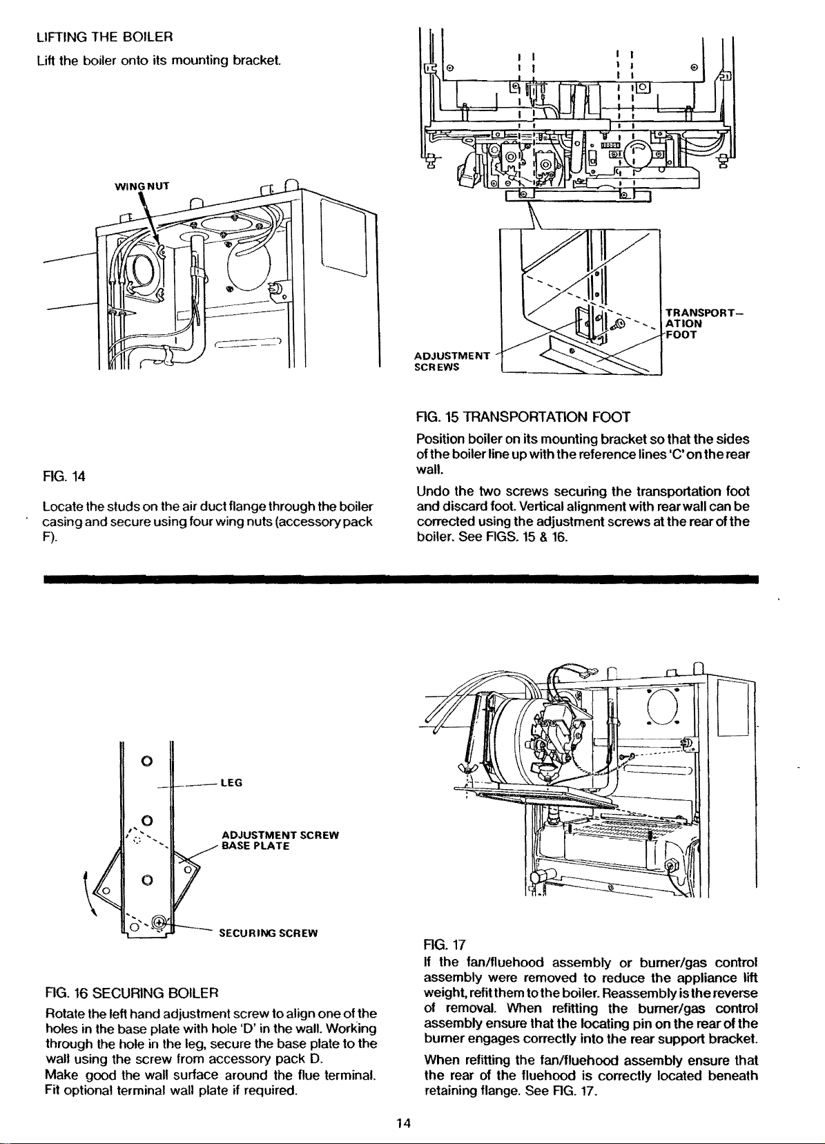
LIFTING THE BOILER
Lift the boiler
onto
its mounting
bracket
ADJUSTMENT
SCREWS
FIG.
14
Locate the studs on the air duct flange through the boiler
casing and secure using four wing nuts (accessory pack
F).
0
-LEG
AG.15
Position boiler on
of
wall.
Undo
and discard foot. Vertical alignment with rear
corrected using the adjustment screws at
boiler. See FIGS.
TRANSPORTATION FOOT
its
mounting bracket
the boiler line
the two screws securing
up
with
15 & 16.
the
so
reference lines
the
transportation foot
that
·c·
the
the
sides
on
the
wall can
rear
of
D
rear
be
the
ADJUSTMENT
BASE
PLATE
SECURING SCREW
SCREW
FIG.
If
the
assembly were removed
AG. 16 SECURING BOILER
Rotate the left hand adjustment screw to align one
holes in the base plate with hole 'D' in the
through the hole in the
wall using the screw from accessory pack D.
Make good the wall surface around the flue terminal.
Fit optional terminal
leg, secure the base plate
wall plate
if
required.
wall. Working
of
to
the
the
weight. refit them
of removal. When refitting
assembly ensure that
burner engages correctly into
When refitting the fan/fluehood assembly ensure that
the
retaining
14
17
fan/fluehood assembly
to
the
boiler. Reassembly is
the
rear
of
the fluehood
flange. See
FIG.
or
burner/gas control
to
reduce
the
locating
the
is
correctly located beneath
17.
the
appliance lift
the
reverse
burner/gas control
pin
on
the
rear of
rear support
bracket
the
Supplied By www.heating spares.co Tel. 0161 620 6677
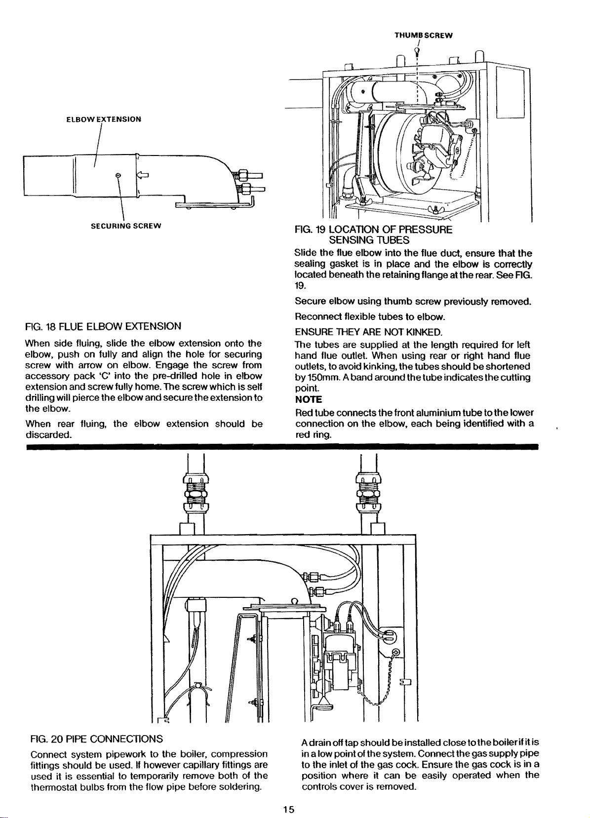
ELBOW EXTENSION
SECURING
AG.
18
FLUE
ELBOW
When side fluing, slide the elbow extension onto the
elbow, push on
screw with arrow on
accessory pack
extension and screw
drilling will
the elbow.
When rear
discarded.
fully and align the hole for securing
'C' into the pre-drilled hole
pierce the elbow and secure the extension
fluing, the elbow extension should be
SCREW
EXTENSION
elbow. Engage the screw from
in
elbow
fully home. The screw which is self
to
AG.
19
LOCATION
SENSING
Slide the flue elbow into the flue duct. ensure that the
sealing gasket is in place and the elbow is correctly
located beneath the retaining flange at the rear. See
OF
PRESSURE
TUBES
FIG.
19.
Secure elbow using thumb screw previously removed.
Reconnect flexible tubes to elbow.
ENSURE
The tubes are supplied at
hand flue outlet. When using rear
outlets,
by
point
NOTE
Red
connection on the elbow, each being identified with a
red ring.
THEY
ARE
NOT
KINKED.
the
length required for left
or
right hand flue
to avoid kinking, the tubes should be shortened
150mm. A band around the tube indicates the cutting
tube connects
the
front aluminium tube to
the
lower
FIG.
20
PIPE
CONNEGllONS
Connect system pipework to the boiler, compression
fittings
used it is essential to temporarily remove both of the
thennostat bulbs from the
should be used. lf however capillary fittings are
flow pipe before soldering.
A drain off tap should be
in a low point of the system. Connect the gas supply pipe
to the inlet of the gas cock. Ensure the gas cock is in a
position where it can
controls cover is removed.
15
installed close to the boiler
be
easily operated when the
if
it
is

Supplied By www.heating spares.co Tel. 0161 620 6677
ELECTRICAL
The boiler and all external control circuit wiring must
supplied from the same single isolating switch
and
socket
Care must be taken
is kept clear
and should
of
sharp edges and hot surfaces.
be
fused at 3A.
to
ensure that all wiring to the boiler
or
plug
be
EX1'ERNAL
ELECTRiCTJY
SUf>f'LV
EXTlRPiAl 3 Con
~~~~00
FIG.
21
PROGRAMMER
S
to3Cott
CONlAOL
VAlVES
ETC.
PRINCIPLE
JUCTION BOX
OF
WIRING
ROOMANS)/OR
CYllNt>ER
'THERMOSTAT
BOtU:R
SECU::HNG
SCREW
AG. 22 ACCESS
TERMINAL
TO
THE
BLOCK
BOILER
ELECTRICAL
The boiler tenninal
block
which
is
situated
in
the control
box is not designed to accept wiring from all the on site
controls and therefore
the
installer will usually need
to
incorporate a suitable junction box. This may not be
required
this incorporates a junction
shown in AG.
if a Potterton Electronic Programmer is used as
box. The principle of wiring is
21.
Further infonnation on wiring of system controls can be
found in the
Remove control
control
Control System, Pipework and Wiring Guide.
box
securing screw and lower the
box
to gain access to
the
boiler tenninal block.
Remove packaging from rear of the control box.
16
Supplied By www.heating spares.co Tel. 0161 620 6677
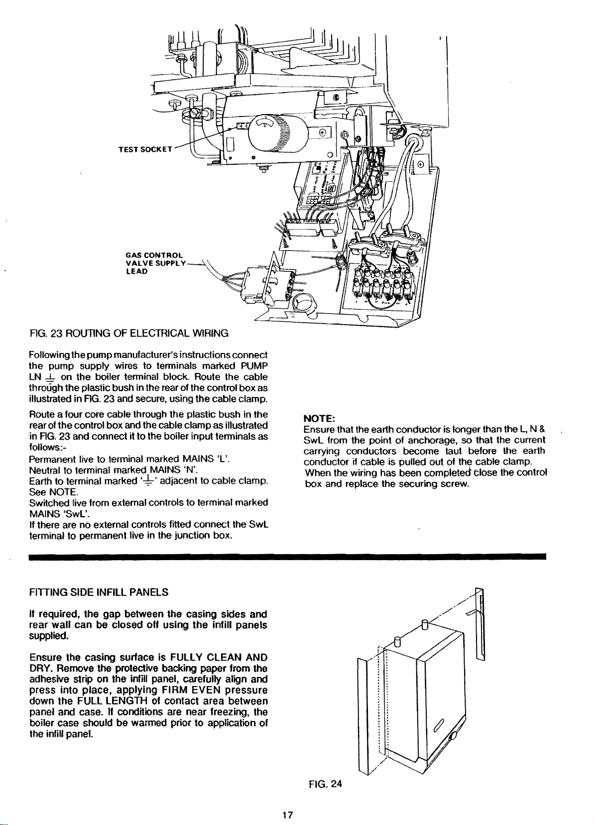
TEST
SOCKET
GAS CONTROL
VALVE
SUPPL V
LEAD
I I
AG. 23
Following the pump manufacturer's instructions connect
the pump supply wires to
LN
through the plastic bush in the rear of the control box as
illustrated in
Route a four core cable through the plastic bush in the
rear of the
in
follows:Permanent live to terminal marked MAINS 'L'.
Neutral to terminal marked MAINS 'N'.
Earth to terminal marked'-:!:-' adjacent to cable clamp.
See
Switched live from external controls to terminal marked
MAINS
If there are no external controls fitted connect the
terminal
ROUTING
...L.
on the boiler terminal block. Route the cable
control box and the cable clamp as illustrated
AG.
23 and connect it to the boiler input terminals as
OF
ELECTRICAL
terminals marked
AG.
23 and secure, using the cable clamp.
WIRING
NOTE.
'Swl'.
to
permanent live in the junction box.
PUMP
Swl
FITIING SIDE INFILL PANELS
required, the gap between the casing sides and
If
rear
wall can be closed
off
using the infill panels
supplied.
NOTE:
Ensure that the earth conductor is longer than the
Swl
from the point
carrying conductors become taut before the earth
conductor
When the wiring has been completedt:lose the control
box and replace the securing screw.
if
cable is pulled out of the cable clamp.
of
anchorage, so that the current
L,
N &
Ensure the casing surface is
DRY.
Remove the protective backing paper from the
adhesive strip on the
press into
down the
place, applying FIRM EVEN pressure
FULL LENGTH of contact area between
panel and case.
boiler case
should be warmed prior to application of
infill
If conditions
FULLY CLEAN AND
panel, carefully align and
are
near freezing, the
the infill panel.
FIG. 24
17

Supplied By www.heating spares.co Tel. 0161 620 6677
COMMISSIONING
Open
Vented
Remove the pump and flush out the system thoroughly
with
cold
Examine for leaks.
Sealed
NOTE:
The system can
pump
approved
SYSTEM' section Page 8 in these instructions, also
BS
Remove
cold water. Refit the pump.
the pressure gauge registers
Examine for leaks. Raise the pressure until the safety
valve lifts. This should
preset
correct
water gauge to this
All
The whole
should
purged
BS 6891.
Electrical
competent
Wiring Regulations.
Test
Tum boiler thermostat
with a break tank
6798
lift pressure
Systems
pilot unions for gas soundness
Unplug
control box and plug
the boiler thermostat knob, See AG. 23.
on
Tum
Ensure that the time control if fitted is in an
and that the room
fitted are set to high temperatures.
Switch
Gas will
ignition system
Using a leak detection fluid, check pilot unions for
gas soundness.
Tum
off
service cock.
Remove gas control
refit
the
control box. See AG. 23.
Systems
water. Refit the pump. Fill and vent the system.
Systems
be
filled using a sealed system filler
or
by
any other method
by
the
Local Water Authority. Refer
1987.
pump
and flush out the system thoroughly with
RH
and vent the system until
1.5
bar
occur
within ±
of
3 bar. Release water
cold
fill pressure, and set the indicator on the
value.
of
the
gas
installation including the meter
be
inspected and tested for soundness and
in
accordance with the recommendations
testwork
person
the
gas
gas at the gas service cock.
on
the external electricity supply
flow
to
the pilot only.
the external electricity supply and
plug into the socket on the left hand side of
should
in
accordance
to
control valve supply lead from the
it
into the test socket adjacent
and/or
is
de-energised.
valve plug from
be
carried
with
as
the
'O'
position.
cylinder thermostats where
tt
will not
be
th~
test socket and
to
'THE
(21.5 lbf /in2}.
0.3
bar
of
to
attain the
out
by
the
l.E.E.
follows:-
ON
condition,
to
the boiler.
ignited
as
the
to
the
gas
the
of
a
Refit the combustion chamber front panel.
Fit
the
case door into position
hinge brackets and secure it with the lower
screws.
Remove the temporary label
appliance, having ensured compliance
warnings
First
on
the
Ughtlng
label.
by
lifting it onto
from
the
two
front
with
the
top
fixing
of the
the
WARNING: Before lighting the boiler.ensure that the
CASE
DOOR
the sealing strip fitted
seal with the main boiler casing. Before proceeding
light the boiler, check that the external electricity supply
to the
boiler
is
in
the
on
Tum
Ensure that the
are open.
Ensure that the time control, if fitted
and that the room and/or cylinder thermostats, where
fitted are set to high temperatures.
Switch on the external electricity supply
After installation of the appliance, preliminary electrical
system checks must
carried
HAS BEEN CORRECTLY FITTED and that
to
the case
is
switched off and that the boiler thermostat
'O'
position.
the gas service cock.
out
pump
are:-
and radiator isolating valves
be
carried
door
is
forming a tight
is
in an on condition,
to
out
The checks
to
the boiler.
to
be
A Earth Continuity
B.
Short Circuit
C.
Polarity
D.
Resistance
Refer
to
Fault
Tum the boiler thermostat on and
after a period
be
observed through the sight glass in the front cover
the boiler. The time period can vary upwards of
seconds, depending
pipework.
Test for
using leak detection fluid.
Tum
NOTE:
There
switched
gas
the
boiler thermostat
could
on
to
Earth
Finding
of
time the main burner will light, this can
soundness around the boiler components
be
a delay in lighting if
and off and then on again rapidly.
Chart
on
the amount
to
·o·.
FIG.
30
to
a high setting and
of
the
control knob
45
air in the
of
is
SETTING
With the controls cover removed.
Fit a pressure gauge to the pressure test
supply pipe.
Turn
burner
accordance with values stated under TECHNICAL
DATA.
The burner pressure is set to the maximum output at
the factory.
AND
CHECKING
See
FIG.
2.
on the boiler thermostat and ensure that the main
is alight. Check that the burner pressure is
OF
CONTROLS
nipple in burner
in
If
follows, referring
SIT
Remove the plastic
valve
clockwise
decrease the pressure.
HONEYWELL
Turn
increase the pressure
pressure.
18
burner pressure adjustment is necessary
to
AG. 25.
GAS
CONTROL
and
turn the pressure adjustment screw antito
increase
the pressure adjustment screw anti-clockwise
VAL
VE
cap
from beneath the gas control
the
pressure
GAS CONTROL
or
clockwise
VALVE
proceed
or
clockwise
to
decrease the
as
to
to

Supplied By www.heating spares.co Tel. 0161 620 6677
HONEYWELL
PILOT
SCREW
(For test purpose only)
SPACER
I
SEALS
PRESSURE
FIG.
25
MAIN
BURNER
With the burner set
given
rate
obtained
reading
been
replace the plastic
Shut down the boiler remove the pressure gauge and
refit the screw in the test nipple ensuring that a tight seal
is made.
Remove the self-adhesive arrow from the inspection
ticket tied
Data Plate inside the
appropriate burner setting pressure.
Refit the controls cover.
Relight the boiler
Check for water leaks, turn the
system
Refill the system and
correct
to
the system design pressure.
in
TECHNICAL
and
this
at
least 1 O minutes after the main burner has
lit.
When
whilst hot.
cold
the
to
the burner supply pipe and stick it
fill pressure. Set the pressure gauge pointer
ADJUSTMENT
PRESSURE
to
its correct pressure, the firing
should
pressure
cap
and
on
be
on
the
controls cover
heat the system
sealed systems adjust
SCREW
ADJUSTMENT
DATA
SIT
should
checked
and
rate are
gas
control valve.
to
indicate the
to
boiler off, drain the
also
be
by
meter
correct
to
the
maximum.
to
the
PRESSURE
The thermostat has been calibrated
no
attempt should
the thermostat
main burner shuts down.
Pump
Over-Run
Will keep the
down, as
is
above 80°C.
The thennostat
Overheat
The overheat thermostat is pre-set and no adjustment is
possible.
condition occurs. Access to the reset button is through a
hole in the underside of the controls cover, see
long
Thermostat
It will require manually resetting if an overheat
be
made to re-calibrate it
to
the 'O' ·position and
Thermostat
pump
running after
as
the
water temperature within
is
preset and no adjustment
ADJUSTMENT
by
the makers and
on
check
the
boiler has shut
the
is
SCREW
site. Turn
that the
boiler
possible.
FIG. 2.
Other
All boiler mounted controls are designed
fault should occur they will fail safe.
checking is necessary.
Boiler
Controls
so
No
further setting
that
if
any
or
If a by-pass circuit is fitted the by-pass valve should
adjusted with the boiler operating under minimum load
conditions
boiler
operate under
Pilot
The pilot is pre-set and
pilot flame envelope should cover the electrode tip and
spark earthing strip see
illustrated, remove and clean the pilot as described in
the
Page22.
Boiler
At its minimum and maximum settings, the thermostat
should control the water
mately
to
maintain suff1eient water flow through the
to
ensure that the overheat thermostat does not
normal operating conditions.
Burner
no
adjustment
FIG.
29.
If
Servicing Instructions Section
is
required. The
the pilot flame
4,
PILOT BURNER,
Thermostat
flow temperature at approxi·
55°C-82°C
(130°F-180°F).
is
not as
be
External
Check that any other external control connected in the
system, such as
boiler as required.
User's
A User's Instructions leaflet is provided with this boiler
but the householder must have the operation
boiler
householder must also be advised of the importance
annual servicing and of the precautions necessary
prevent damage to the system and building, in the event
of the system remaining out of commission in frost
conditions.
19
Controls
clocks
Instructions
and
system explained
and thermostats, control the
of
the
by
the Installer. The
of
to

Supplied By www.heating spares.co Tel. 0161 620 6677
PERMANENT
LIVE
PUMP
r-----+o+------1
BLACK
l "
B 8
PUMP
.,..___
EJ
SWITCHED
AG.
l!VE
26
FUNCTIONAL
PR
FLOW
OWN
TESl
SOCKET
DIAGRAM
fl
OVERKEAt
THERMOSTAl
BOiLER
THERMOSYAT
WHllE
a-
WHrTE
BLUE
BROWN
EL£C1R0"1JIC
CONlROL
llTlA
1----~----:::..+--:_::
11
12
Sl
S:I
____
13
T•
TS
16
T1
T8
WHITE
BLUE (
1
SLACK
_...
OftANGE IHO•
WP.UTE
9ROWN
____
BLUE
---, y
r
L--(
~~-~-~--I~
iE
GV2
r ---
GVI
'
!NCI
"
~=TROl
VAlVE
AIR
PRESSURE
SWITCH
!Cl
FANN
HONEYWELL
AG.
27
BOILER
WIRING
DIAGRAM.
20

Supplied By www.heating spares.co Tel. 0161 620 6677
SERVICING
Regular skilled servicing and cleaning
of
the
appliance
INSTRUCTIONS
is essential to ensure continued safe and efficient opera-
tion. The frequency
particular installation conditions, and the use to which
the
appliance is put, but in general, once per year
should be adequate.
It is the law that all gas appliances are installed and
serviced
(Installation and
For Health and Safety
Electrical installation and servicing should be carried
out
by
competent persons as stated in Gas Safety
by
a competent person
of
cleaning will depend upon
Use) Regulations 1984.
Information see back page.
in
accordance with the
the
l.E.E. Wiring Regulations.
Servicing is best arranged
Potterton Myson Limited and further
from the
The boiler
attached to the inside
CODE NUMBER
ing spares or requesting information
control box.
All parts likely to require servicing are readily accessible.
By
removing the front door from the
components are exposed. Remove the front of the
combustion chamber to gain access to the main and
pilot burner and the ignition electrode.
Removal of the
the flueways in the heat exchanger for cleaning.
The following notes
but it should be remembered that attention must
local Potterton Regional Service Office.
DATA
PLATE
which should be quoted when order-
See
FIG.
removing the cover from the boiler controls and
flue elbow, fan and fluehood will expose
apply to the boiler and its controls
by
a contract placed with
details are available
and WIRING DIAGRAM are
of
the controls cover. The boiler
is on the front
2.
boiler, most
of
the
also oe
paid to the heating circuit itself including radiator valves,
thermostats. the time control and the expansion
teea water system.
immediately after the end
In all cases prior to servicing, light up the boiler and
check that the
flame and that the gas rate and main burner pressure are
correctly set.
servicing
mation given
WARNING
Before
external electricity
plug at the socket
switch.
NOTE: After completing any servicing or replacement
components check for gas soundness and carry
functional checks.
1.
PREPARING THE BOILER FOR SERVICING
See RG.13.
NOTE:
elbow fitted to the fluehood.
The
flued boilers.
A Remove controls cover
B.
If the pilot flame is satisfactory,
of
the pilot burner
the
start of any servicing work, switch off
Tum
off the gas service cock.
Boilers with side or rear flues have a flue
elbow is replaced by an adapter on vertically
covering the securing screw on the underside
the controls cover, see AG.
screw,
to
release it from its four side fixings and pull
forward clear of the thermostat knob.
Remove door
and
lift door off the two upper hinge brackets.
tt
is
advisable to clean the boiler
of
the heating season.
pilot and main burners have a clean, even
is
necessary and the infor-
in
'4. PILOT BURNER' can be ignored.
supply
or
pull controls cover forward 1
by
disconnecting the supply
switching off the external isolating
by
opening the door
13.
Undo securing
Omm,
by
undoing the lower fixing screws
no
<lnd
further
at
the
of
out
lower it
of
GAS
CONTROL
VALVE
PLUG
~-----,
"""'
'
............
,
..
'\
'
...............
,
'\
',
__
'\
'--...
FIG.
28
BURNER AND GAS CONTROL ASSEMBLY
21
·-.,.............__
GAS
CONTROL
VALVE/SUPPORT
BRACKET
SCREW
7BLADESON
30F, 40F,
8BLADESON
80F
BURNER
SECURING
SCREWS
50f
& 100F
& 60F

Supplied By www.heating spares.co Tel. 0161 620 6677
C.
Remove screws securing
front panel and remove panel.
D.
Disconnect
E. Remove
withdraw
On
vertically flued boilers remove
and
slide the vertical flue adapter
duct.
F.
Disconnect
connector adjacent
nuts
out
Lift
Lower and
G.
Undo the union on
H.
Unplug
valve from control box. See
I.
Remove
its support
J.
Disconned
K Remove
the
bottom
and gas control assembly.
the
two flexible
thumb
securing the flue
fan/flue
the
the
two
screw securing
elbow. Take care
the
fan
supply
to
hood
lift
out vertical adapter.
the
electrical supply leads
screw securing
bracket
the
screws securing
of
See
electrode lead from electrode.
the boiler case
the
combustion
tubes
from
the
notto
damage
two
up
and earth leads from
the
fan. Remove
hood
to
the
heat exchanger.
assembly.
gas
service
FIG.
FIG.
cock
for
28.
the
gas control valve
28.
the
burner assembly
and
lift out
chamber
the
flue elbow.
flue elbow and
the
gasket.
thumb
the
screws
into
the
the
two
outlet.
gas control
the
burner
flue
the
wing
to
to
B. Unscrew
the
assembly
the
operation.
C.
Lightly brush
Remove
replace.
pilot
pilot
the
to
and
injector
the
NOTE
Do
not
use a wire brush
D.
Gently clean
E.
Refit
the
assemble
F.
Secure
two
the
hexagonal screws.
G. Fully tighten
to
the
pilot.
following
commissioning
18.
H.
Ensure that
two
the
pilot
any
pilot
the
pilot
the
Check
the
the
hexagonal
main
shield
does
the
pilot
injector
deposits from
injector
pilot
to
assembly
union
for
procedure described
sedion
spark gap
head
burner
where
and
fitted,
not fall out during
to remove
and
clean its orifice
or
pin
to
the
to
the
the
pilot
tube.
to
the
nut
connecting
gas soundness
of
these
is
as illustrated in
screws securing
remove pilot
be
careful
any
clean injector.
electrode.
pilot burner
main burner using
the
at
instrudions.
that
this
deposits.
pilot
this
joint
in
FIG.
or
and
tube
by
the
Page
29.
2.
HEAT EXCHANGER
A
Working from above and below
use
a suitable tool and remove all deposits from
between the fins.
Slide vertical flue adapter into flue duct.
3.
FAN
A Separate fan from fluehood
securing screws.
carefully clean any deposits from around the fan
motor and its supports. Examine the fan
clean if necessary using a soft brush.
Re-assemble fan to fluehood ensuring that
sealing gasket is in place and in good condition.
Ensure also that the fan
retaining
Secure with
B.
Refit
rope seal
correctly located beneath
FIG.
C.
Slide flue elbow into
adapter and secure with
the
undamaged and in place.
D.
Reconnect the
ENSURE
bracket
two
the
fan/fluehood assembly. Ensure that
is
in
place and
17. Secure with
gasket between fan outlet and elbow
THEY
ARE
NOTE
Red tube
connection on elbow
identified with a red ring.
E.
Reconnect the fan supply and earth leads.
conneds
is
screws.
two
the
fl~xible
tul:>es
NOT
front aluminium tube
the
heat exchanger
by
removing
wheel and
located
the
wing nuts.
thumb
corredly
rear
of
the
fluehood
the
retaining flange. See
flue
dud
or
screws. Ensure
or
to
elbow
or
KINKED.
to
or
adapter each being
the
two
the
in
the
rear
the
is
lower flue
that
adapter
the lower
is
adapter.
RG.
PILOT FILTER
5. COMBUSTION CHAMBER INSULATION
A
6. MAIN BURNER
A.
4. PILOT BURNER
The following operations are only necessary if the pilot
is
flame
distorted
A Unscrew the pilot tube from
care not
or
the wrong size, ie
the
to
damage the electrode.
too
small.
pilot assembly. Take
22
29
PILOT
The
pilot
filter
situated
large
valve
therefore unlikely
event of pilot filter blockage
complete control valve should
Check
damage. If damaged replace as described
replacement.
Lightly brush any deposits from
and ensure there
venturi.
incorrect
cannot
control assembly
Clean
procedures not
disconnect
the
flanged connection and replace
injector.
BURNER
burner
within
and
designed
under
or
normal operating conditions,
the
combustion
If
on re-assembly
or
the
be
obtained, remove
replace
the
SPARK GAP TOLERANCES
is
proteded
the
to
to
need
is
no
correct gas rate
and
the
injector. In
rectifying
burner from
from blockage
gas
control valve. The filter
last
the
life of
the
replacing. However in
being
suspected
be
replaced.
chamber
fluff
in
the
the
bumerflame
thoroughly
the
the
the
insulation
the top
entry
or
burner
the
burner
clean
event
flame appearance,
gas
control valve at
the
by
gas control
of
each blade
of
the burner
picture
pressure
and
the
of
the
burner and
a pilot
is
it
is
the
the
for
under
is
gas
burner.
above

Supplied By www.heating spares.co Tel. 0161 620 6677
B.
Refit
the
burner and gas control valve assembly into
the
boiler, ensuring
burner engages correctly into
bracket
and undamaged between
case. Secure
C.
Refit
support
D.
Reconnect electrode lead
E.
Plug gas control valve
F.
Reconnect gas
on gas.
G.
Refit
CASESEAL
7.
Check
seal is
door.
RECOMMISSION
8.
Follow
in the COMMISSIONING section
instructions page
9.
OTHER BOILER MOUNTED UNITS
No further servicing
mounted units. Repair
10.
FAULT FINDING
Refer
Diagram
REMOVAUREPLACEMENT OF BOILER
MOUNTED UNITS
Make sure
the
screw securing
bracket
the
combustion
the
case
simply pressed into
the
full commissioning procedure as detailed
to
Fault Finding Chart AG.
RGS. 26, 27.
that
that
the
assembly with
supply
supply
chamber
door
seal. Replace
18.
is
the
locating
the
the
sealing gasket
the
burner flange
two
the
gas control valve
to
electrode.
leads into control box.
at gas service
front panel.
the
channel around
required on any
is
by
replacement
pin
on
the
rear
rear support
is
in
place
and
screws.
to
cock
and turn
if
damaged. The
of
other
30
and Wiring
of
the
the
the
these
boiler
MAIN BURNER
1. Switch off
disconnecting
the
external isolating switch.
the
external electricity
the
plug
at
2. Remove controls cover, case
chamber front
the
Boiler
3. Remove
described in
operations
4. Unscrew
pipe
to
the
to
damage
injector does
Remove
tube through the hole
5. Separate
flanged connection
screws.
NOTE: With
is
used
between
flange, requiring
See
FIG. 25.
6.
Unscrew
pressure test
panel as described
for
Servicing', operations
the
burner and
1.
'Preparing
G,
H,
I,
J & K
the
union nuts connecting
pilot and gas control valve. Take care not
the
electrode and
not
fall out during
sealing grommet and withdraw
in
the
the
burner from
by
removing
the
Honeywell
the
the
the
pilot, main burner injector and
nipple from
valve
use
gas
of
7. Use new sealing gaskets
8. Replacement
9. Follow
the
in
the
instructions. Page
is
the
reverse
full commissioning procedure as detailed
COMMISSIONING section
18.
supply
the
socket
gas
the
be
burner mounting flange.
the
gas control valve
control valve a spacer
outlet
two
the
on
of
or
switching off
door
and combustion
in
1.
'Preparing
A,
B and
control assembly as
Boiler
for
Servicing',
the
pilot supply
careful that the pilot
this
operation.
the
the
four
securing
and
the
burner
seals
at
this
burner.
reassembly.
removal.
of
by
C.
pilot
atthe
point.
these
GAS CONTROL
This operation
the burner and gas control valve
1.
Switch off the external electricity
necting
external isolating switch.
2. Remove controls cover, case
chamber front
the
Boiler for Servicing', operations A, B and
3.
Remove
described in
operations
4. Disconnect the electrical supply from the
Honeywell, note the individual wire positions.
With
Refer to
5. Unscrew the union connecting
to
the
6. Separate the gas control valve from
the
inlet and outlet ports
screws.
NOTE: With the Honeywell gas control valve a spacer
is
used
between
flange, requiring
See FIG. 25.
7.
Use new seals on reassembly.
8. Replacement
9.
Follow
the
in
instructions. Page
VALVE
is
most easily carried out
the
plug at
the
G,
FIGS.
gas control valve.
the
full commissioning procedure as detailed
COMMISSIONING section of these
the
socket
panel as described
burner and gas control assembly
1.
'Preparing
H,
I,
J & K
26
and 27.
the
valve
the
use
is
the reverse
18.
of
the
by
outlet
two
by
first removing
assembly as follows:-
supply
or
door
Boiler
the
removing
seals
of
removal.
by
switching off
and combustion
in
1.
'Preparing
for
Servicing',
gas
pilot
supply
the
flanges at
the
and
the
at
this
discon-
the
C.
as
valve.
pipe
securing
burner
point.
PILOT
1. Switch off
2. Remove controls cover, case
3. Disconnect
4. Unscrew
5.
6. Replacement
7. Follow
COMBUSTION CHAMBER INSULATION
1. Switch off
2. Remove controls cover, case
23
/IGNmON
necting the
external isolating switch.
chamber
the
Boiler for Senricing', operations
assembly. Take care
Unscrew
the
pilot
assembly and shield where fitted,
pilot injector
Unscrew electrode retaining
electrode.
assembly ensure that
in
AG. 29.
in
the
instructions. Page
necting
external isolating switch.
chamber front
ELECTRODE
the
external electricity supply
plug at
front panel
the
the
the
to
the
the
full commissioning procedure as detailed
COMMISSIONING section
the
the
plug
the
socket
as
electrode lead from electrode.
aluminium pilot
not
two
hexagonal head screws securing
main
burner
does
not
fall
is
the reverse of removal.
the
18.
external electricity supply
at
the
panel as described in
or
door
described
tube
to
damage
and remove
out
during
nut
spark gap
socket
door
by
discon-
switching off
and combustion
in
1.
'Preparing
A,
B
and
from
the
the
electrode.
the
be
careful that
this
operation.
and withdraw
On
is
as illustrated
of
by
discon-
or
switching off
and combustion
1.
'Preparing
the
C.
pilot
pilot
the
the
re-
these
the

Supplied By www.heating spares.co Tel. 0161 620 6677
the Boiler for Servicing', operations A, B and C.
3. Remove main burner as described
Boiler for Servicing•, operations G,
4. Bend
5. Replacement
back
retaining tabs and replace insulation. It
necessary
replacing the rear.
to
first remove
is
the reverse of removal.
the
in
'Preparing
H,
I,
J & K
side insulation
the
is
when
6. Follow the full commissioning procedure as detailed
in the COMMISSIONING section of these
Page
instructions.
FUSE,
ELECTRONIC
BOILER
PUMP
The following initial operations 1-3 are necessary to
remove and replace any
1.
2.
THERMOSTAT,
OVERRUN
SWitch off the external electricity
disconnecting the plug at the socket
the external isolating switch.
Remove controls cover
covering the securing screw
controls cover see AG.
pull controls cover forward 10mm, lower
it from its four side fixings and pull forward clear
the thermostat knob.
3.
Remove control box securing screw and lower
control box.
FUSE1
4. The fuse
amp
is
be replaced
located on the electronic control and can
5. Replacement
FIGS.
26 & 27.
ELECTRONIC
CONTROL
4. Disconnect
electrode lead from the electronic control. Refer
FIGS.
26 & 27.
Disconnect the flying
as follows:-
white wire from terminal C(3)
thermostat
white wire from terminal NC
thermostat
brown wire from overheat thermostat
blue wire from boiler terminal
green/yellow wire from earth
5. Release the control
lugs.
6. Remove electronic control.
7. Replacement
8. Follow the full commissioning procedure as detailed
in the
COMMISSIONING section of these instruc-
tions. Page
PRESSURE
4.
Remove the screw securing the pressure switch
the bracket in
from bracket.
5.
Disconnect the
tube is connected to
SWITCH
18.
CONTROL.
OVERHEAT
THERMOSTAT
of
PRESSURE
the
above items.
by
on
THERMOSTAT,
or
opening
the underside
13. Undo securing screw,
by
lifting it from its holder.
is
the reverse of removal. Refer
six
way plug,
leads of the electronic control
by
lifting it from
is
the
reverse of removal.
18.
the
control box. Lift pressure switch
two
plastic tubes. NOTE: the red
the
two
way plug and
of
(2)
of
block
connector N
post
the
pressure switch connec-
SWITCH,
supply
switching off
the
it
to
the
the control
four
by
door
of
the
release
of
to
to
control
retaining
to
lion
identified with a red ring,
6.
Disconnect the three electrical leads, white wire
from terminal No. 1
or
NO and brown from terminal No. 3
AGS26
& 27.
7. Replacement
the
plastic tubes have
positioned
8. Follow
detailed
instructions. Page
OVERHEAT
4. Remove
screws and lifting
brackets.
the
in
THERMOSTAT
door
5. Disconnect
the
from
overheat thermostat terminals.
6. Remove the
to
its mounting bracket.
or
NC, orange from terminal No. 2
is
the
reverse
to
prevent
full commissioning procedure as
the
COMMISSIONING section
the
18.
by
undoing the
door
the
two
push
nut
securing the overheat thermostat
7. Noting the route taken
pin
retaining
from its pocket. Remove the split grommet
base of the boiler, feed the thermostat capillary and
bulb
through the hole.
8. Replacement
rubber grommet
good
capillary
AG. 2. The
coated with heat conducting paste.
9. Follow
detailed
instructions. Page
BOILER
THERMOSTAT
4. Remove
screws and
brackets.
5. Disconnect
White from tenninal C(3). White from NC(2)
Refer
6.
Pull off
7. Remove inner thermostat post
securing screws.
8. Remove the
control box.
9. Remove the
flow pipe.
10. Remove the
Feed
Replacement
the new thermostat should
conducting paste. Ensure the
the base of
capillary.
Ensure that
provided.
Follow the full commissioning procedure as
detailed
instructions. Page
the
thermostat
is
the
reverse
in
the base of
seal around
is
secure
bulb
the
in
the COMMISSIONING section
door
the
to
RGS.
the
outer thennostat knob.
clip
the
capillary and
the
in
the COMMISSIONING section
the
in
of
the
full commissioning procedure as
18.
by
undoing the
lifting
door
electrical connections as follows:-
26
& 27.
nut
securing the thermostat to
securing the thermostat
split
grommet
is
the
reverse of removal. The
boiler make a
the
capillary
18.
or
adjacent red
or
C. Refer
of
removal. Ensure that
the
coiled springs
tubes from kinking.
two
lower
off
the
two
upper
on electrical connections
by
the capillary, remove split
bulb
and
withdraw
of
removal. Ensure the
the
boiler makes a
capillary. Ensure that
the
clips provided. Refer
new thermostat should
two
lower fixing
off
the
two
upper
by
undoing the
in
the base
bulb
through the holes.
be
rubber
good
is
secure
of
coated with heat
grommets
seal around
in
of
of
bulb
the
the
of
spot
to
these
fixing
hinge
bulb
in
the
the
to
be
these
hinge
two
the
to
the
boiler.
bulb
the
clips
these
of
in
24

Supplied By www.heating spares.co Tel. 0161 620 6677
PUMP
OVER-RUN
4. Remove
and lifting
door
5. Disconnect
THERMOSTAT
by
undoing
door
off
the
two
the
electrical connections
1 red wire from terminal N0(4)
2 brown wires from terminal NC(2)
1
black
wire from terminal C{3)
6. Remove
control box.
7. Remove the
flow pipe.
8. Remove
Feed the capillary and
9. Replacement is
the
conducting paste. Ensure
makes a good seal around
10. Ensure that
provided. Follow
as detailed
these instructions. Page
SIGHT
WARNING:
HANDLING
GLASS.
3. Remove
and
4. Remove three
the
screw securing
clip
securing
the
split
grommet
bulb
the
reverse
new thermostat should
the
capillary
the
full commissioning
!n
the
COMMISSIONING section
GLASS
GREAT CARE SHOULD BE TAKEN WHEN
AND
DISPOSING OF A BROKEN SIGHT
door
by
undoing
lift
door
off
the
two
M4
nuts from
the
lower fixing
upper
hinge brackets.
the
thermostat
the
thermostat
in
the
base
through the hole.
of
removal. The
be
coated
the
rubber
the
capillary.
is
secure in
18.
the
lower fixing screws
upper
hinge brackets.
sight
glass retainer and
screws
as
follows:-
to
bulb
to
of
the
boiler.
bulb
with
grommet
the
procedure
the
the
of
heat
clips
of
remove
5.
Replacement
that
viewing
new
fitted.
sight
the
clear circle
hole
gaskets
glass assembly.
is
the
reverse
in
combustion
must
be
in
used
of
the
See
above.
removal. Taking care
sight
glass lines
chamber
when
FAN
1.
Switch
disconnecting
off
2.
Remove
in
A and
3.
Djsconnect
elbow.
4. Remove
withdraw
gasket.
thumb
into
5.
Disconnect
connector adjacent
6. Separate fan from
securing screws.
7.
Replacement
reassembly
rear retaining bracket.
Follow the full commissioning procedure
8.
detailed
instructions. Page
off
the
external electricity
the
plug
the
external isolating switch.
controls
t 'Preparing
cover
the
Boiler
B.
the
two
thumb
On
screws and slide
the
flue duct.
screw securing
elbow. Take care
vertically flued
the
fan
supply
to
fluehood
is
the
reverse of removal. Ensure
that
the
fan
in
the
COMMISSIONING section of these
18.
at
the
socket
and case
for
flexible
the
the
is
door
Servicing', operations
tubes
the
not
boilers
vertical flue adapter
and
earth leads from
fan.
by
removing
correctly located
to
door. NOTE
sight
glass
supply
or
switching
as
described
from
the
flue
elbow
damage
remove
the
in
up
is
by
flue
and
the
two
up
the
two
on
the
as
25

Supplied By www.heating spares.co Tel. 0161 620 6677
~
Cheek
lull operational
;eqwnct1
to
!ht
Qvtrrvn thermo,1at are
OP•ratrng eorrtc11v
tntun
boifer
31'\dpump
Chtck
pump
ootrating
.find
w•tet
''
c~rculifing
correctly.
Prest
ovtrheat
r•HT
buHon.
is
'hal
Call for heat
En1ure
thut
24Q.!IO%
L & N ond
10%
bttmten
and N.
''
botw"n
240v
SwL.
t
TEST
PROCEDURE
CURRENT
Honeywell
Disconnect
valve
and
as
shown.
ammeter
Tum
ON
NOTE:
GV2
is
disconnected.
When
the
This
will
to
be
measured.
Ooes
ftn
run
withou•
c:vc.ling
on/off
NO
Valve
the
white
connect
in
the
The
pilot
stop
it
Set
test
series
with
electricity
pilot
will
Is
established
the
spark
WHITEWIFIE
01$CONNECTEO
PROMGV2
helec:tr~
soarking 1
---.---
NO
NO
0
1t
there 240v
•l-10%
b<rtwtonT2
ondT4
on •IKttonic
control
0
Enwft
•ir
i:>reuure
tubes
tre
not
kinktd
or
blocked
ar•
correctly
fit
ltd
FOR
MEASURING
wire
from
via a suitable
switch
to
OFF.
the
spark
supply
and
light
but
set
and
allow a steady
f
tnd
GV2
test
Insert
electrode.
restart
not
the
the
test
~
Yi:
FLAME
on
gas
switch
an
the
main
switch
flame
TEST
SWITCH
_...;
~twnn
T2&T3on
electronn;
control1
control
to
neutral
approved
boiler.
burner
to
ON.
current
{ Ooe1Pl101
ught
?
0
It
there 240v
t 1()%
NO
Replacv
el4c:tronie
control
as
N
TEST
CURRENT
S.l.T.Valve
Switch
boiler
control
Insert
electrode.
external
which
current
YES
ltg~isno1
Howm9out
of
i1
PROCEDURE
off
external
door.
Unplug
box
and
an
approved
Turn
electricity
can
now
to
be
measured.
Ooespitot I Y..fS
ntrnain lit?
~burner
NO
pilot
cheek jet
not
biocked
FOR
MEASURING
plug
electricity
the
it
gas
into
control
the
supply
test
ammeter
boiler
thermostat
supply.
lit
manually,
/ooesmam
off
mort
rteordtd?
Gas
I
H!Jht
7 I
NO
NO
txtern•i
supply
the t Ht
It
th•n
be
Switch
tl~tridty
~'::c':d~
Uescribedabove.
there
1.5).IA
FLAME
to
boiler.
supply
lead
socket.
(See
in
series
with
to
OFF.
Re-instate
will
flow
to
the
enabling a steady
Y~
YES
Choe~
GV2.rll>feco
neceuaty
l.!!!___
Remove
from
FIG.
23).
the
spark
pilot
only,
flame
!Ooe5boi!ercycle
off
control
lhtrmouat
SYl19M
ttmptraturt,
nett
solenoid
If
FLAME
With
the
SUPERVISION
boiler
running,
TESTING
turn
off
Temporarily restrict the pilot gas supply
screwing
the
at the boiler thermostat; a spark will
indicating
boiler
complete
the
light
•nd
on
under
of
1h'e
when
is
VP
to
S.•
NO
bo•!•t
in
the
GV2
will
not
anti-clockwise
in
the
normal
Followifig a run
period
temPtr•ture,doH
pump
cperatt
thermoslll
QPertt•t?
gas
valve
pilot
screw
is
electrically disconnected,
light.
Now
re-instate
turns);
manner.
SI
Boilero1mottt/
1t
maximum
eori1inu•
the!'
NO
boiler
without
trippiog
ovwrhHt
to
>thenrQUltl
-......-
Are
o_pen
cm;ulatil'9
i;orreetly
at
pilot
au
~ct
the
the
NO
lr'tlve•
boiler
clockwise.
pilot
and
main
v..i;;s
lh•
Wilter/
thermostat.
by
Tum
be
present,
and
supply
(three
boiler
&oiler
operating
wtltfactorv
YES
1
fully
on
the
will
Ch
..
k
•lee
Is
thtrt
240v
l0%between
T6&T2on
ele<:tror11c
t
YES
control~
NO
nod•
l•edand
replace
n.cen1ry
if
Chect<
sol•no1d
GV1
replace
if
ntcentry
FIG.
30
FAULT
FINDING
Cheek
pilot
it
partially
CHART
NO
that
not
b!o<:ked,
Replace
electronic
conti'ol
RIPltK:'.•
boiltr
thermoJt.,'
Sn
rlaleo
note
Repla"
pump
OVtM'\fn
thermostat
---.----
Reolace
thermontt
owrneat

Supplied By www.heating spares.co Tel. 0161 620 6677
SHORT
KEY No. P.l.L
PARTS
LIST
Part No.
G.C.
Part
No.
1
2
3
4
5
6
7
8
9
10
11
12
13 Electronic Control 407677
14 Fuse
15
16 Pressure Switch - Honeywell C6065A 1192
17
18 Overheat Thermostat LM7 P8503
19 Main Burner Gasket
20
21
Pilot and Electrode Assembly including items 2-4
Pilot Injector
Shear Off Union 30F-80F Boiler
Olive
Nut
Electrode
Electrode Lead
Control Thermostat K36 L 1
Gas Control Valve Kit
Gas Control Valve
Gas Manifold Gasket 212105 337 480
Gas Manifold
Pump Over-Run Thermostat K36 P2302
Flue Elbow
Thermostat Knob
Fan Assembly - SEL (c.w. Gasket) 30F-60F Boiler
Fan Assembly -
2.9mm Injector - Main Burner 30F Boiler
3.1
mm Injector - Main Burner 40F Boiler
3.Smm Injector - Main Burner 50F Boiler
3.6mm
4.4mm Injector - Main Burner 80F Boiler
4.7mm Injector - Main Burner100F Boiler
Flue Scraper
Sealing Gasket
(1
amp) T1A
Injector - Main Burner 60F Boiler
100F Boiler
100F Boiler
014
Honeywell
Kit-
SIT Tandem 0830010
·o·
Ring 401637
SEL (c.w. Gasket) 80F & 100F Boiler
VR4700E1034
907739 337 969
402915
402350
402944
402955
402925
407698 337 863
404504
907704
909029
404507
225091
907604
225251
642220
909000
909001
404495
212085 337
410965 337 374
410966 337 375
410967
410984
410969
410985
907736
381
656
357 714
337 859
337 858
382 448
358853
395
796
289
396
337 467
378024
338 316
382 462
337 338
338
445
378036
338 318
338319
382 455
371
337 376
338343
338378
388344
337 862
1
4
15
({)
7
~'
.
·: . ";_!
~µ
"·
.
·, )
..,
..
..,
0
~A"'
~9
0
10
8
cJ.
11
12
"'
~4
20
~
6
i
!)
"''
~
t8j"
•
27
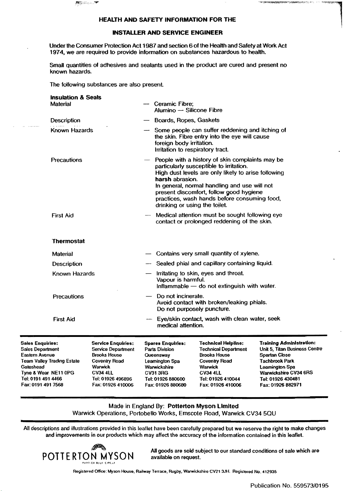
Supplied By www.heating spares.co Tel. 0161 620 6677
HEALTH
AND
SAFETY INFORMATION FOR
THE
INSTALLER
the Consumer Protection
Under
197
4.
we are required
Small
quantities of adhesives and sealants used in the product are cured and present no
to
provide information
Act
AND
1987
and section 6
SERVICE ENGINEER
of
the Health and Safety at Work Act
on
substances hazardous
to
health.
known hazards.
The following substances are
also present.
Insulation & Seals
Material
Description
Known Hazards
Ceramic Fibre;
Alumino
- Silicone Fibre
Boards, Ropes, Gaskets
Some people can suffer reddening and itching
the skin. Fibre entry into the eye will cause
Precautions
foreign
Irritation to respiratory
People with a history
particularly
High dust
harsh
body
irritation.
tract
of
susceptible to irritation.
levels are only likely
abrasion.
skin complaints may be
to
arise following
In general, normal handling and use will not
present discomfort. follow
good hygiene
practices, wash hands before consuming food,
First Aid
drinking or using the
Medical attention· must be sought following eye
contact
or
prolonged reddening of the skin.
to!let.
of
Thermostat
Material
Description
Known Hazards
Precautions
First Aid
Sales Enquiries:
Sales Department
Eastem
Avenue
Team Valley Trading Estate
Gateshead
Tyne&
Wear
NE11
OPG
Tel:0191491
Fax:
0191
491
4466
7568
Warwick Operations, Portobello Works. Emscote Road, Warwick
Service Enquiries:
SeMce Department
House
Brooks
01926
01926
Road
496896
410006
Coveoll'y
Warwick
CV344ll
Tel:
Fax:
Made in England
Contains very
small quantity
of
xylene.
Sealed phial and capillary containing liquid.
Irritating
to
skin, eyes and
throat
Vapour is harmful.
Inflammable
Do
not incinerate.
do
not extinguish with water.
Avoid contact with broken/leaking phials.
Do not purposely puncture.
Eye/skin
contact. wash with clean water, seek
medical attention.
Spares
Enquiries:
Parts
Division
Oueeosway
Leamington Spa
Warwickshire
CV313RG
Tel:
01926 880600
Fax:
01926
880680
By:
Potterton
Technical Helpline:
Technical Department
Brooks House
Coveoll'y
Warwick
CV34
Tel: 01926 410044
Fax:
Myson
Road
4ll
01926
Limited
410006
CV34
Training Administration:
Unit 5, Titan Business Centre
Spartan Close
Tachbrook Park
Leamington Spa
Warwickshire CV34 6RS
Tel:
01926
Fax: 01926 882971
430481
50U
All descriptions
POTTERTON
and
illustrations provided in this leaflet have been carefully prepared but
and improvements in
~
Registered Office: Myson
our
products which
MYSON
~.Railway
may
affect
the
accuracy of
All
goods
are sold subject to
on
available
Terrace, Rugby. Warwickshire CV21 3JH. Registered No. 412935
request.
we
reserve
the
information contained in this leaflet.
our
standard conditions
the
right to make changes
of
Publication No. 559573/0195
sale which are
 Loading...