

Page 1

OPEN
control
End User Manual
DOCUMENT NUMBER: 4602H
RELEASE REF.:
EDITION: 00
AUTHOR: Prima Electro S.p.A.
DATE: June 2013
PRIMA ELECTRO reserves the right to modify and improve the product described in this manual at any
time and without prior notice. The application of this manual is under customer responsibility. No
further guarantees will be given by PRIMA ELECTRO, in particular for any possible faults, incompleteness
and/or difficulties in the operation. In no event will PRIMA ELECTRO be responsible or liable for indirect
or consequential damages that may result from the use of such documentation.
COPYRIGHT 2013- Prima Electro S.p.A.
All rights reserved. Reproduction, use or disclosure to third parties without express authority is strictly
forbidden.
Page 2

Prima Electro S.p.A. OPENcontrol – End User Manual
Edition
Date
Notes
Author
00
14/06/2013
First DRAFT
Prima Electro S.p.A.
45004602H 2
Page 3

Prima Electro S.p.A. OPENcontrol – End User Manual
Contents
1. Features and specifications ............................................................................................................ 7
Reading keys and security instructions ................................................................................................................................. 7 1.1
General .......................................................................................................................................................................................... 7 1.2
Hardware structure ................................................................................................................................................................... 8 1.3
1.3.1 Operator Panel ............................................................................................................................................ 9
1.3.2 OPENconsole and OPENconsole COMPACT ................................................................................................ 9
WinNBI Interface Software.................................................................................................................................................... 10 1.4
1.4.1 Connection between the WinNBI and the CNC ........................................................................................ 11
1.4.2 Common features of the WinNBI applications ......................................................................................... 12
2. System Start-up ............................................................................................................................. 14
System Power Up ..................................................................................................................................................................... 14 2.1
System Shut Down ................................................................................................................................................................... 14 2.2
Diagnostic Screens ................................................................................................................................................................... 16 2.3
Switching the System in Special Operating Modes........................................................................................................... 17 2.4
Selection of the Operating Mode ......................................................................................................................................... 18 2.5
3. User Interface ................................................................................................................................ 21
The Screen ................................................................................................................................................................................. 21 3.1
The Keyboard ............................................................................................................................................................................ 21 3.2
The Control Panel .................................................................................................................................................................... 21 3.3
The ProcessController ........................................................................................................................................................... 22 3.4
3.4.1 Title bar ..................................................................................................................................................... 23
3.4.2 Menu bar .................................................................................................................................................. 23
3.4.3 Tool bar ..................................................................................................................................................... 23
3.4.4 Operator Panel bar ................................................................................................................................... 24
3.4.5 OEM Operator Panel ................................................................................................................................. 25
3.4.6 Screen layouts ........................................................................................................................................... 26
3.4.7 SoftKey bar ................................................................................................................................................ 26
3.4.8 Main video screen osai_p6a.qv ................................................................................................................ 27
CNC Status Area ...................................................................................................................................................................... 28 3.5
Flags Area ................................................................................................................................................................................... 30 3.6
3.6.1 Axes positions and origin area .................................................................................................................. 31
3.6.2 Feed and overrides Area ........................................................................................................................... 32
3.6.3 Selected Tools Area ................................................................................................................................... 33
3.6.4 G and M functions Area ............................................................................................................................ 34
45004602H 3
Page 4

Prima Electro S.p.A. OPENcontrol – End User Manual
3.6.5 Part program data area ............................................................................................................................. 34
Keyboard Commands .............................................................................................................................................................. 35 3.7
3.7.1 Additional information windows .............................................................................................................. 35
Panels for Command and data input.................................................................................................................................... 36 3.8
3.8.1 General rules on the input windows ......................................................................................................... 36
3.8.2 The ProcessController soft-keys ............................................................................................................... 37
3.8.3 Multiple connection, CNC selection .......................................................................................................... 40
3.8.4 MDI Panel functions .................................................................................................................................. 54
Operator Consoles .................................................................................................................................................................. 55 3.9
3.9.1 Keys and functions of the OPENconsole COMPACT Operator Panel ........................................................ 55
3.9.2 Keys and functions of the OPENconsole COMPACT Operator Panel ........................................................ 57
4. Establishing origins and homing the axes .................................................................................... 58
General ........................................................................................................................................................................................ 58
4.1
Axis homing procedure ........................................................................................................................................................... 58 4.2
Definition of the origins .......................................................................................................................................................... 59 4.3
4.3.1 Manual setting of the absolute origin....................................................................................................... 60
4.3.2 Automatic set of the absolute origin ........................................................................................................ 61
Axes and part origins ............................................................................................................................................................... 64 4.4
5. Axes jogging and Stop functions .................................................................................................. 66
JOG .............................................................................................................................................................................................. 66 5.1
5.1.1 Continuous jog .......................................................................................................................................... 67
5.1.2 Incremental JOG ....................................................................................................................................... 68
Manual Feedrate change .......................................................................................................................................................... 68 5.2
Hold entry and JOG return on the profile ........................................................................................................................ 68 5.3
Spindle Speed Override .......................................................................................................................................................... 70 5.4
Stop functions ............................................................................................................................................................................ 70 5.5
5.5.1 Reset ......................................................................................................................................................... 70
5.5.2 Hold ........................................................................................................................................................... 71
Emergency Stop ........................................................................................................................................................................ 71 5.6
Active reset ................................................................................................................................................................................ 71 5.7
Removing the tool after an Emergency ............................................................................................................................... 74 5.8
6. Part Program Management .......................................................................................................... 77
Main Video Screen .................................................................................................................................................................... 77 6.1
Selection of an item .................................................................................................................................................................. 78 6.2
Multiple selection ...................................................................................................................................................................... 78 6.3
Creation of a new Part Program .......................................................................................................................................... 79 6.4
Creation of a new Directory ................................................................................................................................................. 79 6.5
File copy and directory............................................................................................................................................................ 80 6.6
45004602H 4
Page 5

Prima Electro S.p.A. OPENcontrol – End User Manual
Delete a directory or a file..................................................................................................................................................... 80 6.7
Change the name of a file or a directory ........................................................................................................................... 81 6.8
Writing and editing a Part program ..................................................................................................................................... 81 6.9
Enabling a Part-Program for the execution ........................................................................................................................ 82 6.10
Disabling the Part-Program selected ................................................................................................................................... 82 6.11
Program Management Configuration ................................................................................................................................... 83 6.12
Logical drive configuration ..................................................................................................................................................... 83 6.13
6.13.1 Adding a logical drive ................................................................................................................................ 84
6.13.2 Removing a logical drive ........................................................................................................................... 84
6.13.3 Showing logical drive path ........................................................................................................................ 84
Four Windows Display (Quad View) .................................................................................................................................. 85 6.14
7. Part Program execution ............................................................................................................... 86
Part program execution .......................................................................................................................................................... 87 7.1
7.1.1 Selecting and activating a part program ................................................................................................... 87
7.1.2 Automatic execution ................................................................................................................................. 87
7.1.3 Block-by-block execution .......................................................................................................................... 87
7.1.4 Multiblock retrace..................................................................................................................................... 88
Executing blocks from the keyboard ................................................................................................................................... 89 7.2
7.2.1 MDI execution without an active part program ....................................................................................... 89
7.2.2 MDI execution with an active part program ............................................................................................. 89
7.2.3 Executing part of a part program .............................................................................................................. 90
Modifying blocks in BLK/BLK mode..................................................................................................................................... 90 7.3
Strings search ............................................................................................................................................................................. 91
7.4
Feedrate Override .................................................................................................................................................................... 91 7.5
Spindle feedrate override ....................................................................................................................................................... 91 7.6
Rapid Feedrate Override ........................................................................................................................................................ 92 7.7
Execution in Dry Run mode .................................................................................................................................................... 92 7.8
Memory Search ......................................................................................................................................................................... 92 7.9
7.9.1 Automatic Search ...................................................................................................................................... 93
7.9.2 Search for a pre-set block ......................................................................................................................... 93
Restart a working cycle ........................................................................................................................................................... 94 7.10
Searching Mode ......................................................................................................................................................................... 94 7.11
8. Using Tables .................................................................................................................................. 96
Enabling Table Editor ............................................................................................................................................................... 96 8.1
Origin Table ............................................................................................................................................................................. 102 8.2
Tool Table ................................................................................................................................................................................ 104 8.3
Tool Offset Table ................................................................................................................................................................... 106 8.4
User Table ................................................................................................................................................................................ 110 8.5
45004602H 5
Page 6

Prima Electro S.p.A. OPENcontrol – End User Manual
9. The Table Builder ....................................................................................................................... 111
General ...................................................................................................................................................................................... 111 9.1
Origin table customization ................................................................................................................................................... 114 9.2
Tool Table customization ..................................................................................................................................................... 119 9.3
Table Offset Customization ................................................................................................................................................. 124 9.4
User Table customization ..................................................................................................................................................... 129 9.5
Translation of the variable names....................................................................................................................................... 136 9.6
Configuration file .................................................................................................................................................................... 137 9.7
10. Tool Management ...................................................................................................................... 138
General ...................................................................................................................................................................................... 138 10.1
Tool Pre-setting ...................................................................................................................................................................... 138
10.2
10.2.1 Manual Tool pre-setting ......................................................................................................................... 138
10.2.2 Manual pre-setting of the tool length mounted on the spindle ............................................................. 141
10.2.3 Automatic pre-setting of the tool mounted in the spindle ..................................................................... 142
11. Machine Plot ............................................................................................................................... 143
General ...................................................................................................................................................................................... 143 11.1
Machine Plot Interface ........................................................................................................................................................... 143 11.2
Machine Plot Configuration ................................................................................................................................................. 147 11.3
Profile Drawing ....................................................................................................................................................................... 151 11.4
Drawing a 3D Profile ............................................................................................................................................................. 153 11.5
Checking the Profile ............................................................................................................................................................... 154 11.6
Drawing the disconnected axes profile (DRY RUN) .................................................................................................... 157 11.7
12. System History ............................................................................................................................ 158
General ...................................................................................................................................................................................... 158 12.1
System History Interface ...................................................................................................................................................... 158 12.2
13. Appendix A .................................................................................................................................. 164
Error Messages ........................................................................................................................................................................ 164 13.1
45004602H 6
Page 7
Prima Electro S.p.A. OPENcontrol – End User Manual
WARNING! Dangerous Voltage: This symbol is associated with dangerous high voltages
that could damage the system, the equipment and the operators.
WARNING! Danger: This symbol is associated with facts and circumstances that could
damage the system, the equipment and the operators.
NOTES: This symbol is used for operations that have to be executed with great care in
order to ensure their successful completion.
1. Features and specifications
Reading keys and security instructions 1.1
ATTENTION! To use the system in a correct manner, follow the instructions provided in this manual and
pay special attention to the symbols below:
General 1.2
OPENcontrol is a family of state-of-the-art numerical controls, designed to meet a vast range of standard
and non-standard application requirements. The most powerful model can manage up to 64 digital axes.
The OPENcontrol systems can be installed on many types of machine: milling machines, grinding
machines, wood-, glass- and marble-working machines, oxygen cutters, etc. Thanks to the “open”
Hardware and Software architecture, the systems are particularly suitable for both standard and for
those applications requiring special functions. OPENcontrol allows the manufacturer to customize the
system to integrate with their specific application requirements.
The OPENcontrol systems are based on the most advanced technologies; from the hardware components
to the powerful Operating System (multitasking, real time, event driven) complete with either a local or
networked graphic interface, that makes the OPENcontrol system one of the most important CNCs. The
powerful and sophisticated functions typical of numerical control, can be combined with a user friendly
interface, configurable according to the MTB’s requirements. This interface is named “WinNBI”
(Windows Network Based Interface) and is displayed on the operator panel connected to the CNC.
There are several HMI types to match with the OPENcontrol, from the simple industrial monitor up to the
more advanced Operator Panel. This manual describes the user interface provided by the OPENconsole
Operator panel and the WinNBI application graphical software. In the following pages, there is an
overview of the configuration to which this manual refers.
For any additional information and a complete evaluation of all the OPENcontrol hardware configuration,
refer to the manuals below:
“OPENcontrol – Software Installation Manual” code 45006692G.
“OPENcontrol – Installation Guide” code 45006652F.
45004602H 7
Page 8
Prima Electro S.p.A. OPENcontrol – End User Manual
Hardware structure 1.3
The OPENcontrol systems are made up of a number of modules that can be combined in different ways
according to the requirements. Usually, the system has an operator panel used to display the data and to
handle commands to be sent to the CNC.
Only skilled operators together with the MTB can open the operator panel and the basic
unit for “service” reasons.
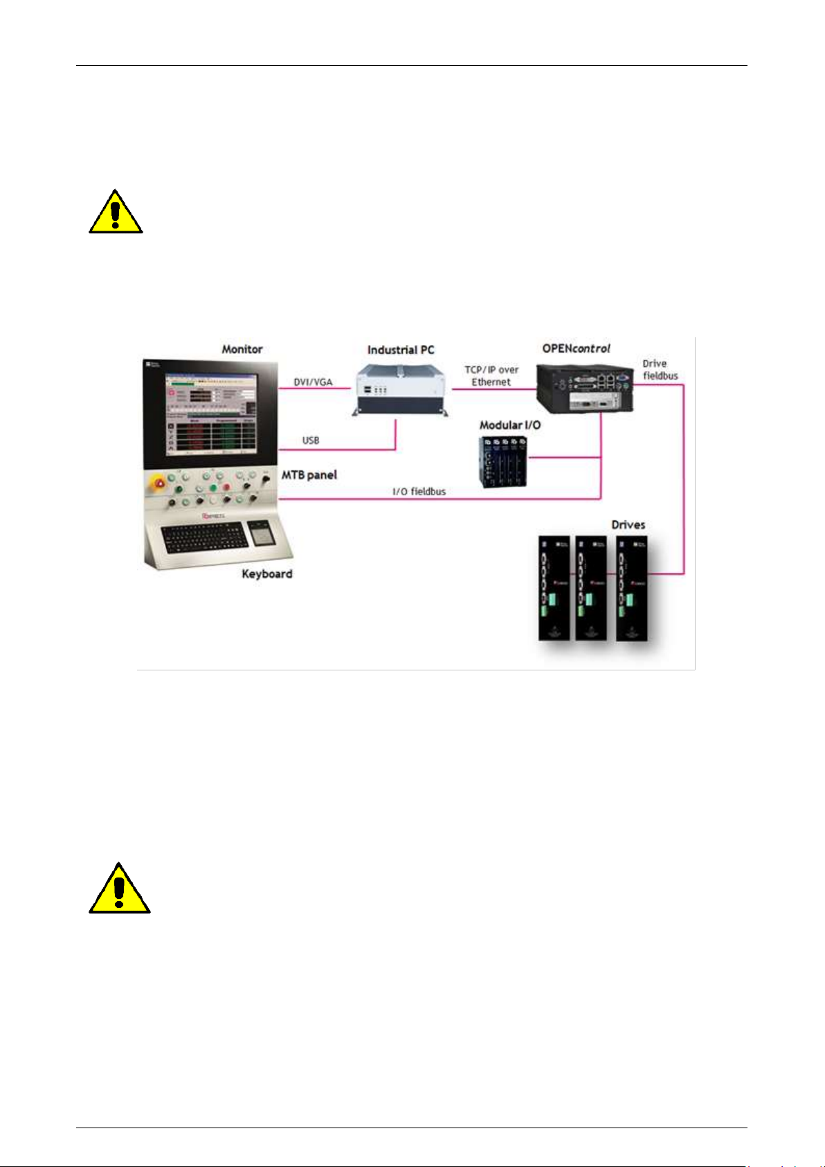
This manual explains how to use the OPENcontrol CNCs combined with the OPENconsole operator panel
as shown below.
In this configuration the OPENcontrol Control Unit is connected on the network to an industrial PC
dedicated to the graphical user interface. The control unit is therefore dedicated to the real-time
software, while the data is displayed on the industrial PC on the OPENconsole Operator Panel. The other
devices, such drives and I/Os, are connected to the Control Unit.
In other configurations, the user interface software runs on the control unit without using an industrial
PC between the control unit and the operator panel.
This manual describes the use of standard video screen layouts provided by Prima Electro
with the product software release. The structure of the video screen layouts can be
changed by the MTB, and may therefore appear to the end user in a different way. In this
case, the MTB will describe the functionality of the customized screen layouts.
45004602H 8
Page 9
Prima Electro S.p.A. OPENcontrol – End User Manual
1.3.1 Operator Panel
The Operator Panel (or front panel) is the interface device between the system and the operator.
In all versions, the Operator Panel is equipped with a LCD monitor, a standard USA-ASCII keyboard with
function buttons that work as softkeys.
It offers the most up to date Man-Machine interface techniques together with ease of use, its main
functions are:
introduction of operating commands.
introduction of start, stop and reset commands.
the data input using the keyboard
software and data entry (part program, software options, etc.), using USB connected devices.
display of the data and all the system operating conditions.
control of the CNC and PC ambient.
This manual deals with the OPENconsole operator panel use and the WinNBI graphical user interface by
Prima Electro.
1.3.2 OPENconsole and OPENconsole COMPACT
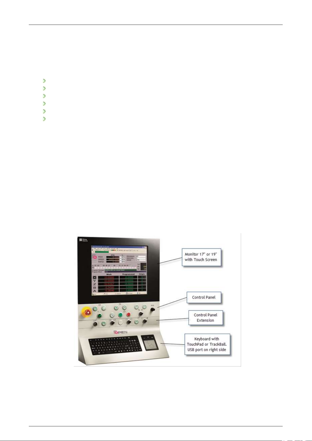
The OPENconsole operator panel offers great modularity and an innovative design. The panel consists of
independent modules that can be assembled together to obtain the ideal configuration match the
specific application requirement. The Control Panel exchanges data using an EtherCAT fieldbus. The
panel is equipped with a silicon rubber keyboard, Windows standard, that is supplemented by a Touch
Pad or Track-Ball unit. The 17” or 19” Monitor, has a resistive integrated Touch Screen. Both the monitor
and the keyboard can be connected directly to the CNC or to the interface PC (if this is provided in the
system configuration).
Figure 1: OPENconsole configuration with Monitor, Control Panel, Control Panel Extension
and Keyboard with TouchPad
45004602H 9
Page 10
Prima Electro S.p.A. OPENcontrol – End User Manual
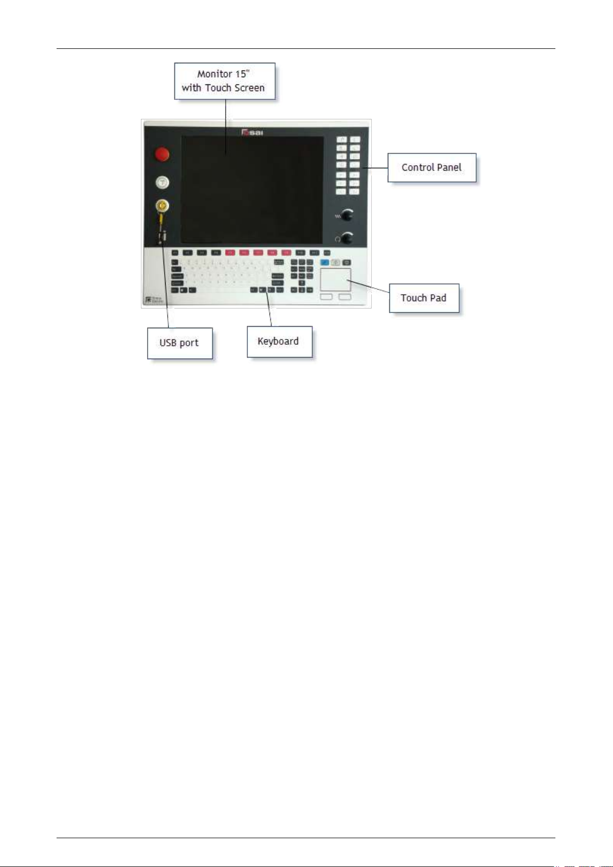
Figure 2: OPENconsole COMPACT - all HMI elements in one module
WinNBI Interface Software 1.4
The WinNBI graphics suite (Windows Network Based Interface) consists of several different applications
or independent HMI utilities, each dedicated to a specific function. These applications allow the
complete management of the machine tool. The applications (standard or optional) are for users having
different requirements (end user, MTB, service engineer). This manual describes the WinNBI utilities
used by the end user:
ProcessController Data display and commands for the CNC.
This is the main WinNBI application which displays all the CNC data: axes position,
speed, active functions, program lines etc. and also allows the sending of
commands and parameters to the CNC. The Process Controller is supplied with
some standard video screens to manage the machine in manual and automatic
mode. In addition the optional Layout Builder ambient allows the screen content
to be adapted to suit the exact requirements of the application
Therefore, the ProcessController can present a graphic interface completely
different from the standard one supplied and documented by Prima Electro.
BootController Numerical Control boot controller.
It displays the messages from the CNC during the boot stage. It also allows the
system software restart and setting of the operating state that the CNC must be in
for machining, tuning and service.
45004602H 10
Page 11

Prima Electro S.p.A. OPENcontrol – End User Manual
TableEditor Data table editor
It allows display, entry and modification of some parameters, in particular:
origins
tools
tool offsets
user tables
tool magazines
tool data base
The TableBuilder is part of the TableEditor allowing customisation of the data and
the data display within the same tables. For details see chapters 8 and 9.
System History This is a standard feature that stores in a file all the diagnostic messages produced
by the system in case of malfunction or incorrect operation, together with time
and date. It is a useful tool for fault diagnosis.
1.4.1 Connection between the WinNBI and the CNC
As described in the previous paragraphs, the WinNBI applications can be installed on both the PC
dedicated to the HMI and the control unit. In both cases, the applications connect to a data server in the
control unit. The connection between the WinNBI Application and the NC, is always done via the
network. The network will be virtual for the WinNBI locally installed on the CNC and real in case of the
PC installation on the network. In all the WinNBI applications, the user can select the numerical control
to which the application has to connect. The connection status is displayed in a dedicated status bar.
45004602H 11
Page 12
Prima Electro S.p.A. OPENcontrol – End User Manual
1.4.2 Common features of the WinNBI applications
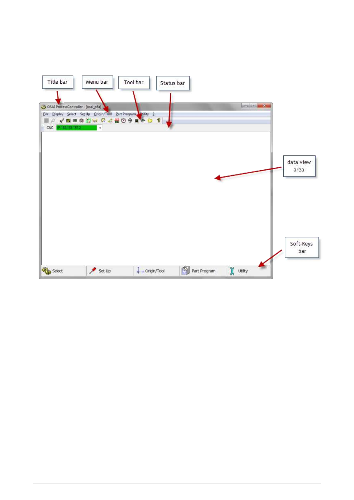
Even if activated separately, the WinNBI applications are designed to offer the same graphic structure
and common elements for ease of use. The basic graphic structure of a WinNBI application is as follows:
Title bar: Shows the name of the application and in some cases the name of the document
(typically the file name) to which the application refers for the data display.
Menu Bar: Contains the main menu commands. These commands open a scroll-down menu
listing a group of commands or a data insertion panel. The menu bar always
contains all the entries in the Softkey bar together with other entries less used by
the operator.
Tool Bar: Contains the buttons enabling the most used application functions. These can be
direct or indirect commands. Every WinNBI application can have several or nontoolbars.
Status Bar: Displays the name of the Numerical Control to which the application is connected
and the connection status via the virtual or real network.
Data view area: This is the area where the application displays the information and the graphic
objects dedicated to the specific functions required by the application. Each
WinNBI application has data and control elements of different types in this area.
45004602H 12
Page 13

Prima Electro S.p.A. OPENcontrol – End User Manual
Softkey bar: It is a bar that, in all applications, has 5 buttons that can be enabled using the
mouse or touch Screen. For quicker activation, the buttons are associated with the
function buttons F6 and F10 of the operator panel keyboard. These 5 buttons open
the scroll-down menus containing the most used commands (see also Menu bar
description).
In some application, the display of the field described can be customized. Their presence on the video
depends on the settings made by the OEM and by the final user.
45004602H 13
Page 14

Prima Electro S.p.A. OPENcontrol – End User Manual
2. System Start-up
To turn the system on and off, comply with the machine manufacturer’s instructions. To
turn off the Numerical Control, follow the shut-down procedure described below.
System Power Up 2.1
The system is powered up when power is supplied to the central unit and the front panel, typically this is
done by operating the machine’s main power switch. Since most of the system software is stored on the
hard disk, all the software that remains resident for the numerical control operation is automatically
uploaded from the hard disk at system boot.
The BootController is a utility of the WinNBI graphic interface that checks and manages the CNC power
up. Using this application, it is possible to choose the CNC operating mode and to check the messages
generated by the CNC when powering up. The main working modes of the CNC are “Normal”,
“Emergency”, “Setup” and “Service” are defined as “stable”. Each mode has a specific function (for
details see the paragraph “Switching the system on in special operation modes”. The other modes, e.g.,
“HW boot” and “SW boot”, are transitory and lead to one of the stable modes. The BootController utility
displayed by the OPENconsole Operator Panel, in the Windows ambient, can be manually enabled or
automatically launched at power up. This behaviour depends on the choices made by the OEM when
installing WinNBI.
By default, the BootController, after connecting to the CNC and verifying that a stable mode has been
established, automatically launches the ProcessController application for the system management.
System Shut Down 2.2
The CNC must always be shut down using the “Controlled shut down” procedure that closes all open
sessions. This ensures the integrity of the data contained in the user, OEM or system files that, when
shutting down, could still be open for writing.
Controlled shut down can be initiated during all working stable modes of the CNC. It is done using the
BootController application.
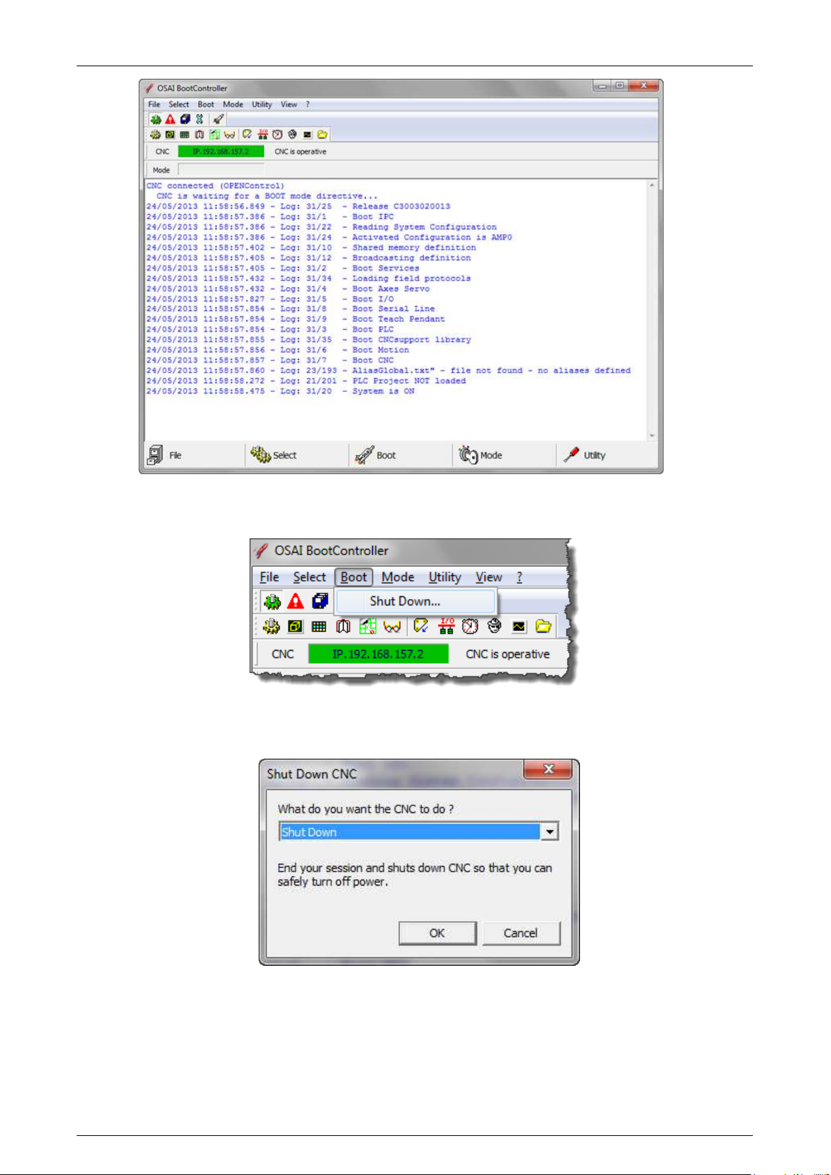
The procedure is:
With the system on in one of the four stable operating modes:
If disabled, enable the BootController application
45004602H 14
Page 15
Prima Electro S.p.A. OPENcontrol – End User Manual
and select the “Shut Down” command from the “Boot” menu.
In the window, select the “Shut Down” command and confirm with the “OK” button
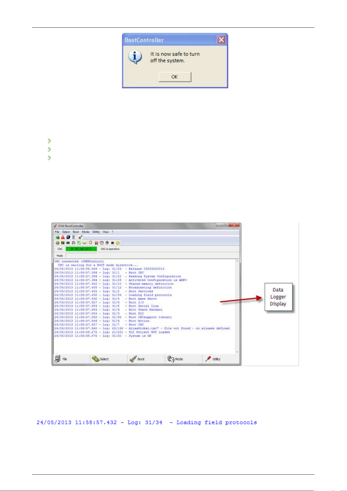
when shut-down is completed, the following message appears, indicating that the CNC can be turned
off.
45004602H 15
Page 16
Prima Electro S.p.A. OPENcontrol – End User Manual
Diagnostic Screens 2.3
The control starts the diagnostic phase at boot up during which the hardware and software modules of
the system are checked. The modules are tested in the following order:
basic hardware (CPU, ROM, RAM, keyboard and disk)
modules and additional devices
numerical control software
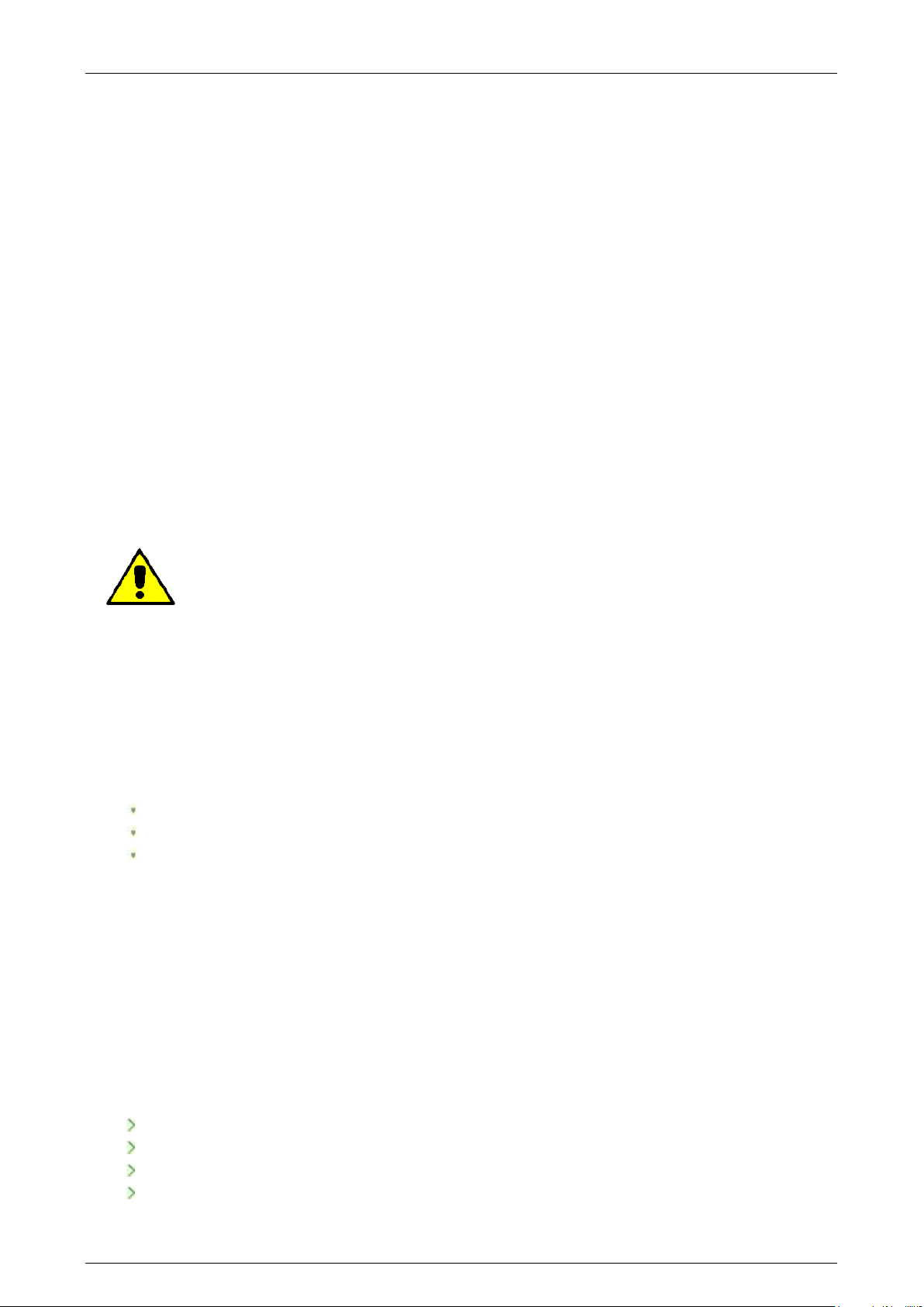
The messages generated from the CNC diagnostics are displayed in the main window of the
BootController application (Data Logger Display).
If the system is powering up, the messages are displayed as they are generated, but the same messages
are recorded by the CNC and are visible in the Data Logger Display at any time, even when the boot
phase of the CNC is finished.
The messages generated by the diagnostics are listed according to the test results and change according
to the hardware and software system configuration, both in quantity and meaning.
Usually the messages are divided in several parts as the example below:
45004602H 16
Page 17
Prima Electro S.p.A. OPENcontrol – End User Manual
From left to right, the message contains the following elements:
Date and Time Are the date and time of the message generation, with mill-second precision.
Ambient Indicates what part of the CNC generates it (e.g., “Log”).
Message Code Two numbers separated by a slash. The numbers identify the message (in this
example "31/34"). The first number is the "Class" of the message, identifying a
group or category of messages. The second number is the message "Code". Codes
within a class are consecutive numbers starting from 1. The whole Class+Code
group uniquely identifies a message or an error code of the OPENcontrol.
Message Text This column contains a brief description of the type of operation performed, the
test passed by a device or the software section initialized. The message may be an
error message if the operation has failed. The message in this example is "Loading
field protocols."
Appendix A describes all the messages in detail and possible corrective actions.
When the CNC detects a non-critical error, it indicates it through the message in the Data
Logger and continues powering up the system. These errors are recorded in the “SW0”
variable, accessible to the machine logic. The subsequent behaviour of the system
depends on the machine logic defined by the OEM.
For additional details on the non-critical errors, see the documentation of the SW0
variable in the “OPENcontrol – Application Manual” code 45006962W.
Switching the System in Special Operating Modes 2.4
With the OPENcontrol system, it is possible to execute power on sequences different to the default.
These power up sequences put the CNC into special operating modes, activating only parts of the
software system, allowing execution of such basic operations as:
software installation or update
calibration
system configuration
Some of these modes are essential, for example, to remove user errors in the characterisation that
prevents the CNC from starting properly.
The four OPENcontrol operating modes are:
Normal Mode: it is the standard boot mode of the CNC, for the Part Program management and
execution, axes movement etc.
Emergency Mode: the CNC works as a Server and only certain operations can be done, the main ones
are:
changing the AMP characterization using the ODM utility
reset, save and restore the retentive memory via BootController
reset of the CNC message history via the CNC System History utility
CNC file management
45004602H 17
Page 18
Prima Electro S.p.A. OPENcontrol – End User Manual
Setup Mode: the CNC works as a File Server. In this mode, using the Security application, it is possible to
upload the basic software, fixup or options to the CNC. It is also possible to save the CNC mass memory,
to manage the security levels and option enabling (PAK) and to manage surface checks of the CNC disks,
etc.
Service Mode: the CNC executes only the first boot stage of the CNC to initialize the axes control
software. This mode is used for the calibration of the digital drives via the ODM utility.
The Emergency, Setup and Service modes can be set only via the BootController utility. If nothing is
done with the BootController, the CNC will automatically select Normal mode.
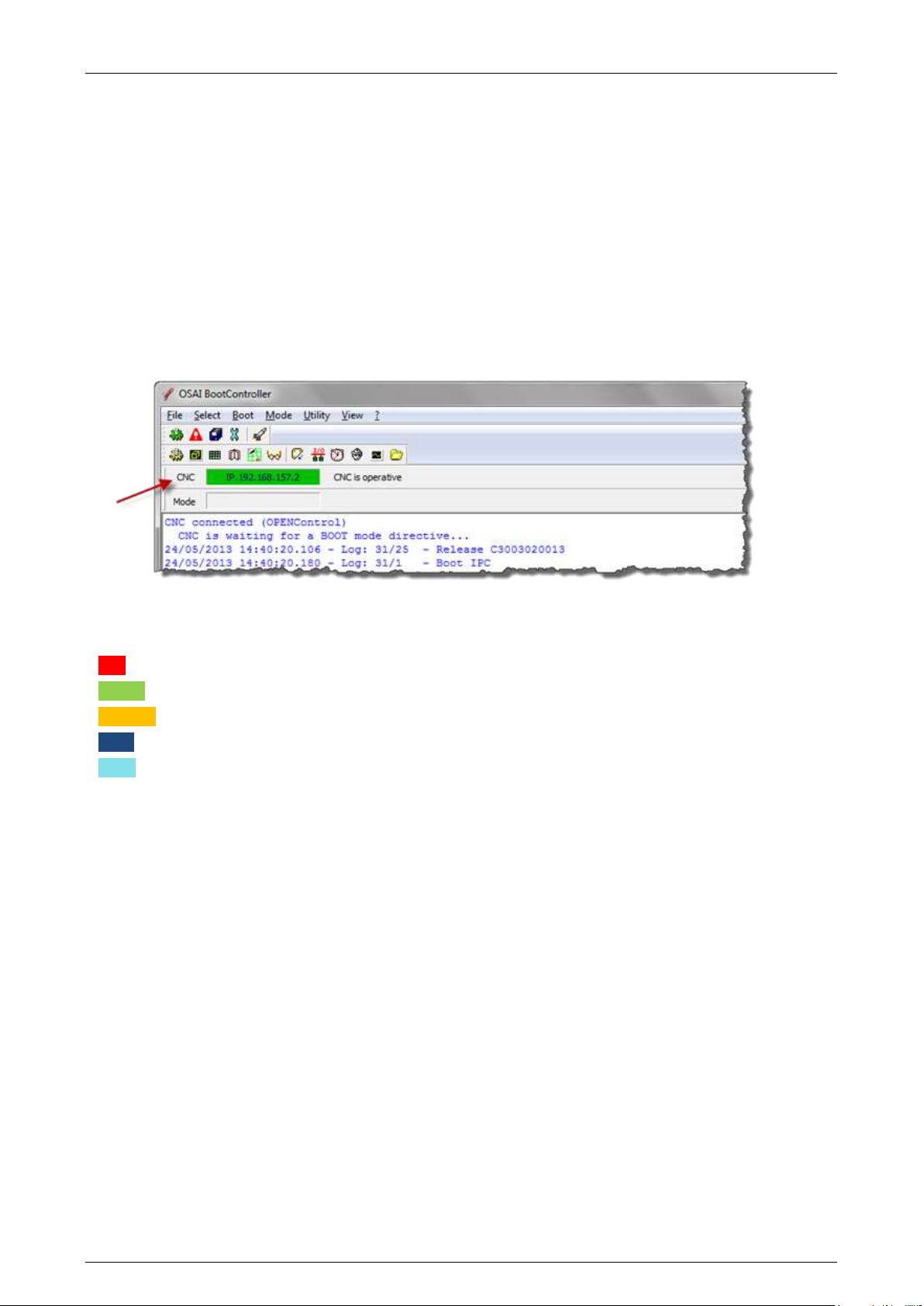
All the WinNBI application indicate the operating mode of the CNC via a status bar that displays the
name of the numerical control connected:
The background of the field containing the CNC name changes according to the status of the connection
between the WinNBI and the CNC. The colours used and their meanings are:
RED CNC not connected. Connection in progress.
GREEN CNC connected. CNC in “Normal” mode
ORANGE CNC connected. CNC in “emergency” mode
BLUE CNC connected. CNC in “Setup” mode
CYAN CNC connected. CNC in “Service” mode
At the end of the CNC boot phase, in the working mode Normal or Emergency, if the option A03 is
enabled on the system (see Application Security WinNBI), the BootController automatically starts the
ProcessController application.
The ProcessController is the main application for numerical control management. The automatic start-up
of ProcessController can be disabled via the "NBIconfig" configurator of the WinNBI.
Selection of the Operating Mode 2.5
To select the boot-up operating mode of the CNC, the BootController is used. The procedure is the same
for all the operating modes described in the previous paragraph.
Selection of the operating mode with system on
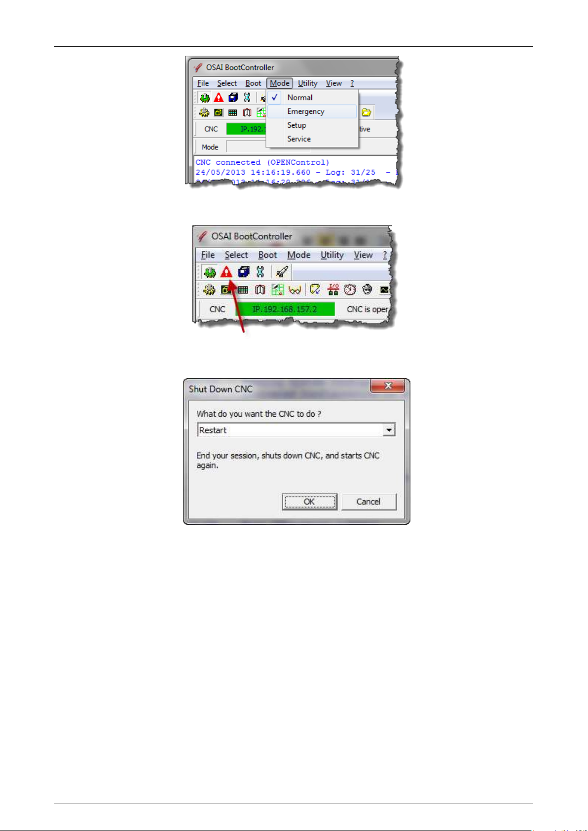
To enable an operating mode, i.e., Emergency, select “Emergency” using the “Mode” menu
45004602H 18
Page 19
Prima Electro S.p.A. OPENcontrol – End User Manual
or with the dedicated button in the BootController toolbar.
After selection, reboot the CNC using the “Shut Down” command from the “Boot” menu entry.
The system re-executes the boot phase, as if it had been turned off and on, and enters the EMERGENCY
boot mode identified by the orange colour in the status bar.
Selection of the operating mode with the system off
Turn the system on. After the first hardware boot stage, the CNC waits for 30 seconds, for the selection
of the operating mode from the Boot Controller. During this time it is possible, to select the desired
mode using the buttons on the tool-bar. The CNC will continue the boot with the selected mode. If no
selection is made, the CNC, continues to the Normal mode.
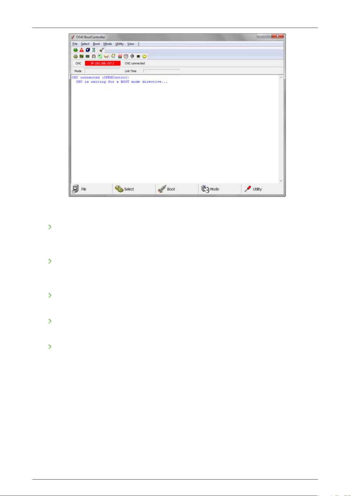
When the BootController is connected to a CNC waiting for the selection of the operating mode, the
following page is displayed:
45004602H 19
Page 20
Prima Electro S.p.A. OPENcontrol – End User Manual
In emergency status the following WinNBI applications can be used:
SECURITY
Manages the security levels of the system for different user and installation levels. More
information about this utility can be found later in this manual.
SYSTEM HISTORY
Utility for viewing / printing / deleting of the archived errors and system messages displayed
during the machine operation.
FILEBROWSER
Management of the CNC’s and the PCs OSAI file system.
ODM
Definition and change of the system configuration.
TABLE EDITOR
Management of the system’s data tables (Tools, Offset, Origins and User). In Emergency mode, it
is possible to work only on the tables file, not on the retentive memory files.
45004602H 20
Page 21
Prima Electro S.p.A. OPENcontrol – End User Manual
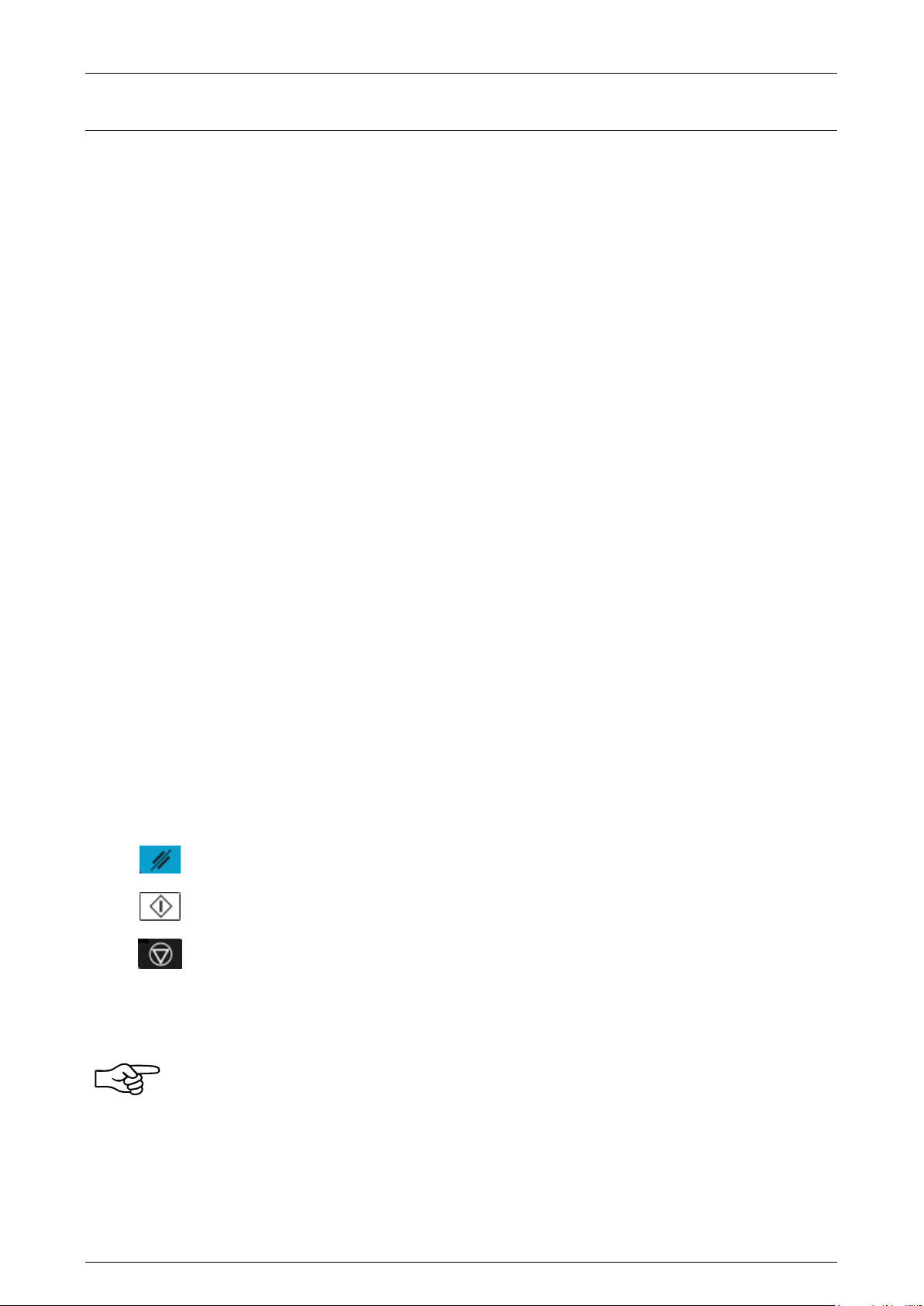
The RESET button interrupts both the part program being executed and any
active function.
The CYCLE START button initiates axes movements and other commands in both
manual and automatic mode.
The CYCLE STOP button temporarily stops the active functions. For instance it
stops the part program execution with a controlled deceleration of the axes.
After a CYCLE STOP the operation can be restarted.
3. User Interface
The system displays data and information on the screen to start the communication, then the operator
introduces commands and data. All these operations take place on the operator panel. The keyboard,
video and the softkeys of the panels " OPENconsole " and "OPENconsole COMPACT" are described here.
The user interface is the means by which the operator communicates with the system.
The Screen 3.1
The screen is the means by which the system communicates with the operator, sharing all information
concerning the functioning, the data associated with the operations carried out, the data entry requests,
etc.
The screen can have a Touch functions to select field and graphic areas, to enable commands, etc.
With the OPENconsole Operator Panel the information is displayed on a 17” or 19” colour screen with
the Touch Screen option and 1280x1024 resolution. The COMPACT OPENconsole Operator Panel is
equipped with a 15’’ monitor with 1280x1024 resolution and Touch Screen option.
The Keyboard 3.2
The OPENconsole and OPENconsole COMPACT Operator Panels have a 101-key U.S. keyboard.
The function buttons from F5 to F10 have a special function when the panel is used with the Prima
Electro HMI software. The WinNBI, uses the function buttons for softkey activation. The F4 button is used
for the selection of the video screen to display.
The Control Panel 3.3
The two Operator Panels have a section (Control Panel) used to send the operating instructions to the
numerical control. The buttons provide the following functions:
More detailed information on each button will be provided later in this manual.
The functions of the buttons described here those provided as standard by the system.
However, they may be changed through the machine logic written by the machine tool
builder. Refer to the MTB documentation.
45004602H 21
Page 22
Prima Electro S.p.A. OPENcontrol – End User Manual
The ProcessController 3.4
The ProcessController utility of the WinNBI displays and manages both axes movements and part
programming of the CNC. For general features of the WinNBI applications, refer to Ch.1-“Features and
specifications”.
For proper use of the ProcessController, it is important to understand the concept of “process”.
“Process” (or “channel”) means the management of a machine tool, i.e., the control of the axes, the
part program execution, the enabling and disabling of the machine logic control, etc.
More generally, process can also refer to a support activity for the machine tool, such as the tool
change, management of part loading and unloading, calculations, statistics, reports, etc.
The term multiprocess represents one of the most important features of the OPENcontrol numerical
controls. A single CNC can manage un to 24 different processes. The processes work simultaneously,
each executing a part program independent of the others. If the systems controlled by the individual
processes must be synchronized, they can be controlled more quickly and with greater flexibility than
with separate control systems. The standard screens provided by Prima Electro with the
ProcessController, display the data of only one process, so that they can be used on any machine. The
standard screen can be used for multiprocess/mono-process systems. For the multiprocess systems, it is
enough to select the desired process to ensure that the data on the screens are automatically updated
with the selected process.
This manual describes the use of the standard screens provided by Prima Electro the
software product release. The layout of the screens can be changed by the OEM and can
then appear in a very different way to the end user. In this case the OEM describes the
functionality of the customised screens.
Even if the content of the screen changes, the commands and the data-entry enabled with the data
entry menu or with the softkeys remains unchanged.
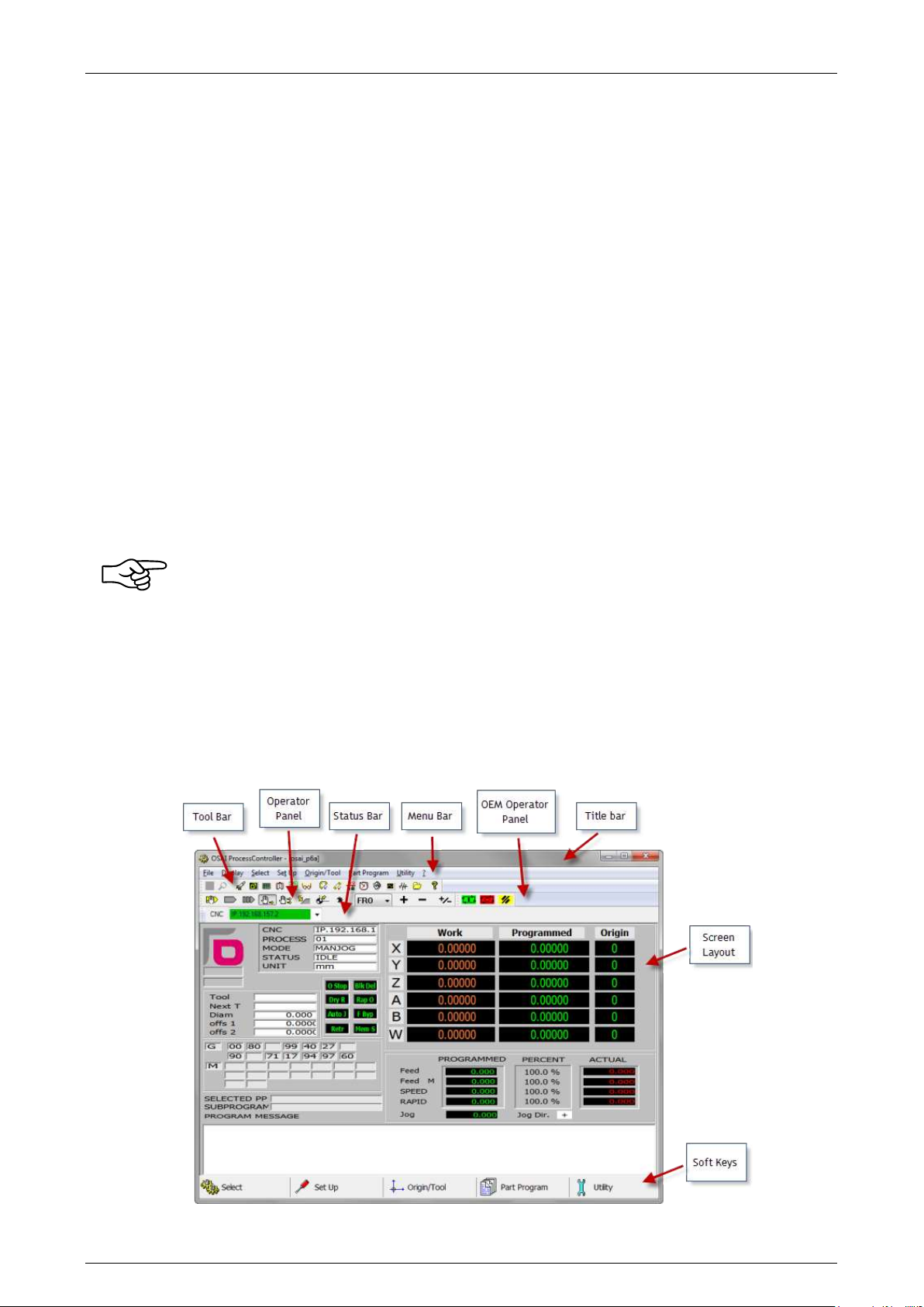
The picture below identifies the main part of the ProcessController screen
45004602H 22
Page 23
Prima Electro S.p.A. OPENcontrol – End User Manual
3.4.1 Title bar
Shows the name of the application and the name of the selected screen. The title bar can be hidden or
restored with the menu command “Display”-“Toolbar”.
3.4.2 Menu bar
Contains the main menu items, each item includes a set of commands displayed in a drop-down menu.
The items in the drop-down menu typically open a panel for the introduction of commands and
parameters. The most frequently used menu items are repeated in the Softkey task bar. The menu bar
can be hidden with the menu command "Display" - "Menu". To re-display the menu, press the keys "Ctrl"
and "P" on the keyboard.
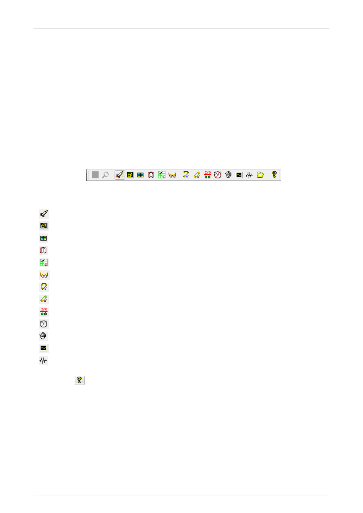
3.4.3 Tool bar
Contains buttons to activate all the WinNBI applications:
The buttons enable the other WinNBI applications:
BootController
MachinePlot
TableEditor
SystemHistory
Digicad
PathView
ODM
Tool Calibration.
I/O config
TimeMonitor
Security
O-Scope
O-Scope.NET
The button opens a panel that displays information referred to the software version of the
ProcessController.
45004602H 23
Page 24
Prima Electro S.p.A. OPENcontrol – End User Manual
Code
Mode
Use
MDI
Opens the MDI (Manual Data Input) data entry to allow
keyboard entry of a program block.
AUTO
Selects the continuous execution mode of the selected part
program.
BLK/BLK
Selects the block to block execution mode for the selected part
program
MANJOG
Enables continuous manual movements. Pressing the [CYCLE
START] button, starts the movement of the selected axis, The
movement stops when the Cycle Star button is released. For
details, see Ch. 5 “Axes jogging and Stop functions”.
JOG INCR
Enables incremental manual movements. Pressing the [CYCLE
START] button, the incremental movement defined for the
selected axis starts. For details, see Ch. 5 “Axes jogging and
Stop functions”.
PROFILE
Enables the return to the profile after a manual movement. For
details, see Ch. 5 “Axes jogging and Stop functions”.
HOME
Enables axes homing
HANDWHEEL
Enables management of the handwheel
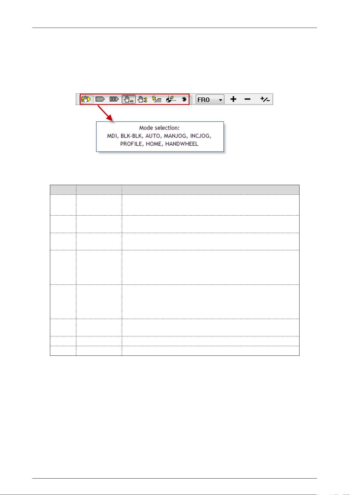
3.4.4 Operator Panel bar
It is a bar with buttons to select the CNC operating mode and the feedrate and spindle override values.
Mode selection
The CNC has different modes of operation, to move the axes in both manual and programmed mode. The
operator panel allows the mode selection.
All the buttons select only the desired mode, without starting any machine movement. The machine
movements must be confirmed with a dedicated command, usually the Cycle Start button.
The selected mode is displayed on the screen in the “CNC status” area. See the description of the main
video screen in following pages.
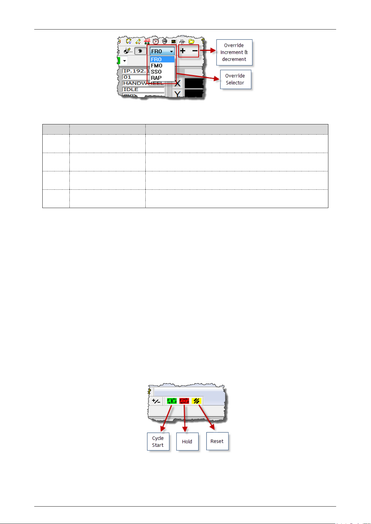
Selector and switches to change the override values
In the toolbar, are the override selector (percentage increase/decrease) and the buttons “+” and “-“ to
change the value of the selected override.
Using the override selector it is possible to select the type of override that will be changed with the “+”
and “-“ buttons.
45004602H 24
Page 25
Prima Electro S.p.A. OPENcontrol – End User Manual
Code
Definition
Use
FRO
Feed Rate Override
Percentage change in the cutting feed defined by Part
Program with the "F" function.
FMO
Feed Manual Override
Percentage change in the feed defined in the AMP
configuration for manual operations.
SSO
Spindle Speed Override
Percentage change in the rotational feed of the spindle
programmed by Part Program with the "S" function.
RAP
RAPid override
Percentage change in the feed defined in the AMP
configuration for rapid movements.
The codes listed in the selector override values have following meanings.
The current values of the override are displayed on the screen in the area “Feed and Overrides”. See
description of the main video screen in the following pages.
Button “+”
Adjusts the feedrate, spindle speed or the rapid feed, depending on the function selected by the
override selector. Each time the button is pressed, the percentage of the selected feed/speed is
increased by a pre-set amount.
Button “-”
Adjusts the feedrate, spindle speed or the rapid feed, depending on the function selected by the
override selector. Each time the button is pressed, the percentage of the selected feed/speed is
decreased by a pre-set amount.
3.4.5 OEM Operator Panel
It is a password-protected button bar, for starting and stopping the movement. This bar is provided for
the OEM only to allow initial machine tests which do not involve movement of the axes. The bar contains
the Cycle Start, Hold and Reset commands.
45004602H 25
Page 26

Prima Electro S.p.A. OPENcontrol – End User Manual
File name
Screen description
osai_p6a.qv
Screen to manage program execution.
Displays a maximum of 6 process axes.
osai_p9a.qv
Screen to manage the program execution
Displays a maximum of 9 process axes.
osai_a5a.qv
Screen to manage the programs in automatic. Displays a
maximum of 5 process axes.
osai_a9a.qv
Screen to manage the programs in automatic.
Displays a maximum of 9 process axes.
osai_m9a.qv
Screen to manage up to 9 axes in manual mode
osai_aux.qv
Screen to manage the auxiliary axes of the machine logic
3.4.6 Screen layouts
These may be the standard screen layouts provided by Prima Electro or one of the customised screens
defined by the OEM.
Remember that the video screen structure can be changed by the OEM and therefore the screens
displayed to the end user may be different to those described in this manual. Usually, the screens
contain data of the process under control.
The ProcessController can automatically resize all the objects and the texts to adapt to the main
window dimensions and therefore to the dimensions of the monitor used.
The table below lists the standard screens provided by Prima Electro with the numerical control software
and the WinNBI.
The default configuration of the ProcessController is set to display the sequence of screens osai_p6a,
osai_a5a, osai_m9a and osai_aux.
The selection of a screen with the sequence above, is managed by the F4 key or via the menu command
“Select – Next page”. The standard screen of the ProcessController dedicated to process control is
described below. Remember that the screen setting depends on the OEM’s choices and may vary
significantly from those described in this manual.
This manual describes the “osai_p6a” screen containing all the display elements related to a
process.
The other screens show the same data as in the “osai_p6a” screen, but rearranged to facilitate the use
of the machine in manual or automatic mode.
3.4.7 SoftKey bar
Like the main menu items, each softkey selects a group of commands that are displayed in a drop down
menu. The items in the drop-down menu usually open a panel for the introduction of parameters and
commands. All the softkeys are repeated in the main menu.
The softkey bar can be hidden from and restored to view with the menu command “Display” –
“Softkey”. The softkeys can be activated, by using a mouse, touch screen or with the function keys F5
to F9.
45004602H 26
Page 27
Prima Electro S.p.A. OPENcontrol – End User Manual
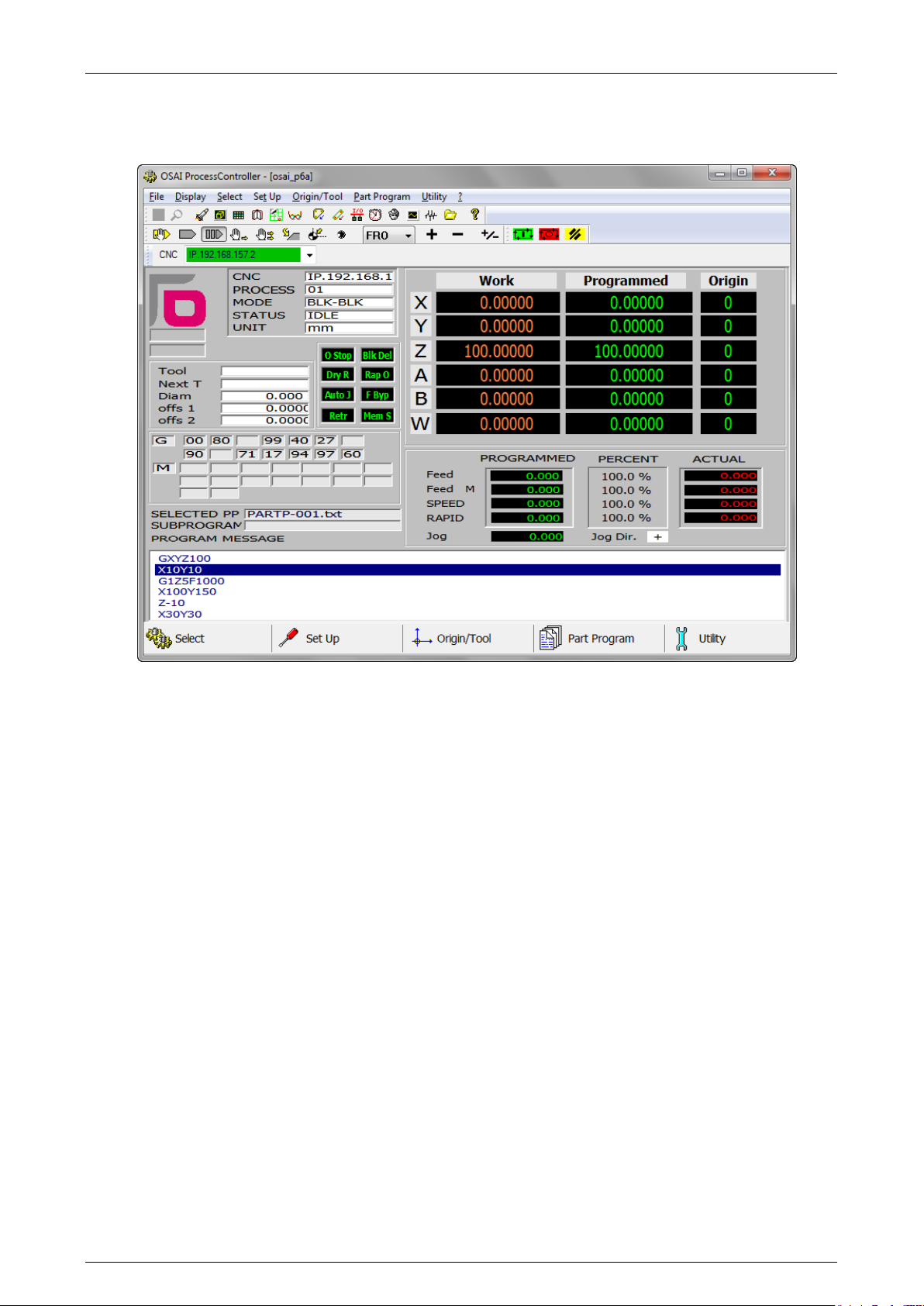
3.4.8 Main video screen osai_p6a.qv
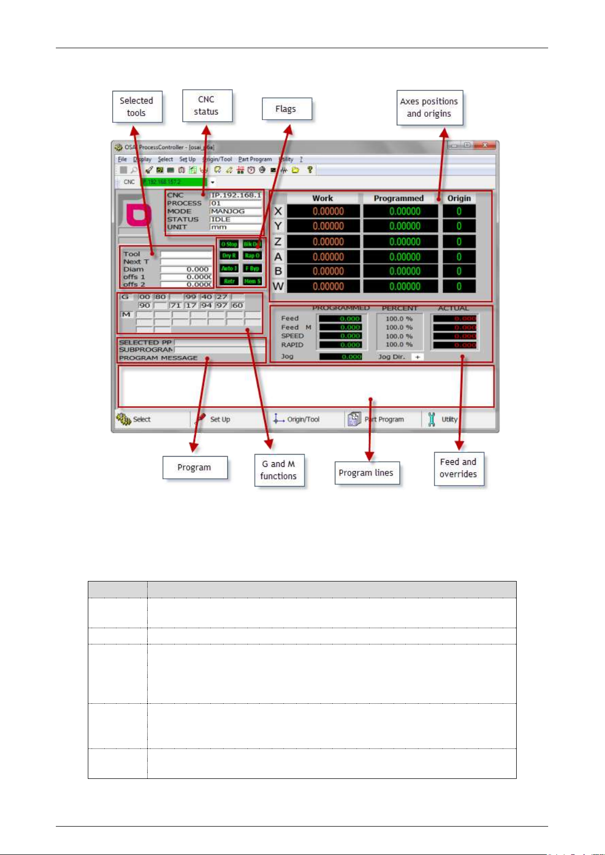
This manual describes the “osai_p6a” screen that contains all the display elements related to a process.
“osai_p6a” is a complete screen for the display of up to 6 process axes, that can be used for machining
in all modes (automatic and manual).
The screen may be overlaid by other windows with additional information, these windows may appear
automatically or on demand or according to user commands from menus and softkeys.
45004602H 27
Page 28
Prima Electro S.p.A. OPENcontrol – End User Manual
Field
Description
CNC
Name of the Numerical Control connected on the network. The data
displayed on the screen are referred to this NC.
PROCESS
Displays the number of the process selected and being controlled.
MODE
Displays the current operating mode, which can be either Automatic or
Manual. The following belong to the modes:
Automatic: AUTO, BLK/BLK, MDI
Manual: JOG CONT, HOME, JOG INCR, JOG RETURN, HANDWHEEL
STATUS
Displays the status of the currently selected process. Some are valid for both
Automatic and Manual modes, while others are possible in only one mode.
The possible states are: INPUT, ERROR, EMERG.
UNIT
Indicates the current unit of measurement for the selected process. It can be
mm (millimetres) or inches
The osai_p6a screen has been divided into several functional areas, as shown in the following figure.
CNC Status Area 3.5
The Status Area contains information referring to the operating status of the numerical control:
45004602H 28
Page 29

Prima Electro S.p.A. OPENcontrol – End User Manual
STATUS
AUTO
MAN
MEANING
IDLE
The process is stopped waiting for a command.
IN CYCLE
The process is executing a part program or a command
entered from the keyboard in MDI mode.
RUN
The process is performing a manual movement.
CYCLE STOP
The execution of a part program or a command provided
in MDI was stopped and the process is in a wait state.
HOLD
The execution of a manual movement was interrupted
with CYCLE STOP button and the process is in a wait
state.
RUNH
The process has been stopped during the execution of a
part program with CYCLE STOP. Switching the process in
MANUAL, the status changes from STOP to HOLD CYCLE.
If one or more axes are manually moved, during these
movements the message becomes RUNH and buttons
CYCLE START and CYCLE STOP are both turned on.
RUNH informs the user that there is an on-going
movement.
HRUN
With the process in the HOLD or CYCLE STOP state and
CYCLE STOP is pressed, the status switches to HRUN
which means that the process is ready to continue the
interrupted machining. The CYCLE STOP button will
turn off and the process waits for CYCLE START to be
pressed.
RESET
Indicates that the process is still managing the reset
command following pressing of the RESET button.
WAIT
The process is waiting to be synchronized with another
process.
INPUT
Indicates that the process is waiting for a data input
from the keyboard (a data entry window is on the
screen).
ERROR
Indicates that the process has detected an error during
operation. The error can stop the process or be managed
by the part program.
EMERG
The system detected an anomaly, and operator
intervention is required. The type of fault is indicated
on the screen with an explanatory message explained in
the Appendix A ("Emergency Messages").
Each of the aforementioned states is briefly described in the table. More detailed information will be
provided in the explanations of operator actions in which they are involved.
45004602H 29
Page 30
Prima Electro S.p.A. OPENcontrol – End User Manual
Flag
Description
OSTOP
Optional Stop (Ready to stop when M01 occurs in the program)
BLK DEL
Block Delete (blocks preceded by / are omitted
DRY R
Dry Run Program executed without axis movement
RAP O
Rapid Override
Auto J
F Byp
Feed rate Bypass
Retr
Retrace
MemS
Search Memory
Mode
Sub-mode
Status
Flag
AUTO
BLK/BLK
MDI
IDLE
RUN
HOLD
HRUN
RUNH
WAIT
INPUT
EMERG
ERROR
RESET
OPTIONAL STOP
BLOCK DELETE
FEED BYPASS
RETRACE
RCM O
N
MANUAL
HOME
JOG INCR
JOG RETURN
HANDWHEEL
IDLE
RUN
HOLD
HRUN
RUNH
EMERG
ERROR
RESET
RETRACE
JOG+
JOGRCM ON
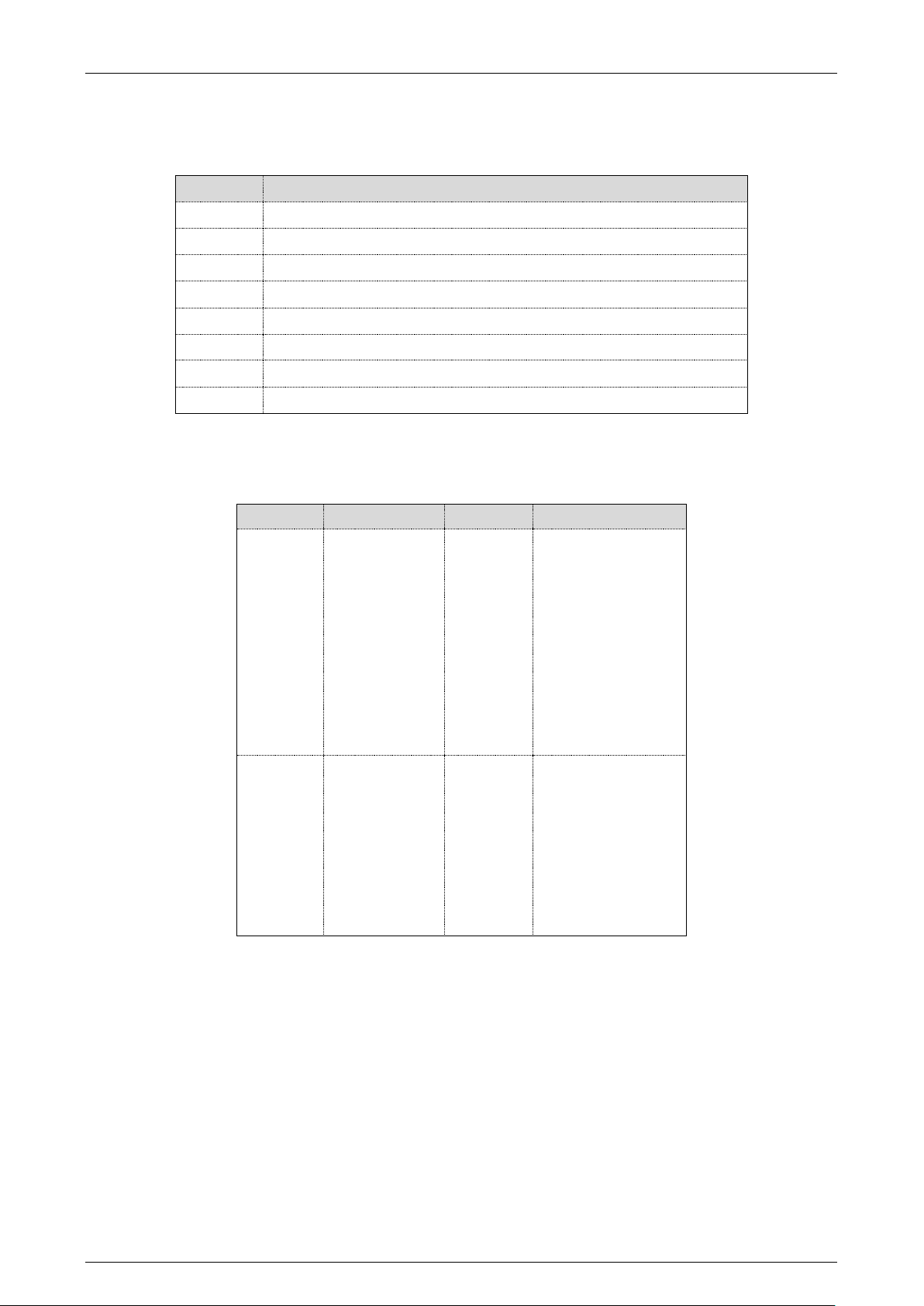
Flags Area 3.6
The active options referred to the current mode, are displayed in reverse in the flag area
The table below lists (for Automatic and Manual mode) the sub-modes available, the possible process
status and the flags used.
45004602H 30
Page 31
Prima Electro S.p.A. OPENcontrol – End User Manual
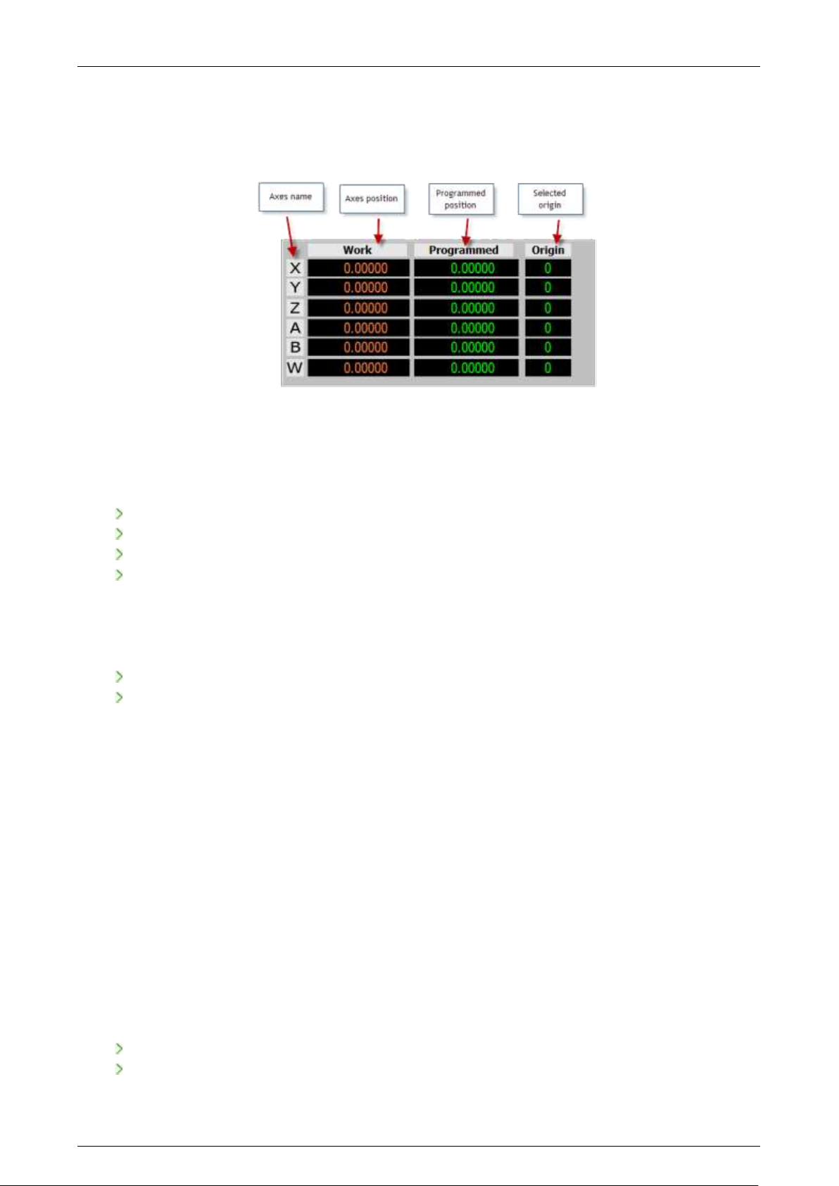
3.6.1 Axes positions and origin area
This area of the main screen displays the position data the origins of the process axes. The figure below
indicates the elements contained in the area. The data are arranged as a matrix where each line belongs
to the axis whose name is shown in the first column.
Axes name
The axis name is a letter identifying an axis within a process. Unlike a physical axis identifier, that is a
unique number in the system, the axis name can be repeated in another process.
The axis name in reverse indicates the axis selected for manual movements. The selection can be made
in different ways:
Clicking with the mouse on the axis name
Sequentially, via the command menu or softkey “Select” – “Next Axis”
By the Cursor Up/Down Keys
Sequentially, by pressing “Ctrl” and “A” simultaneously.
Axes position
The label of this column indicates the type of positions displayed in the fields below. The content of this
field changes according to the selection made by:
the softkey or menu command “Select” – “Positions”
Sequentially, from the keyboard by pressing the keys “Ctrl” and “B”.
The position types that can be displayed for the process axes are:
Work position calculated with respect to the current origin
Machine actual position calculated with respect to the current origin
To go distance to go (difference between current and commanded position)
Error following error, i.e. the difference between the positions Work and Machine.
Absolute absolute position referred to the home position ignoring offsets & origins
The positions of the axes are displayed with 10 digits in the formats 7.3, 6.4 or 5.5 (where the first digit
represents the integers, the second the decimals) according to what has been configured in AMP for
each axis.
Programmed position
This is the last position programmed from part program or MDI command. It is 10-digits long, displayed in
the same format as the “Axis position” fields.
Selected Origin
Number and type of the origin selected for the axis. In this field are also displayed characters:
- “T” for temporary origins
- “I” for incremental origins
If only the origin is displayed, then the origin is absolute, not temporary or incremental.
45004602H 31
Page 32
Prima Electro S.p.A. OPENcontrol – End User Manual
3.6.2 Feed and overrides Area
This area contains the information related to the machining speed and movement of the machine. The
values in this area are expressed in current units of the process (mm / inches), which is also displayed on
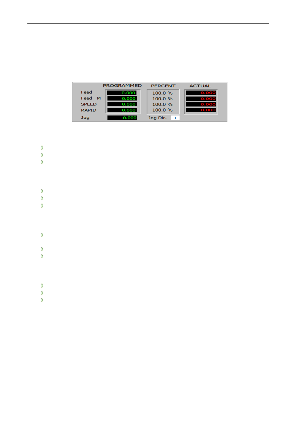
the screen.
The information in this area is arranged in a matrix where the lines refer to the type of speed indicated
by the labels in the first column.
Feed line
Contains the information referred to the machining feedrate. From left to right, the data indicates:
The feedrate set by program
the selected feedrate override
actual feedrate (programmed * feed override)
Feed M line
Contains the information referred to the manual feedrate. From left to right, the data indicates:
the configured feed for manual movements
the selected manual feedrate override
the actual manual feedrate (configured * override)
SPEED line
Contains the information referred to the spindle speed. From left to right, the data indicates:
the programmed revolutions. If the Constant Surface Speed (CSS) is active, the field indicates
the calculated speed based on the programmed one which varies as the work diameter changes
the selected speed override
the override speed of the spindle (rpm or CSS) * override.
RAPID line
Contains the information referred to the axes rapid feedrate. From left to right, the data indicates:
rapid feedrate configured in AMP
the selected rapid feedrate override
the actual rapid rate (configured * override)
Jog field
It’s the incremental distance set for the execution of manual movements (incremental Jog).
Jog Dir. field
Indicates the direction of movement set for manual movements (Jog and incremental Jog).
45004602H 32
Page 33
Prima Electro S.p.A. OPENcontrol – End User Manual
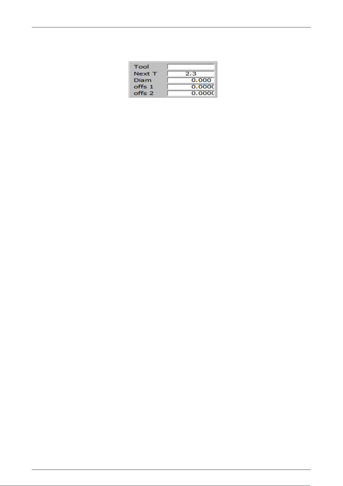
3.6.3 Selected Tools Area
The area is dedicated to the display of the programmed tools.
Tool
Number of the tool mounted on the spindle and its active offset. The field contains 2 groups of digits
divided by a point. The group on the left of the point represents the tool number, the one on the right
the offset.
Next T
Number of the next tool and its associated offset that will be mounted in the spindle. This is the tool
already set by the program, but not yet mounted in the spindle.
The field contains 2 groups of digits divided by a point. The group on the left of the point represents the
tool number, the one on the right the offset.
Diam
Diameter of the tool mounted in the spindle.
Offs 1
Length 1 offset of the tool. The machine axis to which the tool compensation refers to in this field is
configured in AMP via the ODM application.
Offs 2
Length 2 offset of the tool. The machine axis to which the tool compensation refers to in this field is
configured in AMP via the ODM application.
Offs 3
Length 3 offset of the tool. The machine axis to which the tool compensation refers to in this field is
configured in AMP via the ODM application.
Offs 4
Length 4 offset of the tool. The machine axis to which the tool compensation refers to in this field is
configured in AMP via the ODM application.
Offs 5
Length 5 offset of the tool. The machine axis to which the tool compensation refers to in this field is
configured in AMP via the ODM application.
45004602H 33
Page 34
Prima Electro S.p.A. OPENcontrol – End User Manual
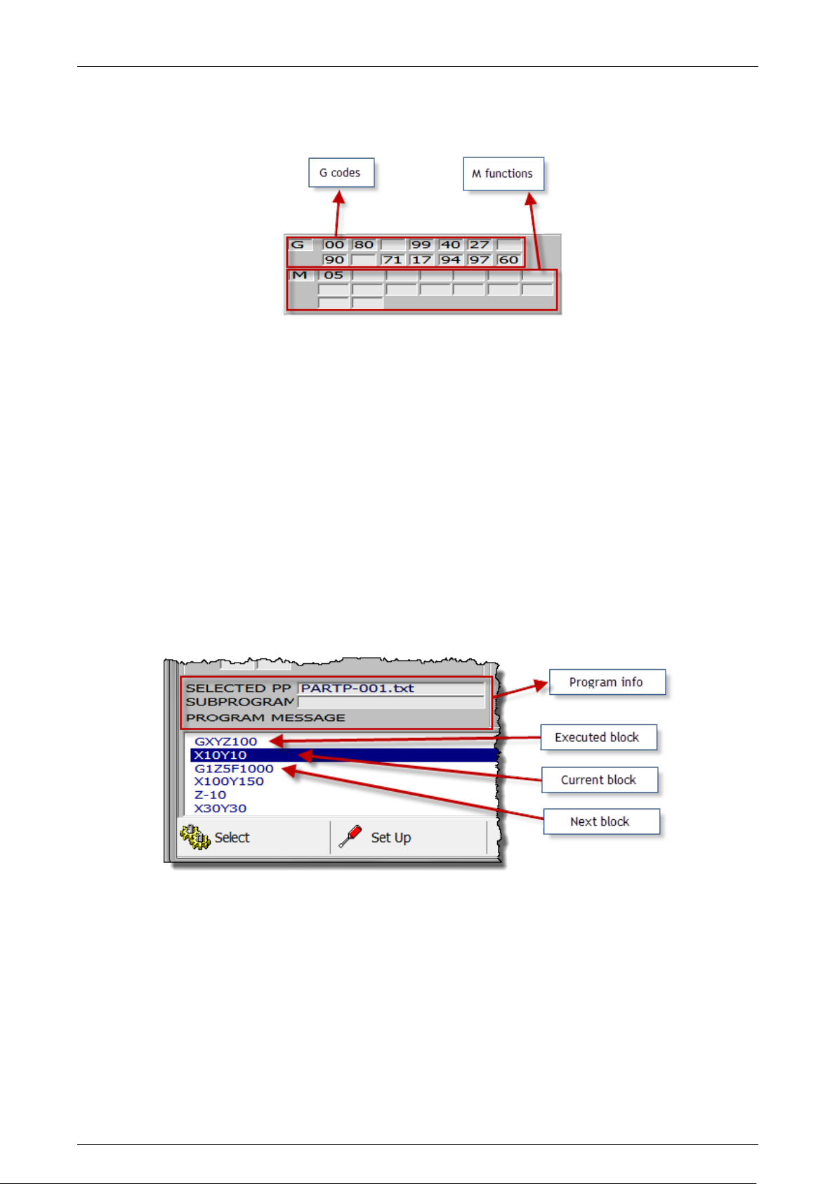
3.6.4 G and M functions Area
Area that displays the active G codes and M functions.
G codes
Active G codes. The codes are divided into display groups. Each field displays the active G code for one
of the modal groups defined in AMP.
M functions
Active M functions. Usually each field displays an M code for every modal group configured in AMP.
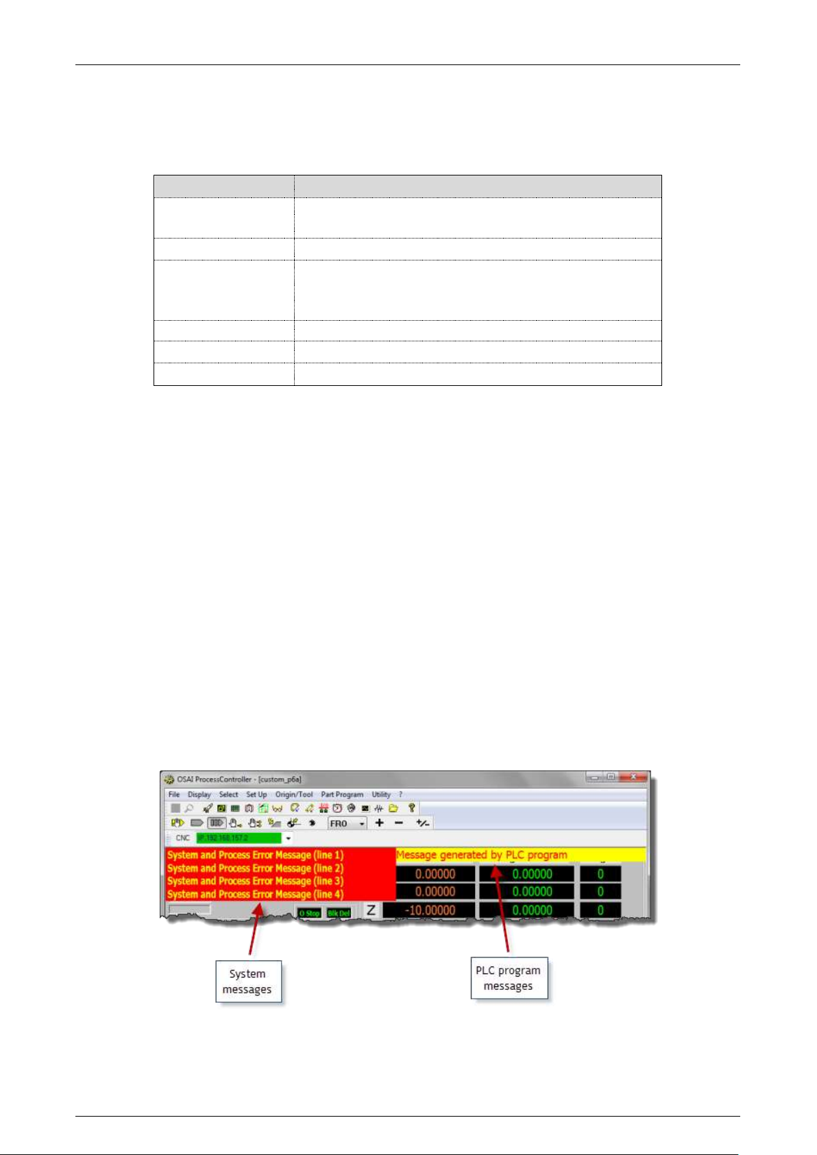
3.6.5 Part program data area
This is the area dedicated to the display of the lines of the part program being executed. The area is
read-only, at this point you cannot edit the program.
In order you will find, the block already executed, the block being in execution highlighted in reverse
and the blocks still to be executed. The part program lines automatically scroll upward as they are
executed by the CNC. The figure below shows an example of the lines of a program in execution:
SELECTED PP
It’s the name of the main program selected.
SUBPROGRAM
Contains the name of the sub-program selected. The name is displayed only when the sub-program is
enabled. A sub-program can call another sub-program. The sub-program displayed is always the one with
the lower nesting level, i.e. the last called and still in execution.
PROGRAM MESSAGE
Messages defined in the part program with the DIS, command.
45004602H 34
Page 35
Prima Electro S.p.A. OPENcontrol – End User Manual
Flag
Description
F4
Sequential selection of the screens to be displayed from
a list of active screens
F5, F6, F7, F8 F9
Activation of the corresponding softkey
Ctrl + A,
key ↑,
key ↓
Sequential selection of the axis to be moved in manual
mode
Ctrl + B
Sequential selection of the axes position type
Ctrl + P
Sequential selection of the selected process
Ctrl + T
Sequential selection of the selected target (CNC)
Keyboard Commands 3.7
The following tables summarizes the keyboard commands used as “accelerators” to enable the
commands associated with the menu items.
3.7.1 Additional information windows
In addition to the information normally provided by the main video screen, additional information in
specific windows can be displayed as required. These windows overlay the current screen and appear
only upon request or when the system has to inform the user (for instance, via a message).
The possible additional windows are:
MDI Command Panel
It is the panel for the MDI commands entry, i.e., for the execution of single command lines using the
same syntax as used for the part program lines. For additional details, see the paragraph “MDI Panel
Functions ”
Messages from System
Information messages from the system or process displayed in four lines (see figure)
Messages from PLC Program
Signalling messages generated by the machine logic program. (see figure)
45004602H 35
Page 36
Prima Electro S.p.A. OPENcontrol – End User Manual
Panels for Command and data input 3.8
The ProcessController has several data entry windows used to enter commands, working parameters,
configuration, parameter setting for the movements in manual and automatic. Usually the data entries
are enabled by the commands associated with the softkeys described in the previous paragraphs.
This chapter explains the function of all the process Controller data entries.
3.8.1 General rules on the input windows
With the standard screens, the data can be entered in the system only by using specific windows defined
as “input windows” or “data-entry”. usually, the data-entries appear in the current screen after
enabling an item in the main menu or with the softkey.
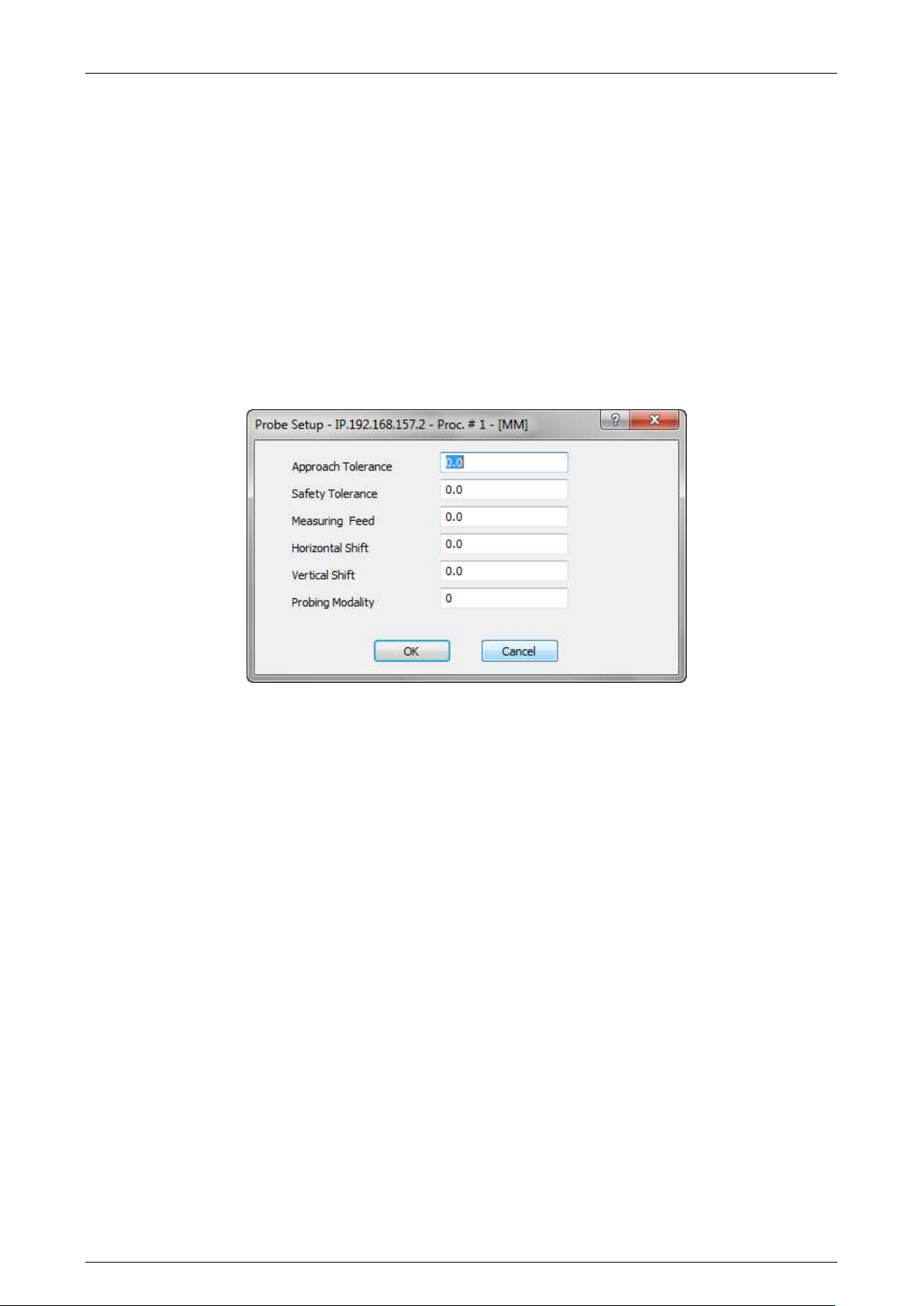
For proper handling of input data it is necessary to apply some rules that are common to all input
windows in the system. Below is an example of input window.
Each input window has fields that can contain parameters, file name, device names and so on. The
values entered must comply with the type and the format of the field.
In the case of fields with parameters depending on the unit of measurement (mm / inches), the
numerical values associated with them will be displayed in the unit of measure defined for the process
with the default AMP configuration. The information is displayed in the title of the window.
The cursor is positioned on the selected input field. When the data-entry is opened the first input field is
selected. With the operator panel touch-pad or with the touch-screen function, it is possible to select
the desired field.
45004602H 36
Page 37
Prima Electro S.p.A. OPENcontrol – End User Manual
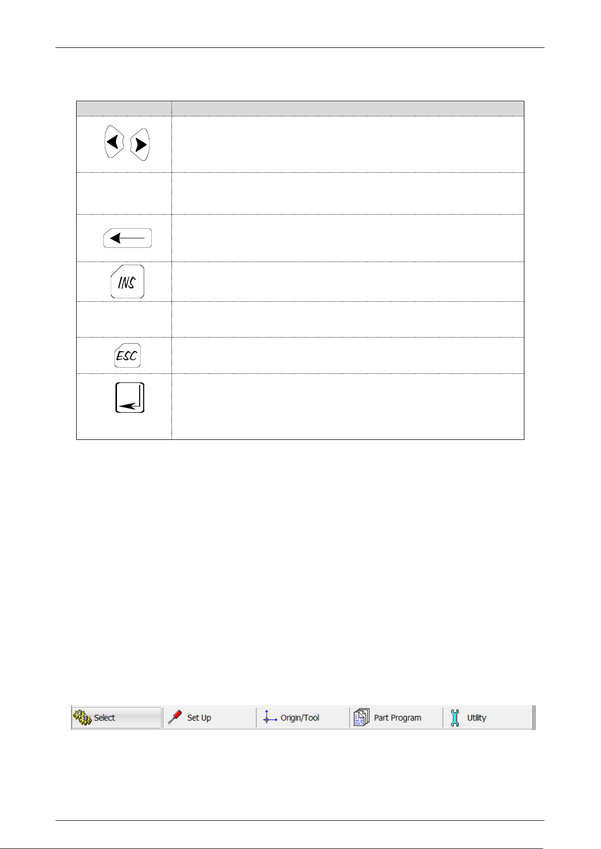
KEY
FUNCTION
Moves the cursor to the right or to the left inside the field.
CANC or DEL
Deletes the character to the right of the cursor.
Deletes the character to the left of the cursor.
Toggles between overwrite and insert modes..
TAB
Moves the cursor on the following field
Aborts the current data entry window.
Confirms the current data entry window.
The characters inserted via the keyboard are displayed on the screen as the cursor is moved. Data entry
can be managed using the following keys:
The input window can be exited at any time. If the data is not confirmed, the values inserted are not
applied.
To exit the input window, cancelling the data entered, press "Cancel".
To exit the input window and validating the data entered, press "OK".
3.8.2 The ProcessController soft-keys
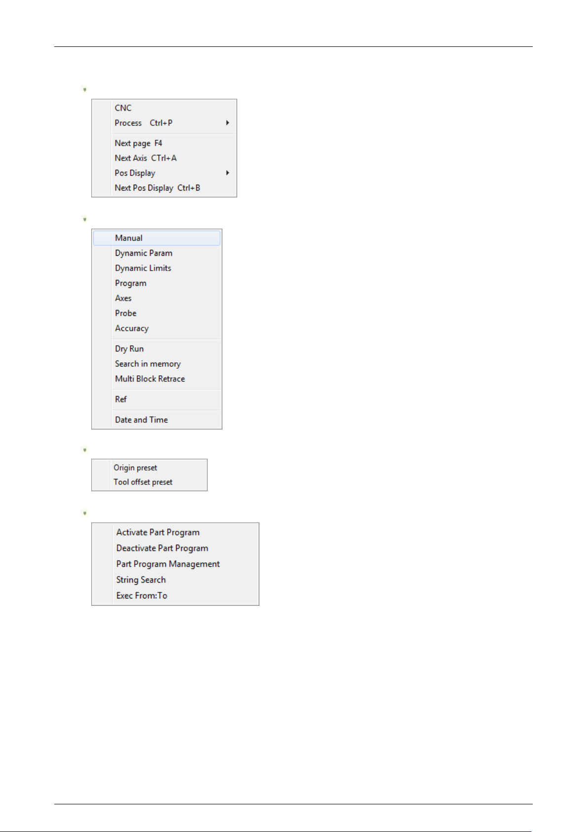
The ProcessController interface is controlled through the mouse or keyboard. To simplify access to all
the CNC commands through the keyboard, some special keys have been added at the bottom of the
application window, the soft-keys. The soft-keys are activated by pressing the OSAI Operator Panel F5,
F6, F7, F8, and F9 function keys, the Touch-pad mouse or the Touch-screen function
The soft-key activation opens a drop-down menu. To select the desired menu item from the keyboard
use the arrow keys (cursor up, cursor down).
All the commands available with the soft-keys are also present in the main menu.
The ProcessController soft-keys are the following:
45004602H 37
Page 38
Prima Electro S.p.A. OPENcontrol – End User Manual
The drop-down menus opened by the softkeys are shown below:
Select
Set Up
Origin/Tool
PartProgram
45004602H 38
Page 39
Prima Electro S.p.A. OPENcontrol – End User Manual
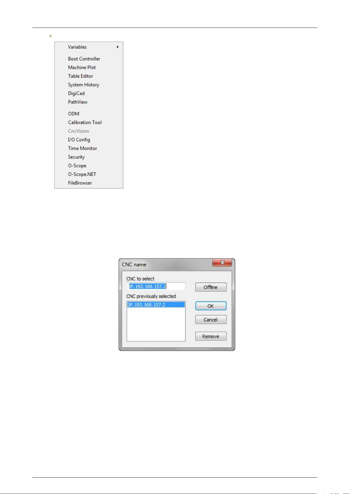
Utility
The panels opened by the drop-down menu items are explained In the following pages.
“Select” – “CNC”
This command changes depending on the configuration of the type of connection (single or multiple).
The configuration is set using the configuration panel reserved for MTB use.
If the ProcessController has been configured for a single connection, the selection panel is as follows:
Permits selection of the CNC to be connected to the network.
When the WinNBI is connected to the CNC control unit, use the generic local address indicated by “IP.”
to address the local CNC. The remote CNCs are addressed by the prefix “IP.” followed by the TCP/IP
address of the control unit (as shown in the picture). By using the Offline button or writing NULL instead
of the CNC name it is possible to disconnect the CNC. This mode can be used by an offline PC in order to
use the Layout Builder only.
When the offline mode is active the ProcessController displays an empty screen layout.
In this condition ProcessController doesn’t try to connect to the selected CNC.
The "Remove" button is used to remove an unused name from the history of the CNC previously
connected. The key removes the selected name from the “CNC previously selected” list.
45004602H 39
Page 40
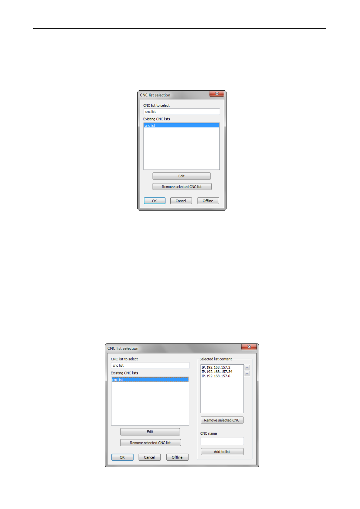
Prima Electro S.p.A. OPENcontrol – End User Manual
3.8.3 Multiple connection, CNC selection
Multiple connection permits a list of CNCs to be specified to be connected contemporaneously.
It is used and useful only when the screen layout has been designed to show the data of more than one
CNC at the same time.
If the ProcessController has been configured for multiple connections, the selection panel is as follows:
This panel is used to set the name of the selected list. The list contains the names of all the numerical
controls to be connected simultaneously. To select the offline mode write “NULL” in the field “CNC list
to select”.
The "Remove list" button may be used to delete an unused list (the button removes the selected name
from the list).
To define the content of the list, press Edit.
The list selected is the one shown in the "CNC list to be selected" box.
If the list does not exist yet, a new empty list is created.
The Edit button opens (and closes upon being clicked again) the dialog window dedicated to the
composition of the list. The dialog window can be edited as shown in the figure below:
45004602H 40
Page 41
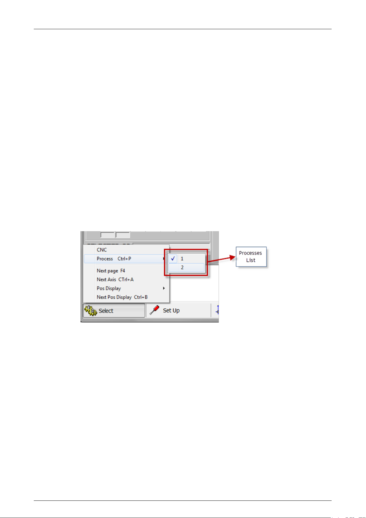
Prima Electro S.p.A. OPENcontrol – End User Manual
By means of the "Remove selected CNC" button you can remove the selected CNC from the list of CNC’s
to be connected. The "Add to list " button adds to the list the network name of the CNC specified in the
"CNC name" field. The name is added to the list only if it not already present and if the list contains
fewer than eight names.
The Up and Down arrow buttons next to the list of CNCs allows the position of the selected CNC name to
be changed.
CAUTION:
The order of the names in the list is very important, since the information displayed in ProcessController
screens depends on it. If a screen box has been configured to show a value of CNC # 1, the
ProcessController will get the value from the first CNC in the list; if a box has been configured for CNC #
2, the value will be taken from the second CNC, and so on.
When a multiple selection is active, the ProcessController enables selection of one of the CNCs from the
status bar, or sequentially using the keyboard command CTRL+T. The selection from the status bar is
made by selecting one of the items in the list by means of the "Arrow down" button next to the "CNC"
field.
“Select – Process”
Allows selection of a process from those configured in AMP.
The existing processes are listed in a drop-down menu.
If there is only one process, the command is disabled.
If the screen is valid for the new process selected, the screen does not change, instead it will display the
first screen of the sequence assigned to the process.
The command can also be sent from the keyboard by simultaneously pressing the keys “CTRL” and “P”.
“Select” – “Next page”
Selects, sequentially, the screen following the sequence of the screens in use.
The command can be sent from the keyboard (key “F4”).
“Select” – “Next axis”
Selects, sequentially, the axis for manual movements.
the command can also be sent from the keyboard by simultaneously pressing the “Ctrl” and “A”.
“Select” – “Pos Display”
Allows selection of the type of position display for the axes configured in the process.
45004602H 41
Page 42
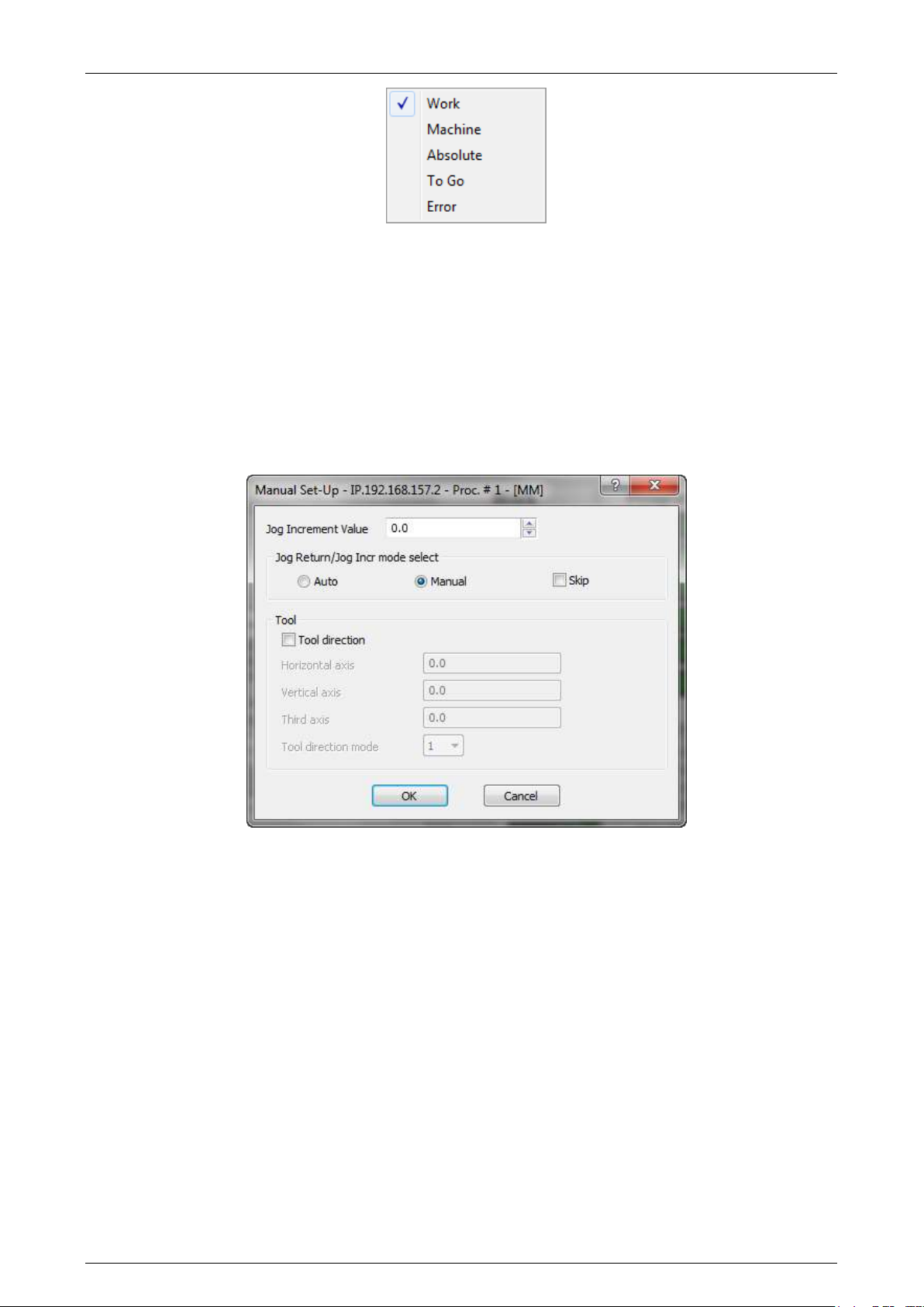
Prima Electro S.p.A. OPENcontrol – End User Manual
“Select” – “Next Pos Display”
Selects sequently the type of position display for the axes in the process. For each activation of the
command the position type display can be selected in the order Work, Machine, Absolute, To Go, Error.
The same command can be enabled from the keyboard by simultaneously pressing “Ctrl” and “B”.
“Set Up” - “Manual”
Opens a data entry window that allows the length of the axis movement to move with incremental
manual movments and the type of return after a manual movement. It also enables the tool extraction
procedure for some particular cases (see Chapter 6, " Manual Axes Movements and Stop Functions ").
Jog Value
Insert the incremental distance for incremental manual movement. The value inserted is displayed in the
JOG field of the main video screen.
Jog Return/Jog Incr mode Selection
Specifies the JOG RETURN and the JOG INCR modes, that can be automatic or manual (See Chapter 4)
Skip
Specifies whether to return to the profile from HOLD, or to position along a straight line to the end point
of the block in which the movement was suspended in HOLD. To skip a return on the profile, tick the
Skip field.
For the fields related to the “Tool Direction”, refer to Ch. 5 “Axes jogging and Stop functions”.
45004602H 42
Page 43
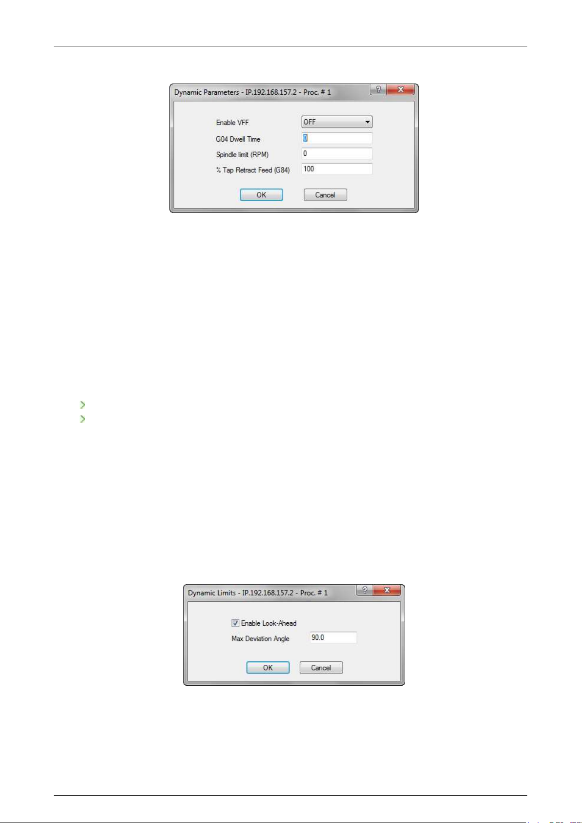
Prima Electro S.p.A. OPENcontrol – End User Manual
“Set Up” - “Dynamic Param”
Enables VFF
Enables/disables the VFF algorithm (velocity feed forvard) of the servo axes.
When the algorithm is enabled, the following error will be reduced to a value close to zero, consistent
with the gain of the servo configured in AMP, to minimize the shape error on the profile.
When the algorithm VFF is disabled, the axes are controlled only with the following error.
The value of the following error is displayed in the video area of the axis positions when selecting the
“ERROR” display mode.
Dwell time G04
Defines the dwell time at the block end (G04). This time is used with G04 and in the following blocks of
fixed cycles:
In G94 the dwell time is in seconds.
in G95 the dwell time is in number of revolutions.
For detailed information on this parameter, see the Programming Manual.
SPEED limit (RPM)
Defines the maximum spindle speed.
It is used in Constant Surface Speed (CSS), ie when the spindle feed depends on the master axis position.
Return feed % (G84)
Tapping return feed. It defines the percentage change in the feed rate applied during the return phase
of the tapping cycle. The range of values is 0-125%. The default value is 100%.
“Set Up” – “Dynamic Limits”
Enables Look-Ahead
Enables the automatic deceleration on the angles when executing a part program. If disabled, all the
DLA instructions of the current part program will be ignored.
45004602H 43
Page 44
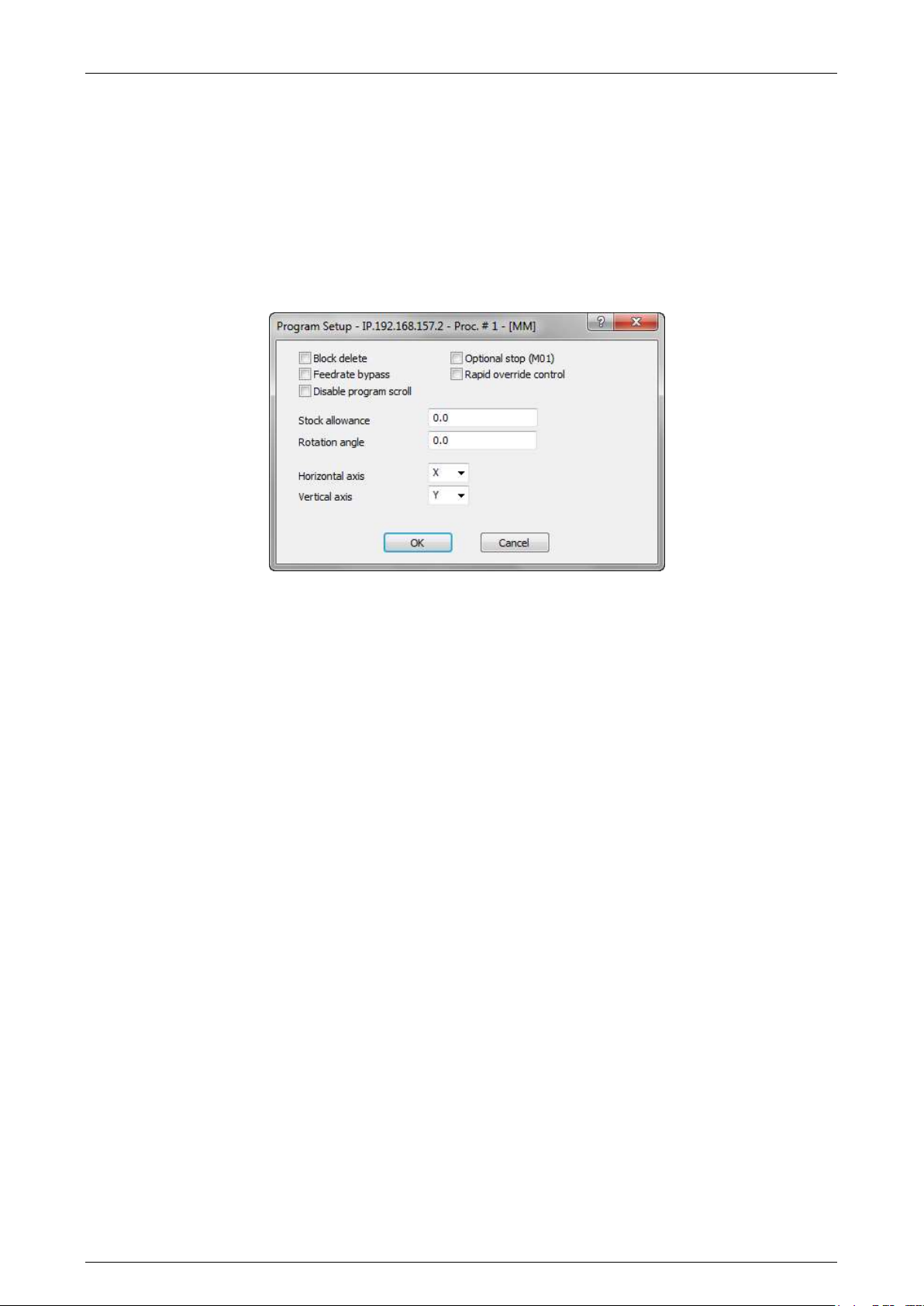
Prima Electro S.p.A. OPENcontrol – End User Manual
Maximum Deviation Angle
MDA (Maximum Deviation Angle) is the maximum angular deviation from the axis in which G27 is active.
The selected angle is the operational limit for G27. Angular deviation greater than this angle is done by
G29 or point-by-point.
“Set Up” – “Program”
Opens a data entry that allows the configuration of some paraemters that influence the part programs
execution modes.
Block Delete
Enables the block delete feature, the block preceded by a slash "/" is NOT executed (equal to the DSB =
1 programming). At system boot, this field is set to the condition established in the AMP
characterization. System reset does not change the previous setting.
Optional Stop (M01)
Enables the optional program stop. At system boot, this field is set to the condition established in the
AMP characterization. System reset does not change the previous setting.
Feedrate Bypass
It enables forcing of the rapid speed with G1, G2 or G3 active. At system boot, this field is disabled.
System reset disables this field.
Rapid Override Control
Enables control of the rapid feed precentage with the Operator Panel. At system boot, this field is set to
the condition established in the AMP characterization. System reset does not change the previous
setting.
Disable program scroll
Disables part program scroll in the AUTO mode. If scroll is disabled, the block execution is faster. At
system boot, this field is set to the condition established in the AMP characterization. System reset does
not change the previous setting.
Stock allowance
Defines the machining allowance value added to the tool radius for the calculation of the trajectory in
“tool offset” (G41 - G42) mode. It is the same as programming the MSA variable. At system boot and
after a reset, this parameter =0.
45004602H 44
Page 45
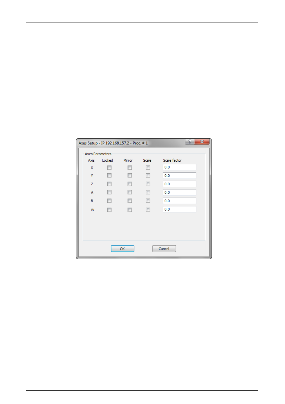
Prima Electro S.p.A. OPENcontrol – End User Manual
Rotation Angle
Defines, in degrees, the rotation of the active plane (positive value = CCW rotation). Unlike the triliteral
code by programming (ROT, angle), system reset does not reset the rotation angle. If (ROT angle) is
programmed after setting up a rotation angle with this input box, the value of the rotation of the plane
will be the sum of the rotations. Entering the angle of rotation of the plane in this window after
programming a value with the trilateral (ROT angle), the rotation of the plane will be equal to the value
entered in the data entry. In this case, the rotation preset by (ROT, angle) will be lost.
Horizontal axis – Vertical Axis
Defines the working plane. Ii is equivalent to programming G16. When the system starts-up and after a
reset, the work plane is defined by the value set in AMP (G17, G18, G19 or the alternative axis plane
(G16).
“Set Up” – “Axes Setup”
Locked
Enables the movement of the axes. When selected, the system normally execute the part program, but
the axes do not move physically. The reset does not disable this mode.
Mirror
Enable the reversal ("MIRROR") of the trajectory of the specified axis.It is equivalent to programming the
three-letter code (MIR, axis name).System reset disables this function.
Scale
Enables the scaling factor referred to the axis specified. System reset disables scaling..
Scale Factor
Defines the scale factor to be applied to the specified axis. Equivalent to programming the triliteral code
(SCF axis name, scale factor). System reset reset set the scale factor to zero.
45004602H 45
Page 46
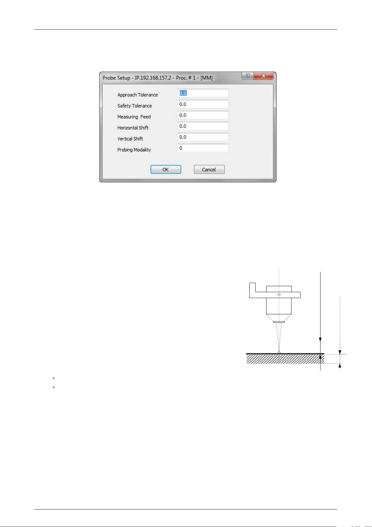
Prima Electro S.p.A. OPENcontrol – End User Manual
Safety Tolerance
Approach Tolerance
“Setup” - “Probe Set Up”
Opens an input window for the entry of the probing parameters.
Approach tolerance. Represents the distance from the probing target. The probe moves this distance in
rapid and then starts the probing cycle at the feedrate programmed in the entry Measuring Feed.
Safety Tolerance.
A value that prevents damage to the probe. If the probe does not find the target within this range, it
stops.
Measuring Feed
The feed with the probe moves towards the target.
Horizontal Shift
The value for the abscissa axis of the probe requalification in
millimetres.
Vertical Shift.
The value for the ordinate axis of the probe requalification in
millimetres.
Probing Mode
The value of the probing mode:
0 for the standard probing (return to start point)
1 for the probe to remain at the probed position
“Setup” – “Set Accuracy”
Opens a data-entry to define the parameters related to circular interpolation.
45004602H 46
Page 47
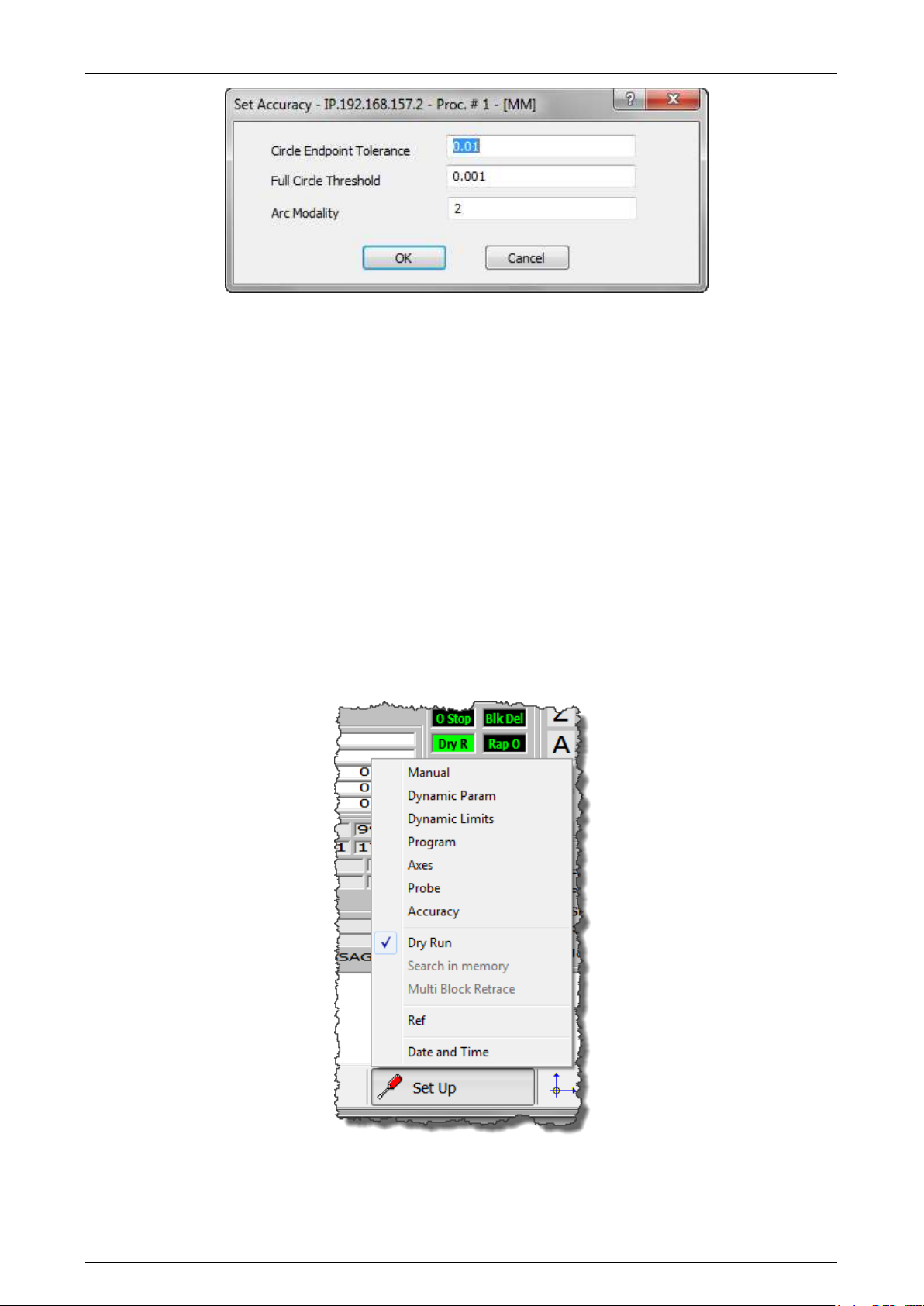
Prima Electro S.p.A. OPENcontrol – End User Manual
Circular Endpoint Tolerance (CET)
Defines the tolerance for the difference between the initial and final arc of a circle.
Full Circle Threshold (FCT)
Determines a tolerance for the distance between the first and the last point of the arc of the circle. If
the distance is less than the value of FCT, the arc is to be considered a full circle.
Arc Modality (ARM)
Determines the mode applied by the system to normalize a programmed arc with center coordinates (I,
J) and the end point, in order to make it geometrically congruent. The valid values are 0, 1, 2 and 3.
0 displaces centre within the CET tolerance (default mode)
1 displaces starting point within the CET tolerance
2 displaces centre independent of the CET tolerance
3 displaces centre beyond the CET tolerance range
“Set Up” – “Dry Run”
If Dry Run is selected it is possible to test the part program execution without any physical axis
movement or command being sent to the machine logic.
45004602H 47
Page 48
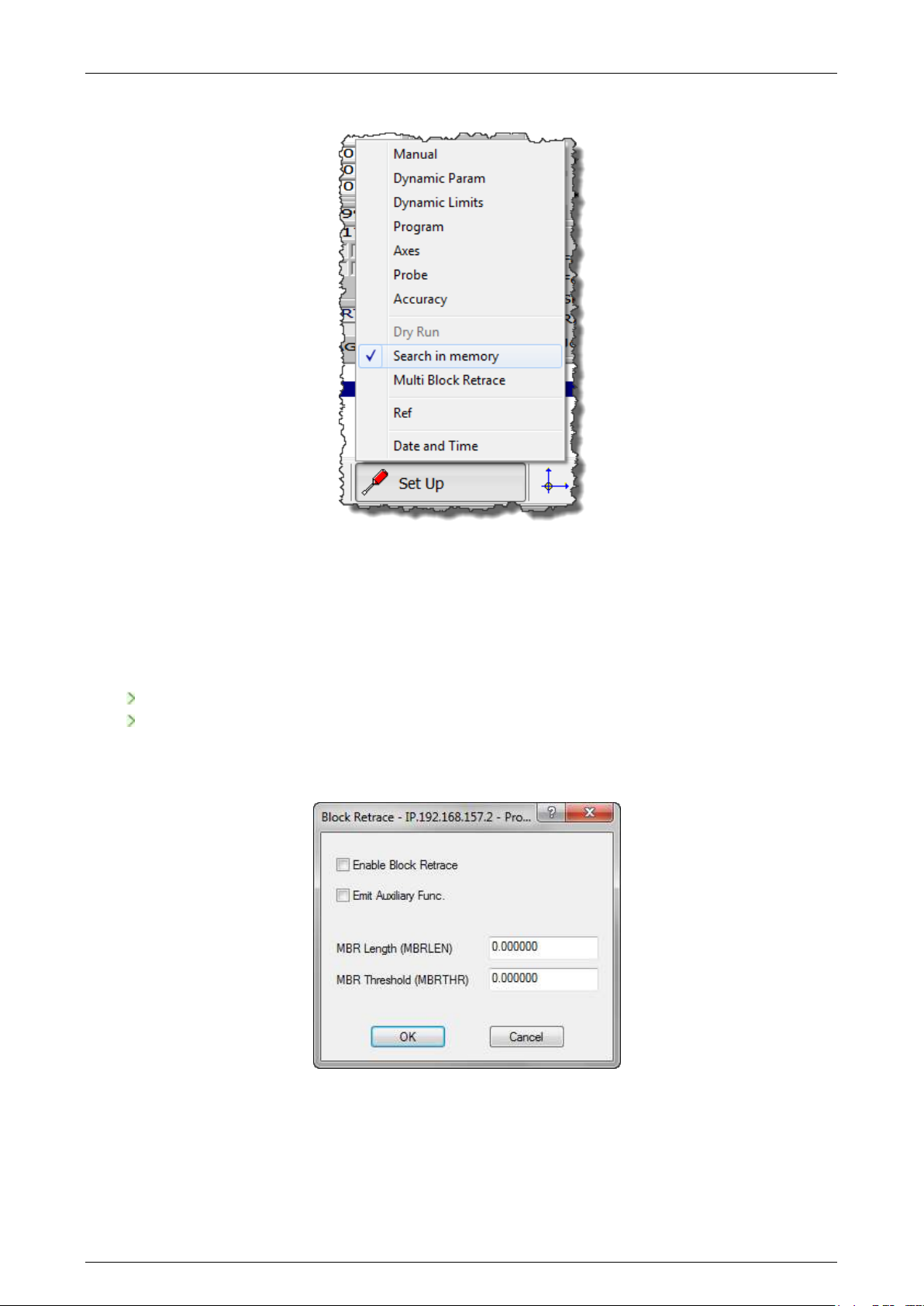
Prima Electro S.p.A. OPENcontrol – End User Manual
“Set Up” – “Search in Memory”
Search in memory: is the search for point in the program where it was interrupted and the subsequent
recovery cycle or the search for a block where processing will begin. The parameters that uniquely
identify a interrupt at run time are stored and continuously updated during the execution of the
program. Based on these parameters, the control has the ability to perform an automatic search.
The strored search can be done in two ways:
Stored search of the interruption block (following a shutdown or reset).
Stored search of to a specific block
“Set Up” – “Block Retrace”
This function allows blocks to be executed backwards with axis movements in reverse along the profile
previously executed. The number of blocks that can be executed backwards may vary from 1 to 64,
depending on the AMP configuration.
45004602H 48
Page 49
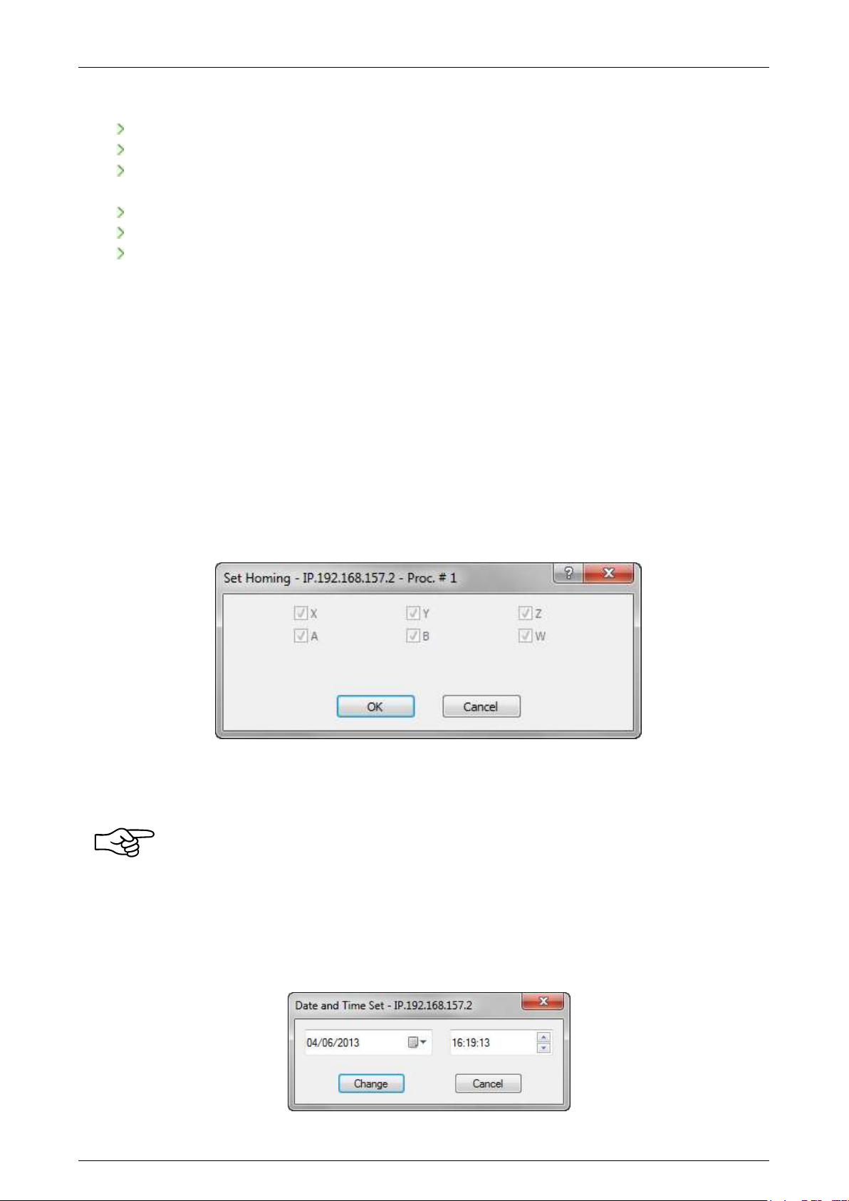
Prima Electro S.p.A. OPENcontrol – End User Manual
The sequence of the operations to execute the commands backwards is:
Stop the running program by pressing Cycle Stop.
Activate Block Retrace through the data-entry.
Press the "Cycle Start" key: the system moves the axes backwards along the path stored during
the program execution..
The movements will be executed in selected mode (AUTO, BLK / BLK).
Execution of Block Retrace can be interrupted by pressing the Cycle Stop command.
To return to the standard conditions, disable Block Retrace, release Cycle Stop and press Cycle
Start.
MBR Length
This field defines the maximum distance that can be run backwards. By pressing Cycle Start, the control
runs backward, along the profile, for a distance equal to the value set.
MBR Threshold
Allows the definition of a distance threshold from an edge. If the reverse displacement moves the tool
along the profile close to one edge, the control recalculates the end point along the profile to keep
(before or after the corner) the minimum distance defined with this field.
“Set Up” – “Ref”
Opens an input window allowing virtual referencing of the axes.
The box references the axes at the position where they are. Select the axes to refer and confirm by
clicking “OK”.
The axes referenced in this way, unlike the HOME cycle, is only a logical operation for which
the parameters NULL OFFSET and HOME POSITION, configured in AMP for each axis, are not
considered and the operating limits are referred to the point where the axes are upon
confirmation.
“Date” and “Time”
Opens a box that allows the CNC date and time to be changed.
45004602H 49
Page 50
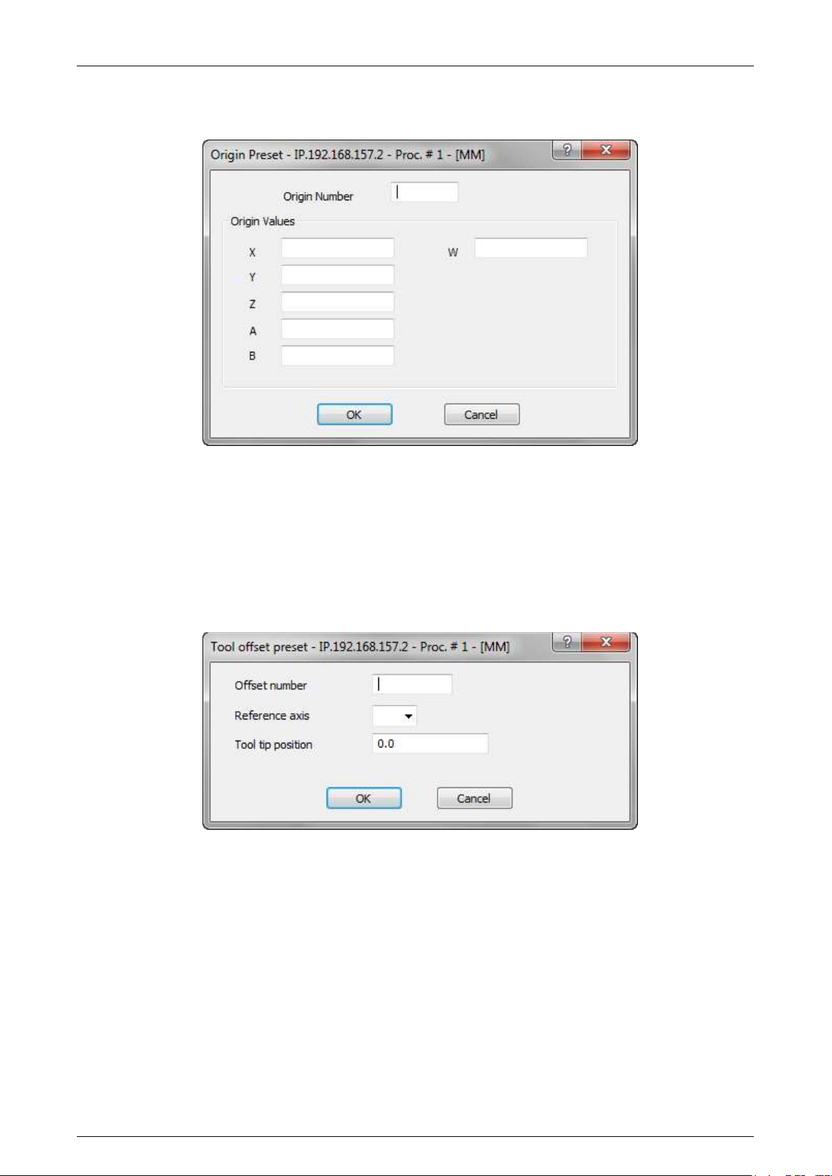
Prima Electro S.p.A. OPENcontrol – End User Manual
“Origin/Tool” – “Origin preset”
Opens an input window to define the origin values.
Origin Number
Number of the origin whose values are to be modified
Origin Values
Values of the axes to which the origin refers
”Origin/Tool” – Tool offset preset”
Opens a data-entry that allows the definition of an tool length offset
Offset Number
Offset number of the selected tool
Reference Axis
Name of the spindle axis (usually Z)
Tool Tip Position
Distance between the spindle "nose" and the fixed reference point
“Part Program” – “Activate Part Program”
Selects a part program for execution
“Part Program” – “Deactivate Part Program”
Disables the current part program.
45004602H 50
Page 51
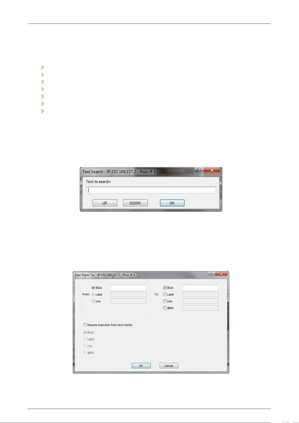
Prima Electro S.p.A. OPENcontrol – End User Manual
“Part Program” – “Part Program management”
This command enables the management of the part-programs stored on the selected CNC. The
management of the programs includes the following commands:
Selecting a program for execution.
Deselect the active program
Editing of a program.
Changing the name of a program or a directory
Erasing a program or a directory.
Create a new directory or a new program.
Copy / Paste of a program from a CNC directory to another.
Copy / Paste of a program from PC to CNC and vice versa
For a full discussion of these commands see Ch. 6 "Part Program Management".
“Part Program” – “String Search”
Searches the current program for a string of characters. The command is enabled only if a part-program
has been selected. The input window appears when the command is initiated.
After inserting the text string; each press of the <Up> or <Down> buttons will search for the occurrence
of a string in the desired direction. Press the <OK> button to terminate the operation.
“Part Program” – “Exec From To”
This command allows the definition of the part-program block (start and end) for partial execution of
the selected program. The command is active only if a part program has been selected.
45004602H 51
Page 52

Prima Electro S.p.A. OPENcontrol – End User Manual
From
To
Mode
Specified
Specified
Executes the part program between the specified blocks
Specified
Absent
Executes the part program from the block specified to the
end
Absent
Specified
Executes the part program from the current line to the
specified block
Absent
Absent
Executes from the current line to the end
Allows setting of the partial execution modes of a part program; the number of parameters inserted
determines the mode:
The starting block is defined using only one of the possible selections defined at point 3.
The conditions, described at point 4, determining the end of the program execution, can be more than
one at the same time. The field $BRK identifies the equivalent variable used in the part programs, for
this field indicate the value that the variable must have in order to finish the program.
“Utility” – Application name
The “Utility” soft-key opens a drop-down menu that allows thw launch of the other WinNBI applications
listed below.
BootController, Machine Plot, TableEditor, SystemHistory, Digicad, PathView, ODM, Calibration Tool,
TimeMonitor, Security, O-Scope, O-Scope..NET, FileBrovser
The OEM can disable these applications using the NBIconfig application.
Utility - Variables
The “Utility” soft-key also allows the opening of a data-entry for the display and change of program and
system variables.
The variables are divided by class and may be used for part-program writing, to obtain data from the
system and from the machine logic developed by the OEM. The meaning of their content is therefore
bound by the application developed for machine tool in use.
For viewing and editing of the parameters through the windows of the standard ProcessController, the
variables can be divided into two classes:
numerical variables
alphanumeric variables (texts)
45004602H 52
Page 53
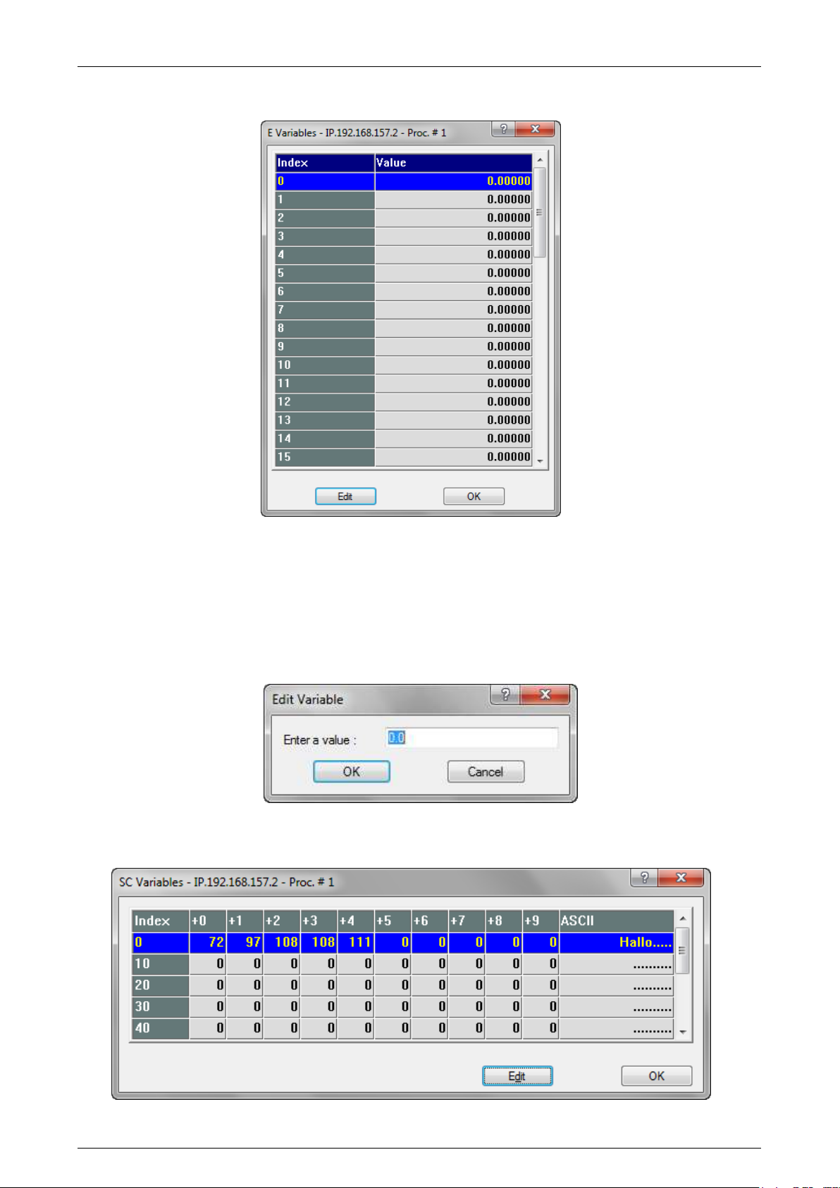
Prima Electro S.p.A. OPENcontrol – End User Manual
For a numerical variable, the Process Controller displays a panel like the one below:
The variables displayed are shown in a preset or configured length array.
To select the desired variable use the vertical scroll bar or the vertical direction keys (arrow up and
down) on the keyboard. These operations move the display window through the array and allows the
desired variable display to be selected.
To change the value of the selected variable, press "Edit", and the data entry appears, change the value
and confirm with the "OK" button.
Selecting an alphanumeric variable, the Process Controller displays a panel like the one below:
45004602H 53
Page 54
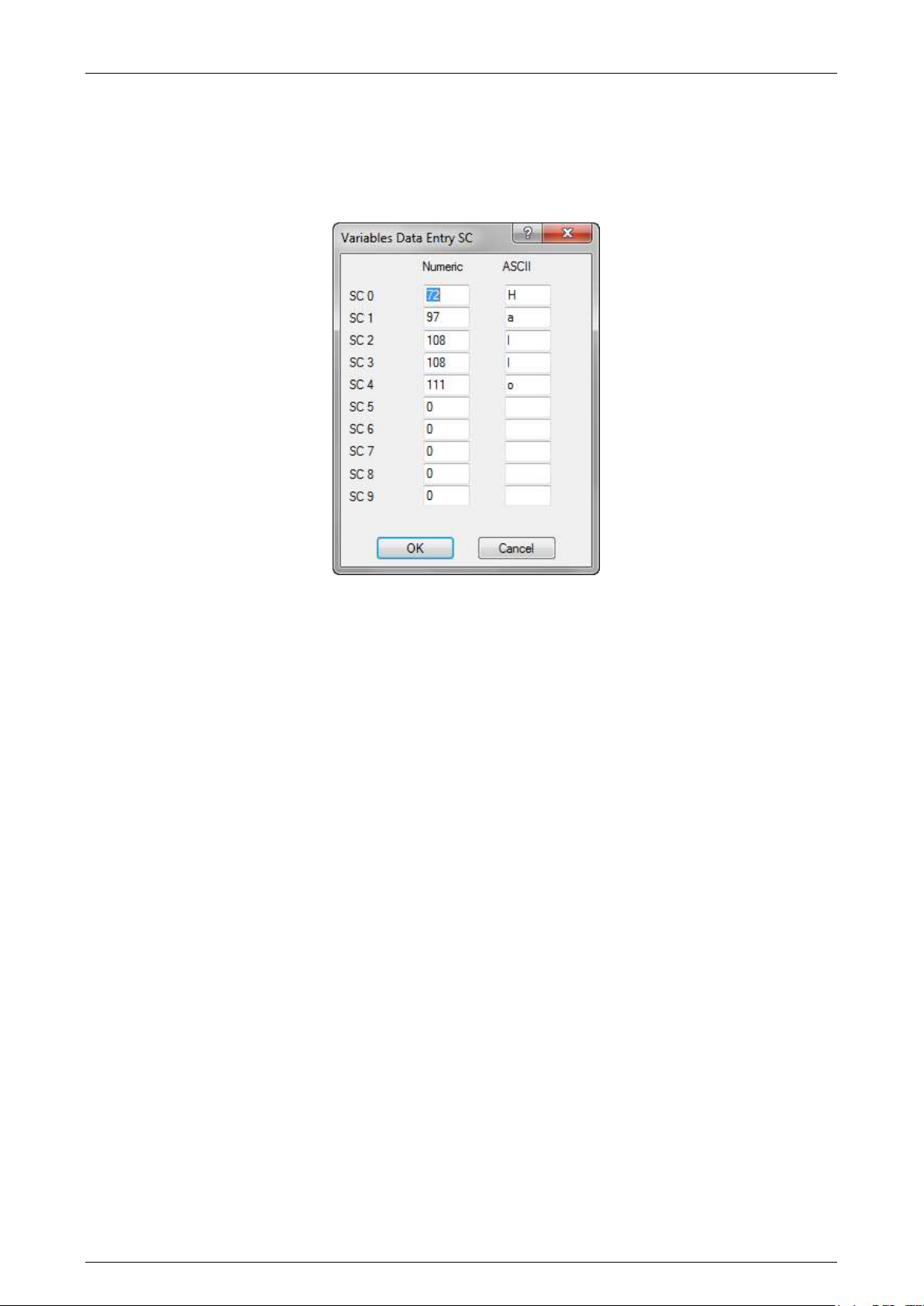
Prima Electro S.p.A. OPENcontrol – End User Manual
The alphanumeric variables are displayed in the panel with both the numerical value and the text.
To select the desired variable,use the vertical scroll bar or the arrow keys as for numeric variables.
To change the value of the selected variable, press "Edit", and in the box that appears, change the value
and confirm with the "OK" button.
The change can be done via numerical values (using the “Numeric” column) or by characters, inserting
the characters in the “ASCII” column.
Using the data-entry of the ProcessController dedicated to the variables, it is possible to view and if
allowed, change the variables E, SN, SC, User, H, Plus, Input and Output.
For additional details on the use of the variables and their format, refer to the Programming Manual.
3.8.4 MDI Panel functions
The MDI panel is used to set the command from keyboard that will be excuted by the CNC in MDI mode.
The panel automatically appears when the “MDI” working mode is selected. Using the configuration
panel, it is possible to choose how the MDI panel appears either as a basic data entry or it can be used
to store the entered commands in order to re-execute them as a part program.
There are two types of panel.
Basic MDI panel:
The "Confirm" button sends the command entered in the command editing window to the CNC.
The "Change Block" button brings the current block of the selected part-program into the command
editing window.The part-program block selection moves on to the next block.
Extended MDI panel:
When this panel is enabled, at each block “Confirm”, the command is stored in a local file (specific for
the CNC and the selected Process). Using the controls in the panel, the list of commands can be run,
edited, deleted and saved to a file of the CNC.
The "Start recording" button deletes the current storage file (of the CNC and the selected Process)
enabling the storage of the MDI commands. When the storage is enabled, an image representing a
camera is shown next to the “Confirm” button.
45004602H 54
Page 55
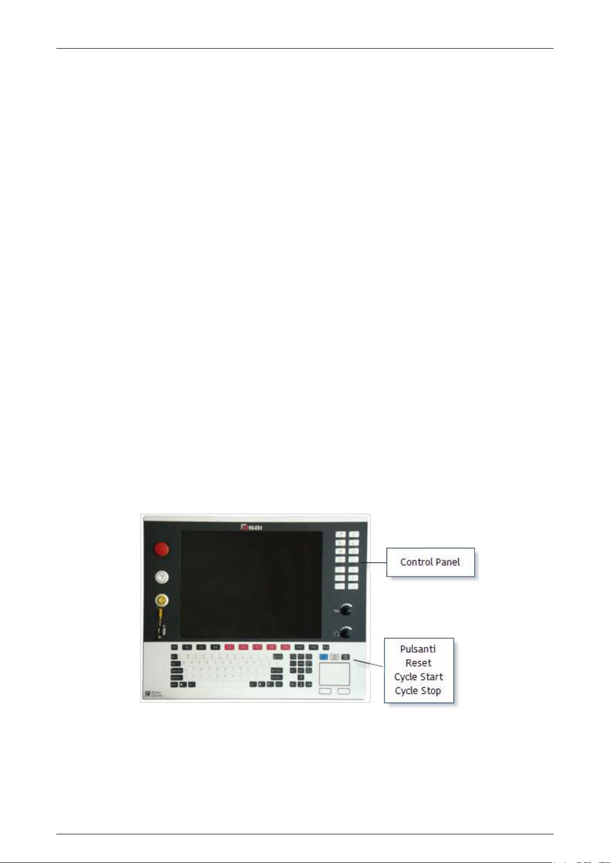
Prima Electro S.p.A. OPENcontrol – End User Manual
The button "Continue recording" enables the storage of the MDI commands without erasing the previous
ones. The new commands are appended after the existing ones. Note that the commands are stored in a
file and therefore can be inherited from previous work sessions.
The button "End recording" stops the recording of commands and enables the buttons for execution,
change and the saving of the stored commands.
The command "Delete" deletes the local storage file of the MDI commands (not the one saved on the
CNC).
The command "Change" launches the program editor configured with the configuration panel for
changing the stored command file.
The command "Save as…" saves the commands buffer to the CNC and gives them a name.
The command "Execute" starts the commands buffer execution as a pseudo-program. The buffer is
executed as a sequence of MDI commands sent from the ProcessController to the CNC. The pseudoprogram. execution can be interrupted by RESET, MODE change, STATUS change (ie hold) or error during
the execution of a block.
Operator Consoles 3.9
The Operator Console provides the operator with three control buttons for executing Cycle Start, Cycle
Stop and Reset commands, plus a series of buttons and/or selectors for changing the speed of the axes
and the mode.
3.9.1 Keys and functions of the OPENconsole COMPACT Operator Panel
As shown in the above figure, on the right side of the OPENconsole COMPACT operator panel there are
the operator console keys and the pushbuttons START, HOLD and RESET, i.e. the three control buttons
described in the section "Control Buttons" at the beginning of this chapter. The buttons on the operator
console are described below. For their functionality, refer to Chapters 5 and 6.
45004602H 55
Page 56
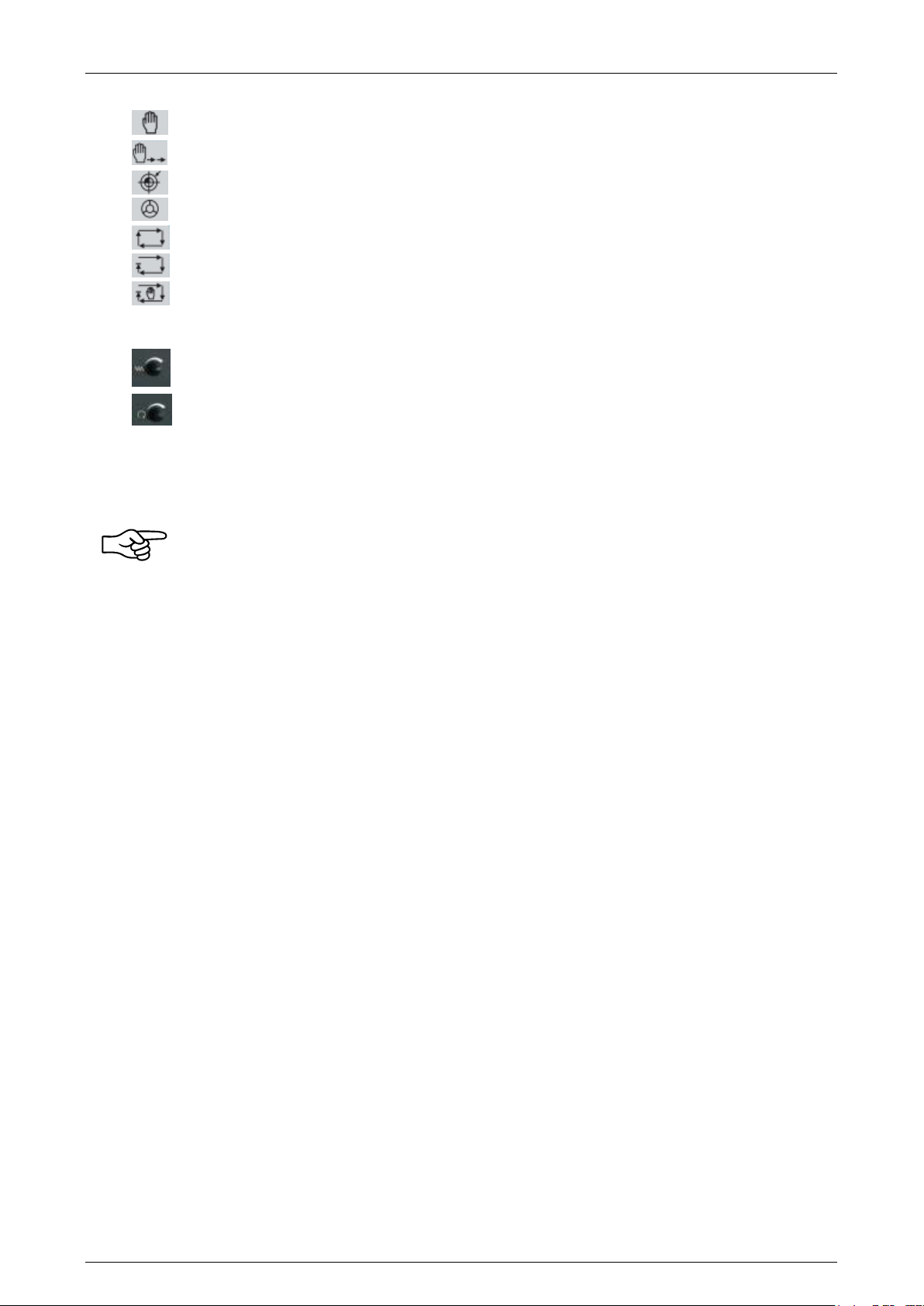
Prima Electro S.p.A. OPENcontrol – End User Manual
Enables continuous manual movements (JOG).
Enables incremental manual movements
Enables the axes homing cycle
Enables handwheel movements
Enables part-program execution in automatic mode
Enables block by block execution of the part program
Selects the MDI mode. The data entry input opens for keyboard entry of partprogram blocks.
Rotary switch for the percentage change of the movement feed of the axes in
automatic (Feed Rate Override) and manual (Manual Feed Override) modes.
Rotary switch for the percentage change of the spindle speed (Spindle Speed
Override)
The buttons from P1 to P6 can be customized with functions set by the OEM. The Cycle Start, Cycle Stop
and Reset buttons are described at the beginning of the chapter.
The functions of the buttons described here, are the standard ones managed by the system.
They can be changed through the machine tool builder’s machine logic. Refer to that
documentations.
45004602H 56
Page 57
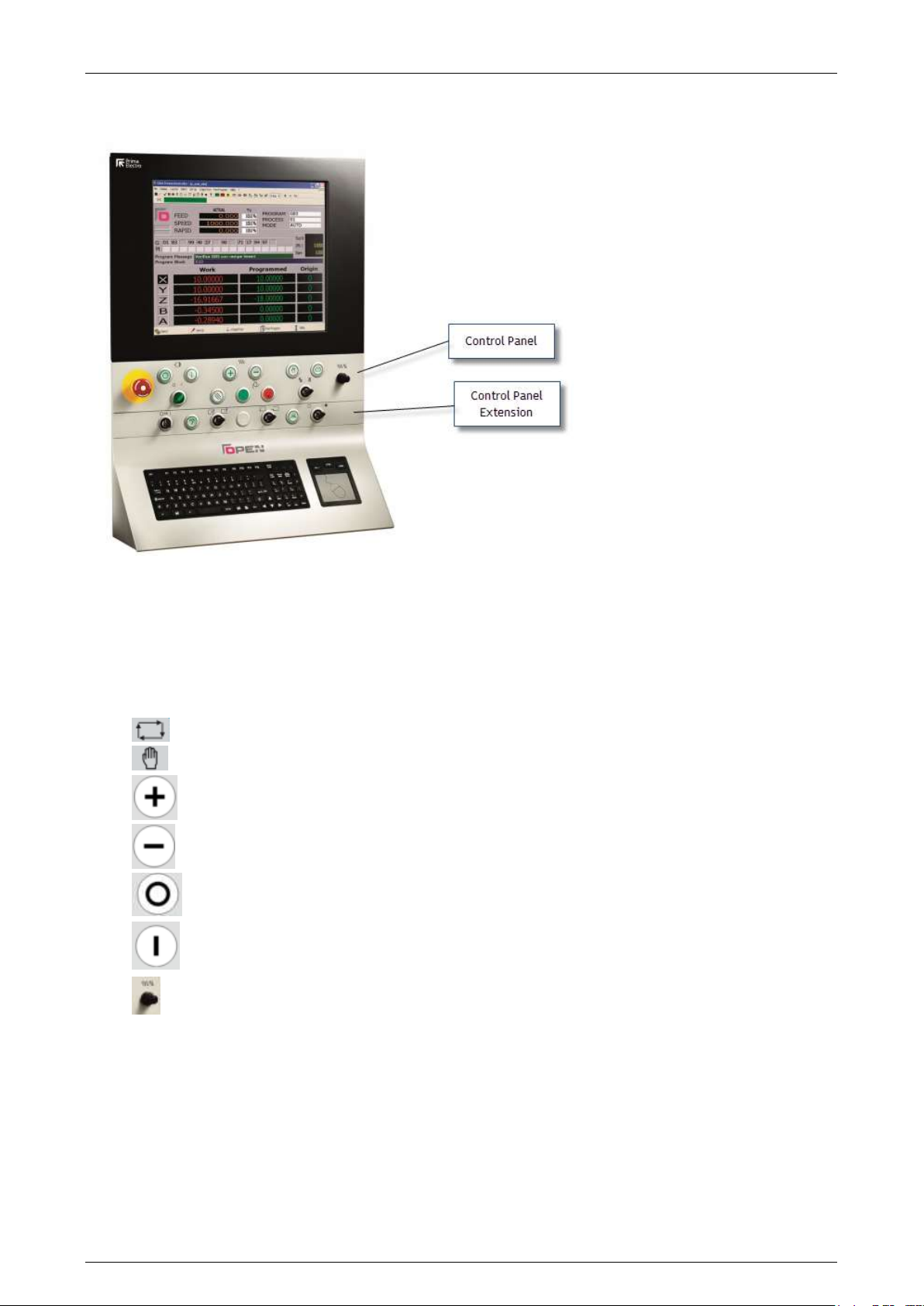
Prima Electro S.p.A. OPENcontrol – End User Manual
Enable execution of programs in continuous automatic mode
Enables the continuous manual movments (JOG).
Moves the selected axis, in continuous manual mode, in the positive direction.
Moves the selected axis, in continuous manual mode, in the negative direction.
Drive ON.
Drive OFF.
Rotary switch for the percentage change of the feed movement of the axes in
automatic (Feed Rate Override) and in manual (Feed Manual Override).
3.9.2 Keys and functions of the OPENconsole COMPACT Operator Panel
The OPENconsole is a modular Operator Panel, optimized for machine tools mainly used in Automatic and
manual continuous. The control panel can be extended with the module below that can have buttons
customized for the application.
Below are described the keys of the standard operator console (for their functions refer to chapter 5 and
6).
The Cycle Start, Cycle Stop and Reset buttons are described at the beginning of the chapter.
45004602H 57
Page 58

Prima Electro S.p.A. OPENcontrol – End User Manual
4. Establishing origins and homing the axes
General 4.1
On the machine tool you can define several reference points that allow the calculation of the axes
homing positions. The following parameters are part of the machine configuration and are set by the
MTB:
the ABSOLUTE ZERO is determined by the position of the micro switch which is placed on the
physical axis during each cycle reset
compared to the previous position, using the NULL OFFSET parameter, the MTB may require that
the zero position of each axis is moved as the quantity set: at the end of the homing cycle, on
the micro switch, the axis executes an additional movement. At the end of this movement, it
displays its position as 0.
compared to the previous position, using the HOME POSITION parameter, the MTB may require
that the zero position of each axis is moved as the quantity set: in this case, the axis does not
move physically, but its position displayed is no more 0, as it coincides with the value set having
th sign changed.
At the end of the reset cycle and the activation of the parameters previously described, it is defined
what is seen by the end user as HOME POSITION i.e. the position in which all the axes have a displayed
position equal to 0.
Axis homing procedure 4.2
Usually, after the machine boot, you can move the axes in manual mode (if allowed by the machine logic
written by the MTB), but you cannot launch a program during the execution: this will be allowed only
after following (at least once) an axes homing procedure.
If the axes have an absolute transducer, at the machine boot the axes already have a set
position referred to their HOME POSITION, therefore you do not need to perform the homing
procedure described below.
The standard procedure for axes homing follows the sequence below:
select the HOME mode
select the axis you want to home
press the CYCLE START button
wait for the end of the axis homing cycle
repeat the procedure for all the axes
If the MTB has set the mode MANUAL RESET, the operator must hold the CYCLE START button until the
end of the loop otherwise this cuts off prematurely: to complete it will be necessary to press the CYCLE
START. If you have set the mode AUTO ZERO, after pressing it you can release the CYCLE START button:
to stop the cycle must eventually be pressed the RESET button.
45004602H 58
Page 59

Prima Electro S.p.A. OPENcontrol – End User Manual
ABSOLUTE
These are the origins referred to the zero machine (HOME POSITION) and are
stored in the Origin Table. During machining, the program can recall at any
time a certain origin (via the command UAO, indicating number indicating the
identification origin number) and from that moment all the positions will refer
to this new origin. For each process can be defined up to 100 origins. For
additional details, check the Programming Manual.
In some cases, the sequence to be used for the axes homing is determined by the machine
status: for instance, let’s suppose the machine has to restart after an emergency that left
the tool in the workpiece. In this case, the operator of the machine will decide which
sequence should be used or if it’s better to manually move the axes to retract the tool from
the workpiece.
Typically, the MTB includes a complete sequence of automatic homing for all the axes, that is launched
in execution via specific commands: for this reason it is necessary to refer to the instructions of the
MTB. The procedure previously described is still valid and can be used as an alternative to automatic
one.
When the homing cycle of an axis finishes without errors, the message below appears:
22/6001 Axis homing complete
Distance micro-marker…
The value displayed for each axis in the previous message, indicates the distance between
the release position of the micro switch and the position of the market transducer: the MTB
sets the axes homing parameters so that the value is equal to about half of the mechanical
pitch.
The message allows you to check this: if this value is too close to 0 or too close to the
mechanical pitch, it could lead to a displacement error of the axis during the homing cycle
equivalent to a mechanical pitch, with consequent errors in the manufacturing. Typically,
the change of this parameter is due to mechanical causes such as the displacements of
micro switch or a slip of the motor shaft.
Definition of the origins 4.3
Usually the MYB defines some reference positions different from the HOME POSITION, in various points of
the machine (for instance, in the angles of the machining plane). In other cases, the final user needs to
define additional positions referred to other machine points, according to his requirements. All these
positions are defined as ORIGINS.
The OPENcontrol CNC allows the definition of up to 100 ORIGNIS for each process, identified by a
number from 1 to 100. The number 0 identifies the HOME POSITION origin. Each origin includes a group
of values (one for each machine axis) considered as the distance of the axis from his zero position: of
course, this value can a positive or negative sign.
The user can use three different types of origin:
45004602H 59
Page 60
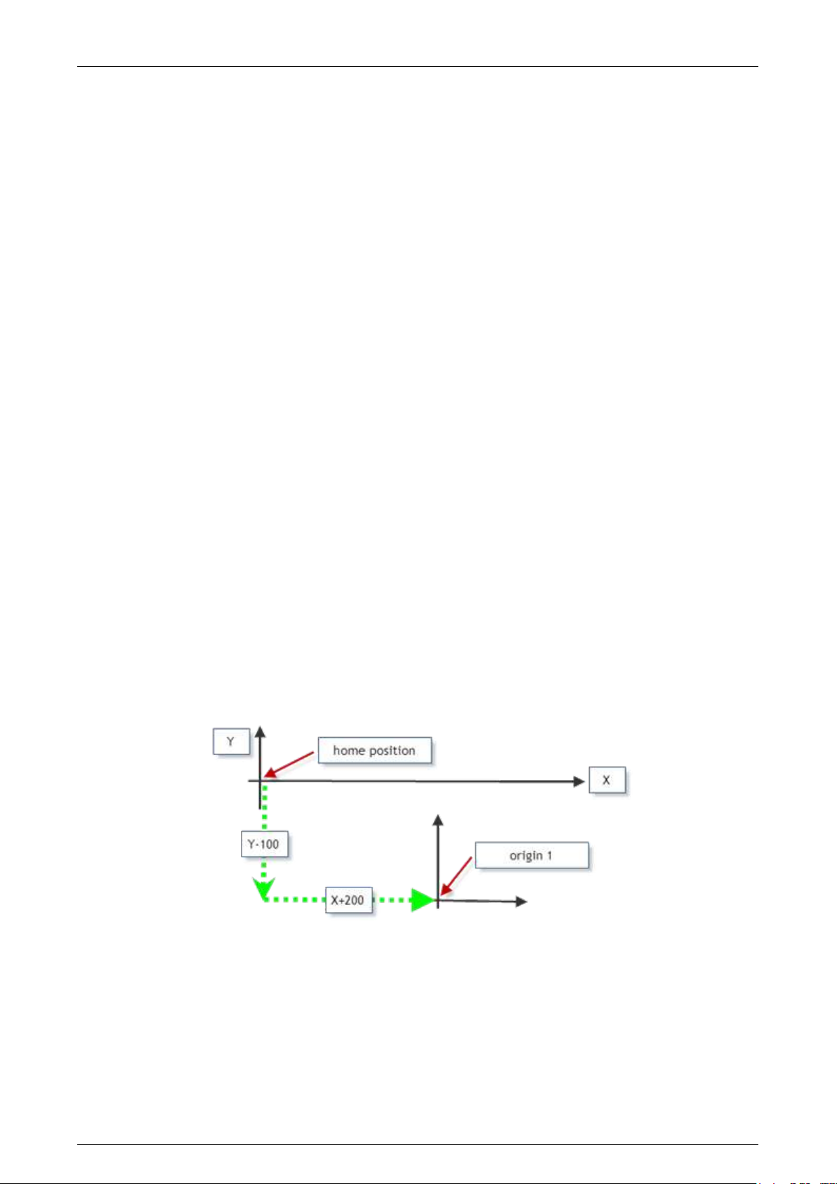
Prima Electro S.p.A. OPENcontrol – End User Manual
TEMPORARY
These are active origins, enabled by part program via the UTO command,
referred to an absolute origin of which you have to temporary modify the
value of each axis, of the quantity indicated (without changing the values
stored in the origin table). These remain active until the calling for a new
temporary or absolute origin or until the control reset. For additional details,
check the Programming Manual.
INCREMENTAL
These are origins referred to the active origin in that moment (absolute
and/or temporary), defined and enabled directly from part-program using the
UIO command. Unlike the temporary origins, where the following overwrites
the previous one, the incremental origins programmed in sequence are
summed. These remain active until the calling for a new temporary or
absolute origin or until the control reset. For additional details, check the
Programming Manual.
As aforementioned, the values to be inserted in the origin table for each axis, are considered as the
distance of the axis from its HOME POSITION. If you want to move the axis origin towards its positive
direction, the value to be inserted must have a positive sign, otherwise is negative. If the value is set =0,
the axis origin coincides with its HOME POSITION.
To set an absolute origin in the table, the user can use one of the procedures below:
1) manual setting of the absolute origin
2) automatic setting of the absolute origin
4.3.1 Manual setting of the absolute origin
In this case, it is assumed that the user already knows the value to be set for each axis and that these
values should only be stored in the CNC working area (Origin Table).
For example, you want to set the origin 1 moved of +200 in the X direction and -100 in the Y direction,
compared to the home position (see figure below).
In order to get this, after opening the origin table and selecting the origin 1, you insert a +200 value in
correspondence of the X axis and -100 in correspondence of Y axis. If you press APPLY, the values
entered are stored in the origin 1.
45004602H 60
Page 61
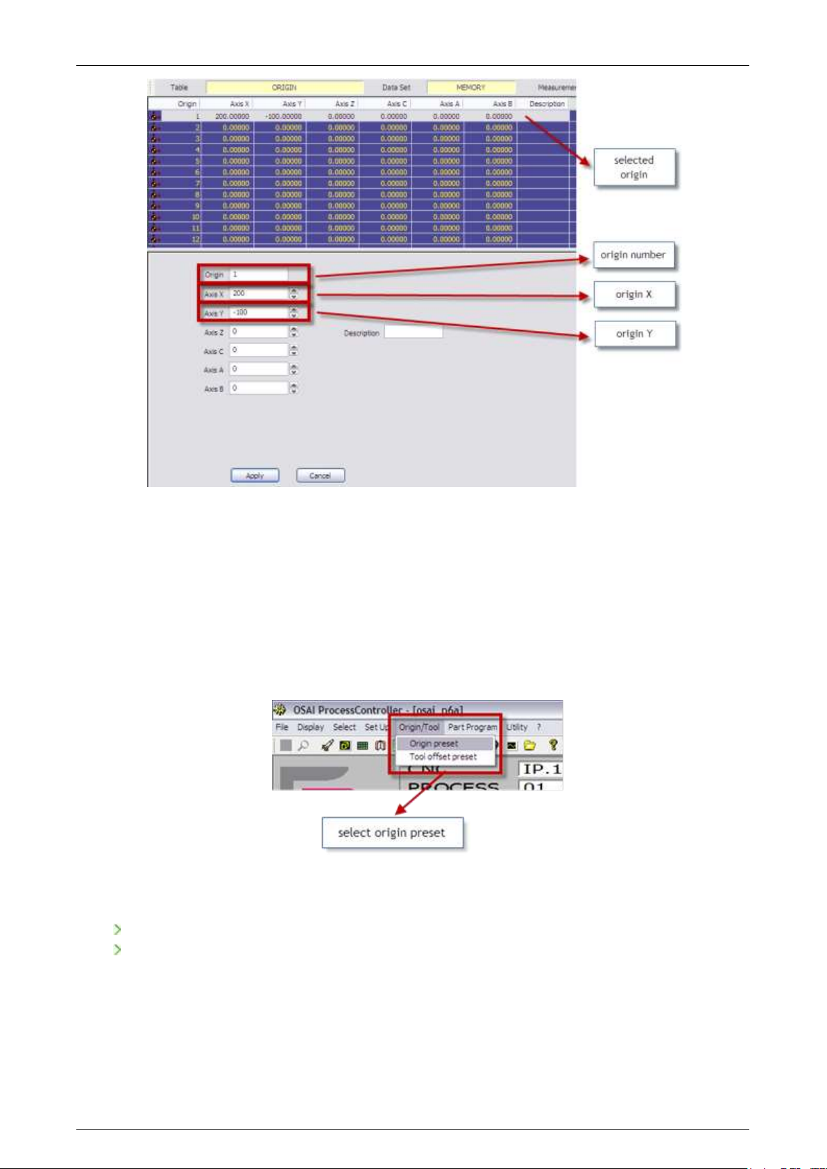
Prima Electro S.p.A. OPENcontrol – End User Manual
In this example, for the axes (ZCAB) a null origin remains set, i.e. their zero position coincides with the
HOME POSITION.
4.3.2 Automatic set of the absolute origin
The same change made for origin 1 can be automatically obtained, i.e. without opening the origin tables
editor. Without activating any origin (so that the axis positions are referred to the HOME POSITION),
physically set the X and Y axes in the positions desired (X200 and Y-100 , in our example). Select
ORIGIN/TOOL in the tool bar and then ORIGIN PRESET.
In the ORIGIN PRESET window displayed, you have to set:
ORIGIN NUMBER: the number of the origin you want to change (1, in our example)
X..: indicated axis offset with respect to the present axis position
45004602H 61
Page 62
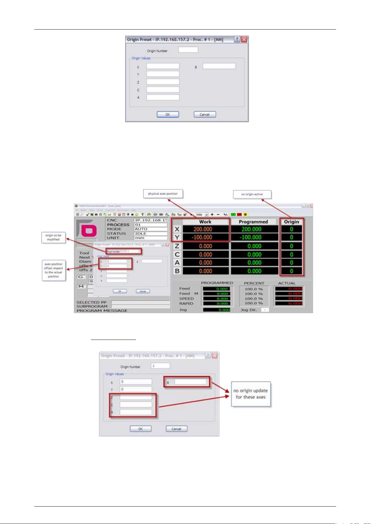
Prima Electro S.p.A. OPENcontrol – End User Manual
If you set “0” as the quote desired for the XY axes and then press “OK” and confirm, the system takes
the present axes position (X+200 and Y-100, in our example) and writes it as the value of the origin 1 in
the table. Therefore the origin 1 is physically updated with the value of the present position of the two
axes: you can verify this opening the origin editor and checking the values of origin 1 for the X and Y
axes.
For those axes where there is no value set (axis Z, C, A and B in our example) the corresponding values
set in the origin 1 are not changed.
45004602H 62
Page 63
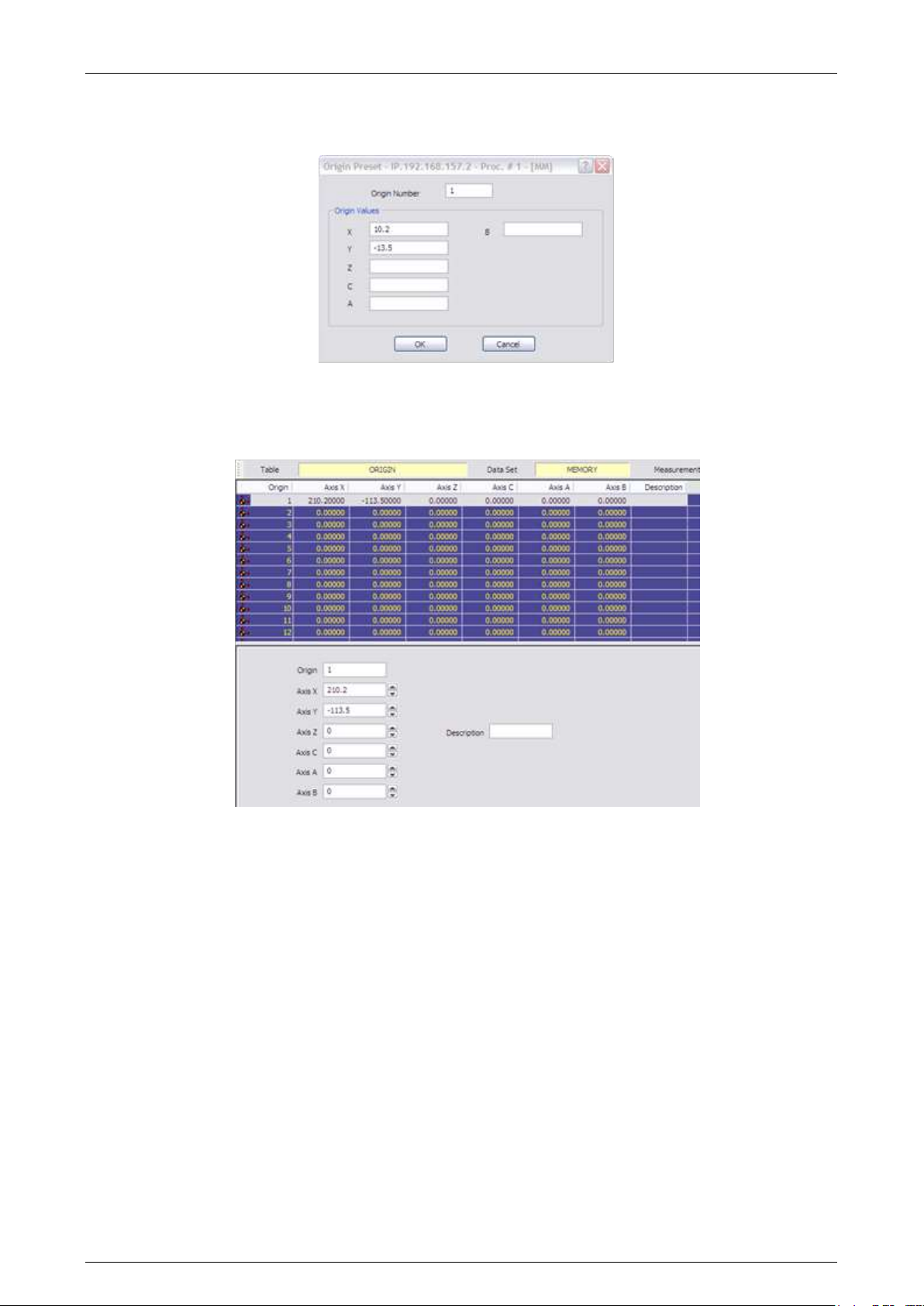
Prima Electro S.p.A. OPENcontrol – End User Manual
If in the ORIGIN PRESET window you insert values different form zero, as the example in the figure
below:
after confirming (“OK” button) the origin 1 is updated with the value (200+10.2) = 210.2 for the axis X
and (-100-13.5) = -113.5 for the axis Y, as you can verify opening the origin table editor.
45004602H 63
Page 64
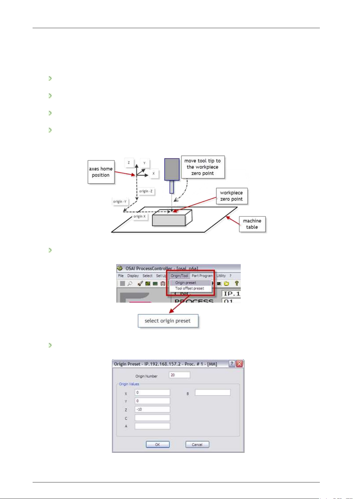
Prima Electro S.p.A. OPENcontrol – End User Manual
Axes and part origins 4.4
The part program has programmed positions referred to a reference position name PART ZERO or PART
ORIGIN. For a machining program execution, the axes origin must coincide with the origin of the part.
A simple procedure is described below:
place the raw part in the desired working position on the working plane of the machine
enable the tool offset mounted on the spindle
disable any origin so that the axes positions are referred to the HOME POSITION
manually move the machine axes until the tool tip is on the point zero of the part (the positions
displayed on the screen represent the XYZ axes positions with respect to HOME POSITION)
on the tool bar, select ORIGIN/TOOL and then ORIGIN PRESET
set the required data in the ORIGIN PRESET window
45004602H 64
Page 65

Prima Electro S.p.A. OPENcontrol – End User Manual
In our example, the origin 20 is set with 0 value for X and Y axes, while the Z axis has a -10 offset so that
the machining is made with a -10 depth with respect to the upper surface of the raw part (present
position of the tool tip).
after the confirmation, the axis positions are stored in the origin 20 of the origins table.
With this procedure, the origin 20 is correctly set and the part program can be sent to execution by
putting it in the activation of the source using the command.
(UAO,20)
The previous procedure can be made also without having the tool mounted on the spindle.
In this case, you will make the spindle nose coinciding with the zero position of the part.
Obviously, no tool offset must be activated.
45004602H 65
Page 66
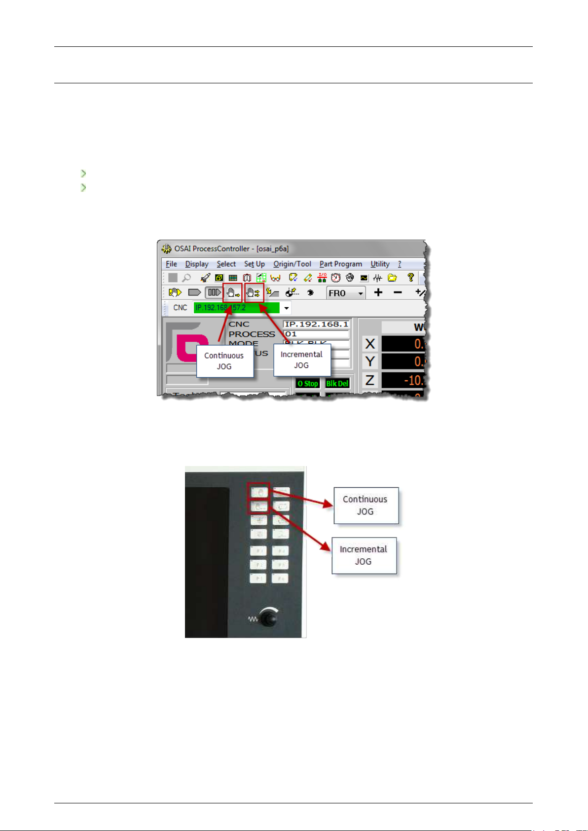
Prima Electro S.p.A. OPENcontrol – End User Manual
5. Axes jogging and Stop functions
JOG 5.1
The manual movement (JOG) of an axis can be done in two ways:
continuous jog
incremental jog
To select a jog move (continuous or incremental), press one of the two buttons in the software Operator
Panel (bar selection of the operative mode) of the ProcessController.
The same selection can be done on the OPENconsole COMPACT Operator Panel using the selection
buttons:
On the OPENconsole Operator Panel, enable the manual movements using the button and select the
continuous or incremental mode via the ProcessController.
45004602H 66
Page 67
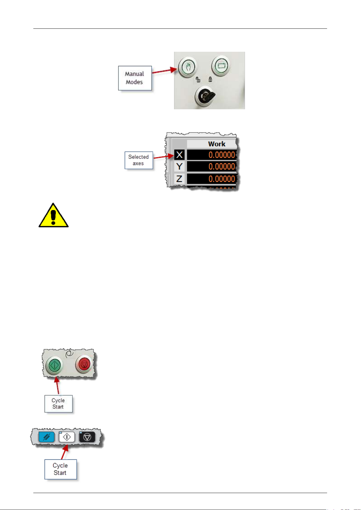
Prima Electro S.p.A. OPENcontrol – End User Manual
To select manual mode the key-switch must be turned to the position indicated by the open lock.
The axis selected for the manual movement is the one shown in reverse on the screen:
As long as the axes are not homed, the machine software overtravels are disabled. Before
doing any manual movement, it is necessary to carefully consider what movement will be
done. The machine tool builder handles the management of any hardware overtravel.
5.1.1 Continuous jog
This mode permits the axes to be jogged continuously in the selected direction at the selected rate. The
procedure is as follows: (for the execution of each command see Ch. 3):
1. Select continuous Jog mode
2. Select the axis to move
3. Select the direction of the manual movement
4. Select the manual feedrate change percentage as shown in the section "Feedrate change” of this
chapter.
5. Press the button “Cycle Start” and hold. As long as the “Cycle Start” button is pressed, the
axis moves in the direction and the speed defined.
Cycle Start button in the OPENconsole panel. The button could also be
white.
Cycle Start button in the OPENconsole COMPACT panel.
45004602H 67
Page 68

Prima Electro S.p.A. OPENcontrol – End User Manual
5.1.2 Incremental JOG
This mode allows the jogging of the axes for a pre-set increment in the selected direction at the
selected rate. To move an axis incrementally, use the procedure below: (for the execution of each
command see Ch. 3):
1. Select the incremental Jog mode
2. Select the axis to move.
3. Select the jog direction
4. Select the manual feedrate increment as shown in the section "Speed change" of this chapter
.The jog increment is set with the data-entry enabled by the softkey command . “Setup”“Manual”.
5. Set the increment value. If this step is omitted, the system will apply the current increment, i.e.
the latest one selected and displayed on the screen.
6. Press “Cycle Start”.
There are two possible incremental jog modes which depend on the JOG INCR selection in the “Setup” “Manual data-entry window:
Manual: hold “Cycle Start” button until the move is completed. If “Cycle Start” is released
before the end of the move, the axis decelerates to a stop. To continue the move press and hold
“Cycle Start”.
Automatic: in this mode if “Cycle Start” is released the move will be completed without the
axis stopping.
Manual Feedrate change 5.2
The default manual feedrate, defined by the configuration, can be changed with the following procedure
(for the execution of each command see Ch. 3):
1. In the software operator panel, use the mouse to enable the button to select the override and
select FMO (Feed Manual Override).
2. Using the buttons “+” and “-“ to the right of the selector right, increase or decrease the current
override value. Every time one of the two buttons on the screen are pressed, the percentage
increases or decreases by 1.25%. The manual feedrate change has a range between 0% and 125%.
Example:
If the value configured for the maximum manual feed is 2000 MMPM (millimetres per minute) and a 50%
percentage change, the actual manual feed will be 1000 MMPM.
Hold entry and JOG return on the profile 5.3
During part program execution, it is possible to stop machining by using the “Cycle Stop” button that
puts the system in HOLD status. In this status, the CNC allows the axes to be jogged to remove the tool
from the profile.
45004602H 68
Page 69
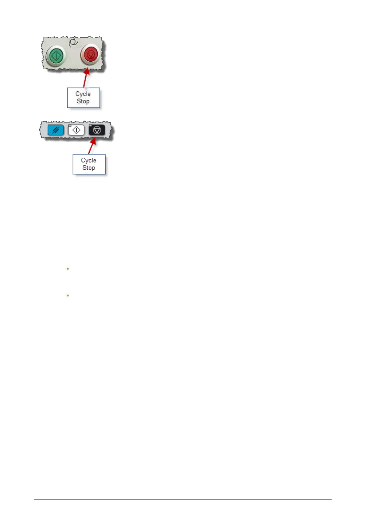
Prima Electro S.p.A. OPENcontrol – End User Manual
Cycle Stop button on the OPENconsole panel. The button could be black.
Cycle Stop button on the COMPACT OPENconsole panel.
In order to restart the part program execution, chose one of the following:
1. Repositioning of the axes to the point of interruption of the profile
Operating mode:
a) Select the axis to be returned to the profile.
b) Select the desired feed percentage of the axis.
c) Select Jog Return
d) Press “Cycle Start”.
if JOG RETURN is in "Manual" mode, keep “Cycle Start” pressed until the "AXIS ON PROFILE"
message appears; this indicates that the axis return move has been completed.
if the JOG RETURN is in "AUTO" mode, just press “Cycle Start”. The system will
automatically move ALL the axes previously displaced by following the same trajectory in
the reverse direction, so as to avoid obstructions. To abort automatic return to the profile
press “Cycle Stop”.
2. Move the axes back to the final point of the interrupted block
Operating mode:
a) In the Data Entry activated by the Softkey command “Setup”-“Manual”, select the “Skip”
option and confirm with “OK”.
b) Quit the HOLD status by pressing “Cycle Stop”.
c) Resume program execution by pressing “Cycle Start”. At this point, the axes will perform a
linear movement from their current position to the end point of the movement interrupted
in HOLD. At the end of this positioning process, program execution will be resumed
automatically.
45004602H 69
Page 70
Prima Electro S.p.A. OPENcontrol – End User Manual
This procedure cannot be performed in the following conditions:
G61 active.
Canned cycles and probe function on.
TCP with mno/ijk programming or with rotary axes in "following" mode
(interpolation with following mode).
Program block in Hold without axis movements.
In such cases, the standard execution is forced and it is necessary to move the axes
back to the profile interruption point according to procedure 1.
Spindle Speed Override 5.4
The value of the programmed spindle speed in execution can be changed with the following procedure
(for the execution of each command see Ch. 3):
1. Click on the button to select the override in the software operator panel and select SSO (Spindle
Speed Override).
2. With the buttons “+” and “-“ to the right of the selector, increase or decrease the override
value. Each time one of these softkeys is depressed, a 12.5% increment or decrement will be
applied to the programmed value. Spindle speed override percentages range from 75% to 125%.
Example:
If the maximum programmed spindle speed is 1500 RPM (Revs Per Minute) and 80% speed override is
applied, the actual spindle speed will be 1200 RPM.
Stop functions 5.5
There are various ways of stopping program execution and machine operation.
5.5.1 Reset
The reset function:
Stops axes moves.
Clears the program execution buffer.
Restores the absolute origin (Home Position).
Restores the configured G codes.
Positions the part program to the start of the file.
To perform a reset function press “Reset” on the operator panel.
Reset button in the OPENconsole panel. The button could be
blue.
45004602H 70
Page 71
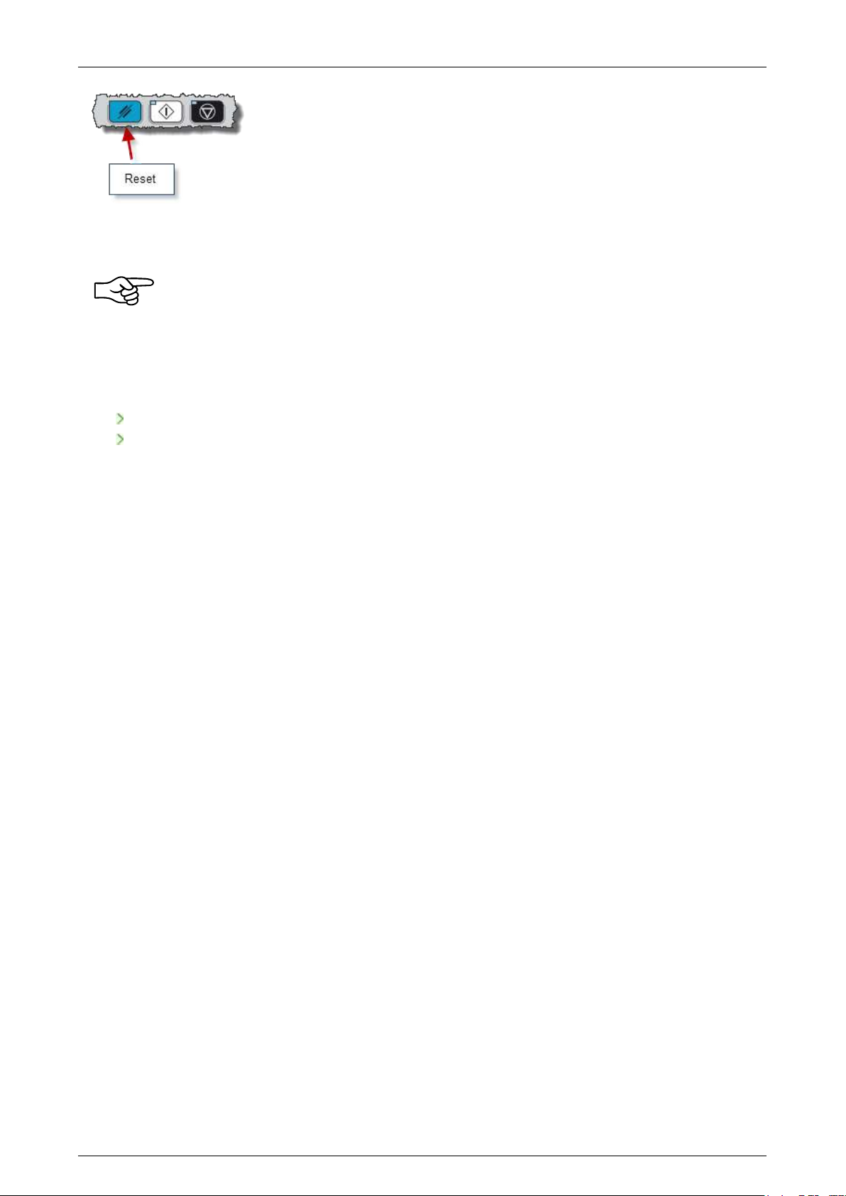
Prima Electro S.p.A. OPENcontrol – End User Manual
Reset button in the OPENconsole COMPACT panel.
Press Cycle Start to resume execution. The execution restarts from the beginning of the part program.
Depending on how the machine logic has been programmed, it may give some typical stop
commands (such as spindle stop, coolant off, etc.) when it receives the reset command.
Check the MTB manual for details
5.5.2 Hold
The hold function:
Stops the axes with controlled deceleration.
Temporarily stops program execution.
To put the axes into hold press “Cycle Stop”.
To resume execution press the Cycle Stop pushbutton again to exit from the hold condition and then
press Cycle Start. Execution will restart from the point at which the Cycle Stop command was given.
If manual moves have been performed after pressing Cycle Stop, it is necessary to re-position the axes
on the profile before resuming automatic execution. To do this, use the procedure described above.
Emergency Stop 5.6
The “Emergency Stop” pushbutton stops power supply to the system. The “Emergency Stop”
pushbutton is not managed by the software system of the CNC and is controlled by the machine tool
hardware. It is mounted on the Operator panel or in other parts of the machine tool.
Active reset 5.7
This command is available only in the WinPLUS logic program. It can be used after a cycle stop in order
to cancel either the remaining portion of the current motion block or the subsequent part program
blocks.
To allow automatic active reset, with WinPLUS the active reset function is available on an external
pushbutton or on machine devices. For example, if a gap elimination device detects the contact
between the tool and the part.
a) it resets the interrupted move.
b) searches the subsequent program block for execution. This block will be calculated from the
current position.
c) executes assignment blocks, three-letter code instructions, branching instructions, etc. during
the search.
d) after the subsequent move has been terminated, the ACTIVE RESET function is reset and the
system does not re-launch the part program.
45004602H 71
Page 72

Prima Electro S.p.A. OPENcontrol – End User Manual
If there is a part program selected, the active reset command is allowed if the system is in IDLE status
and the procedure is the same as those described above apart from point a).
If an active reset command is given when the system is neither on HOLD nor in IDLE status, the following
error message will be displayed: "Command not congruent with the system status".
Active reset can be given in AUTO, MDI and BLK/BLK. If the control is in any other mode, the following
message will appear: "Bad selected mode". If MDI (Manual Data Input) mode is active, active reset will
only reset the interrupted move. All the instructions that have not been transferred to WinPLUS will be
lost.
if active reset is allowed but the interrupted block is not a point to point move with linear or circular
interpolation, the "active reset not permitted" message will be displayed. if the interrupted block has
been stopped at the end of interpolation, the active reset command will be ignored.
The subsequent block must be a linear move (G1); if it is not, the "Active reset not permitted" error
message will be displayed. If the subsequent block is a contouring move (G27/G28), the active reset
function will be allowed but the new block will be executed as a point to point move.
All the M, T, S and logic functions that are programmed in the interrupted block or in subsequent blocks
and have not been transferred to WinPLUS will be lost.
The new block calculated by the ACTIVE RESET command contains the coordinates of the axes
programmed in the subsequent block. If the active reset command has been executed successfully, the
system switches from HOLD to HOLD RUN (HRUN). The red LED turns off and the system awaits a “Cycle
Start” command.
If an active reset function generates an error (for example, if the cycle start coordinate coincides with
the subsequent motion block) the system remains in hold (red LED ON) but part program execution does
not resume when you give a “Cycle Start” command. All the subsequent active reset functions will be
allowed and the error will be removed.
Since during an active reset the system reads and executes part program blocks, some of the errors
displayed may be numerical control errors. however, the "end of file" message is not an error but a
signal. When this message occurs, the system status does not change to HRUN and “Cycle Start” permits
execution of the block that has been restored after one or more active reset commands.
When the active reset function is not accepted by the system, further active request commands shall be
taken to refer to the following blocks and, in the absence of errors, the active reset function for such
blocks shall be accepted.
The block-end M functions programmed in the interrupted block will be "forgotten" after an active
reset. Execution of the subsequent block will start when the “Cycle Start” command is given. If other
active reset commands are given, the M codes programmed in these blocks will also be ignored.
G29 G01 X100 M05 Active reset at X=50 (M05 will be ignored)
G01 Y100 M06 Active reset (M06 will be ignored)
G01 M03 Y100 M05 Cycle start :
1. M03
2. Move to X50 Y100
3. M05
45004602H 72
Page 73
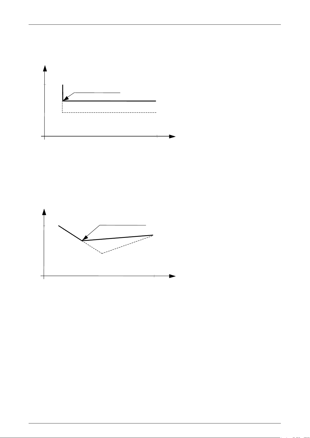
Prima Electro S.p.A. OPENcontrol – End User Manual
100
40
HOLD, reset attivo
percorso nuovo
percorso originale
Y
X
100
40
percorso nuovo
percorso programmato
HOLD, reset attivo
Y
Any active reset function accepted by the system will enable the subsequent block. This can be observed
on the display, where the enabled block will appear in reverse mode.
Example 1
X10 Y40
Y20 Active reset during execution of this block
X100 Y30 X100 at the end of this block
Example 2
X10 Y40
X50 Y10 Active reset during execution of this block
X100 Y30 Y30 X100 at the end of this block.
45004602H 73
Page 74
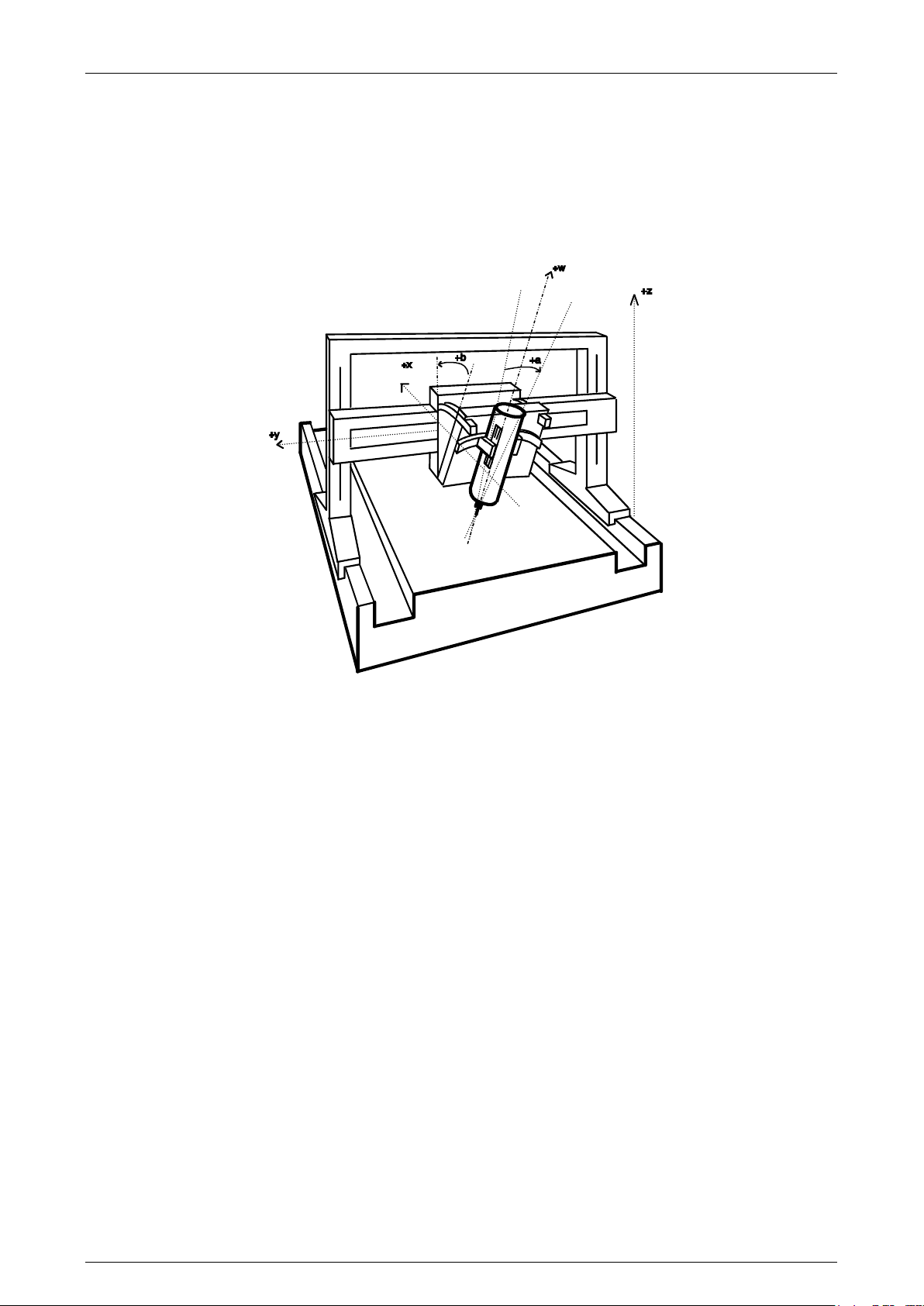
Prima Electro S.p.A. OPENcontrol – End User Manual
Removing the tool after an Emergency 5.8
In some special applications (such as a 4- or 5-axis machines performing inclined machining in which the
moves in the direction of the tool axes are the result of interpolations by other axes), execution may be
interrupted by an emergency stop (voltage drop, general emergency, etc.) or by a programmed stop
followed by manual moves.
An example of this is shown in the picture below.
This machine has three normal axes (X, Y and Z) and two rotary axes that incline the spindle carrier
head.
When an emergency stop occurs, it sometimes happens that the tool remains inside the part. To remove
the tool from the part after the machine has been re-powered up, the system must offer you the
possibility to move the spindle in the tool direction. This can be useful in case the tool remains stuck in
the part during machining.
The system automatically defines the virtual axis whose name must be previously characterised in AMP.
Movement of this virtual axis causes the linear axes to move, so that the tool moves in the linear axes
direction, i.e. in the direction indicated by the position of the rotary axes.
The generation of the virtual axis along which the axes movement is required is set via the “Tool
direction” field in the data-entry “Manual Setup” enabled by the softkey command “Setup” –
“Manual”.
45004602H 74
Page 75
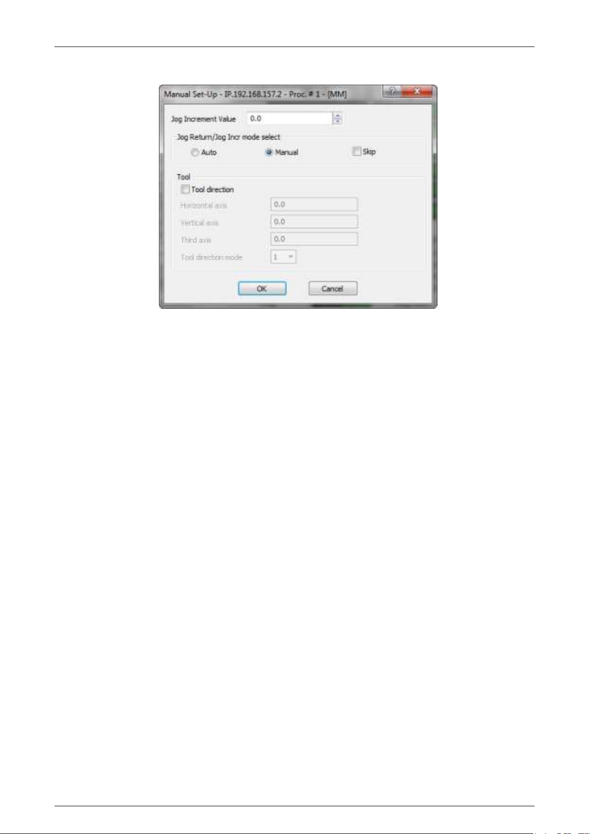
Prima Electro S.p.A. OPENcontrol – End User Manual
The procedure is:
1. Open the data-entry “Manual Setup”:
2. Tick the field “Tool Direction”
3. If necessary, change the positions related to the (max) three rotary axes.
4. Check and if necessary correct the positions of the rotary axes and the selection of the Tool
Direction Mode
5. Confirm with “OK”. At this point, the system generates the virtual axis for the movement of the
axes along the tool direction or the axes of its plane (see below).
The three fields are editable, allowing e.g. to change the direction of tool output or input the correct
positions of the axes that may have been moved between the time of the anomaly and when the "Tool
direction " mode is activated.
Horizontal axis
Value in degrees of the position of the horizontal rotary axis (described as “Work rotary axis” in AMP)
Vertical axis
Value in degrees of the position of the vertical rotary axis (described as “Tool rotary axis”.in AMP)
Third axis
Value in degrees of the third rotary axis (described as “Middle rotary axis”.in AMP).
The values of the three fields can be changed only before the execution of the cycles reference axes.
Tool Direction Mode
Allows enabling of the axes movement along the tool direction and its reference plane. In AMP three
virtual axes are configured (see Kinematics), one along the tool direction and two related to the plane
fixed to the tool direction.
The value 1 only enables the tool direction axis.
The value 2 enables both the axes.
The value 3 enables all the axes, but the reference plane does not comply with the tool direction, but
complies with the machine plane.
45004602H 75
Page 76

Prima Electro S.p.A. OPENcontrol – End User Manual
NOTE:
If only one of the rotary axes is referred, the system displays the position corresponding to the one not
referred: the previous considerations remain valid. See also the Tool Centre Point, mode 5, in the
Programming Manual.
The functions described in this chapter are the system standard. They can be changed by
the machine tool builder’s machine logic. Refer to the MTB documentation.
45004602H 76
Page 77
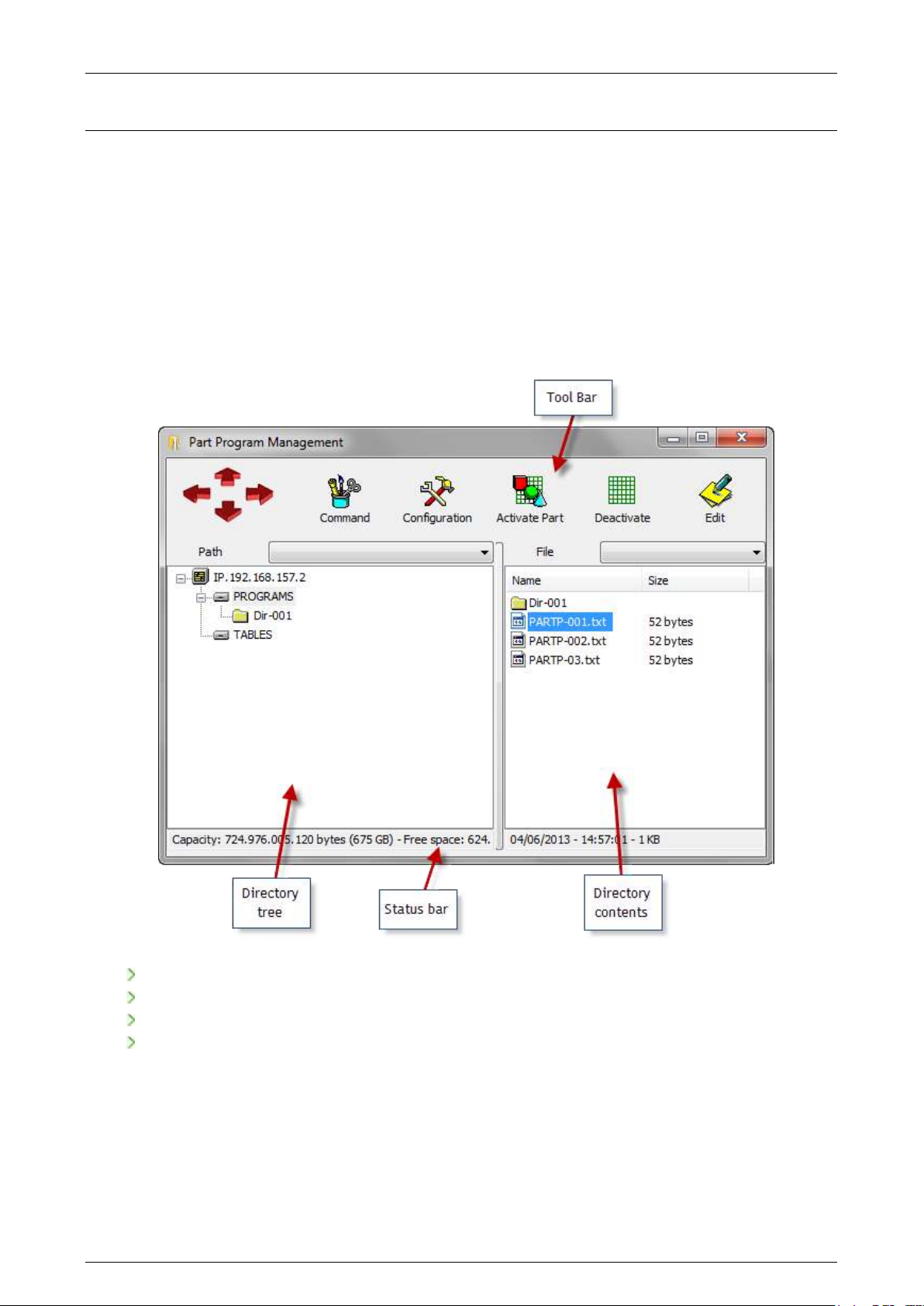
Prima Electro S.p.A. OPENcontrol – End User Manual
6. Part Program Management
The OPENcontrol CNC has an ambient dedicated to the part program file management, that can be
distributed in several directories. The program management ambient is therefore the file manager that
activates the program and also allows the management of the files and system directories.
Main Video Screen 6.1
Pressing the “Part Program” softkey of the ProcessController and then selecting “Part Program
Management”, the ambient screen video is displayed:
The video screen is divided in 4 functional areas:
Directory Tree
Directory Contents
Tool Bar
Status bar
“Directory Tree” Area
As a reversed tree, in this area are displayed the devices and their content. Starting from the root, each
branch represents a device (CNC/GMC/PC). The sub-branches are the directories contained in the
device. This area displays the files contained in the directories. The content of the selected directory
(file or other directories)is displayed in the “Directory contents” area.
In this chapter, the area is also indicated as “left panel”.
45004602H 77
Page 78

Prima Electro S.p.A. OPENcontrol – End User Manual
“Directory Contents” area
This is the area displaying the content of the directory selected in the left panel. It lists the directories
and the files. Selecting a directory in the left panel, the content of this read is automatically updated.
In this chapter, the area is also indicated as “right panel”.
Toolbar
It contains the command to be applied on the directories and on the files. The commands available in
the toolbar are also available selecting a directory or a file with touch-pad right-click.
Status Bar
It contains the data referred to the selected element.
If a logic drive is selected in the Directory Tree area, the status bar below displays the capacity and the
free space. If in the Directory Contents area is selected an element, the status bar below displays the
time and date of creation for the directories; instead displays the date, time of creation and size for
files.
Selection of an item 6.2
Usually, the several commands available in the Program Management, refer to the “selected element”.
The selected element is the device, the file or the directory displayed in reverse in the “Directory Tree”
or “Directory Contents” areas. To select an item, you can use touch-pad and selection keys, those from
keyboard or those graphic in the Toolbar of the Program Management.
If using the touch-pad, once the cursor is on the element, left-click.
Multiple selection 6.3
In the right panel it is possible to select several items. This allows the simultaneous application of a
command to all the selected elements (for instance, the delete and drag&drop copy commands). A
selected item is displayed in reverse.
The multiple selection, always done in the right panel, can be done is different ways:
Method 1, for close items, touch-pad selection:
Select the first element using the touch-pad
Hold the “Shift” button of the keyboard and select with the touch-pad the last element
All the items included between the first and the last are selected
Method 2, for close items, selection with the arrow keys “Up” and “Down” on the keyboard:
Select the first element using the touch-pad
Press the “Shift” pushbutton and press several times the key “Up” or “Down”. each time you
press either button, a file form selection is added or removed (according to the selection of the
movement with respect to the first element)
Method 3, for discontinuous elements:
Select the first element using the touch-pad
Press the “Ctrl” key and select with the touch-pad another element, not necessarily close to the
previous one. If you select an element already selected, the element is removed from the
selection.
All items selected individually, are added to the selection.
45004602H 78
Page 79

Prima Electro S.p.A. OPENcontrol – End User Manual
Creation of a new Part Program 6.4
To create a new part program:
select in the left panel the directory in which you want to create a new file.
right-click on the touch-pad in an empty area of the right panel. Select “Create File” from the
drop-down menu.
In the directory is created the “NewFil##” file. Where ## are two digits used to differentiate
one file from the other in case more than one file is created without renaming them. The first
file will be NewFil01, the second NewFil02 etc.
The field containing the name of the file just created is opened for editing. Write the new name
and press “Return” on the keyboard, or select another element form the screen with the touchpad and confirm the new name; to exit the editing and restore the original name, press “ESC” on
the keyboard.
To write the program in the file, see “Edit” command
Creation of a new Directory 6.5
The procedure is very similar to the one used for the creation of a new file.
To create a new part program:
select in the left panel the directory in which you want to create a new file.
right-click on the touch-pad in an empty area of the right panel. Select “Create Dir” from the
drop-down menu..
In the directory is created the “NewDir##” file. Where ## are two digits used to differentiate
one file from the other in case more than one file is created without renaming them. The first
file will be NewDir01, the second NewDir02 etc.
The field containing the name of the file just created is opened for editing. Write the new name
and press “Return” on the keyboard, or select another element form the screen with the touchpad and confirm the new name; to exit the editing and restore the original name, press “ESC” on
the keyboard.
To write the program in the file, see “Edit” command
45004602H 79
Page 80
Prima Electro S.p.A. OPENcontrol – End User Manual
File copy and directory 6.6
To copy a file or a directory:
Search, via the left panel, the directory containing the element to copy and select it.
right-click on the touch-pad in the right panel once the cursor is on the element name to be
copied.
Select “Copy”
Using the left panel, select the destination directory.
right-click on the touch-pad in an empty area of the right panel. Select “Paste” in the drop-
down menu.
If the destination directory coincides with the one of the element to be copied, the element is copied
and automatically renamed, adding in the end of the name a progressive number.
To copy on e or more files or directories, it is also possible to “drag&drop”, i.e. using the touch-pad,
drag the file name from the directory location to the destination one.
The procedure is:
Open the destination directory in the left panel.
In the left panel, search the directory containing the file and copy it.
Left-click on the touch pad after placing the cursor on the file to be transferred, hold the
pushbutton (the multiple selection can be also used to move several elements at the same time –
see paragraph “Multiple selection”)
Using the touch-pad, drag the icon up to the destination directory in the left panel
Release the touch-pad button.
This can be simplified by using the configuration screen in four quadrants. See the explanation of the
“Quad View” command.
Delete a directory or a file 6.7
To delete a file or a directory:
Using the left panel, search the directory containing the file or the directory to delete.
right-click on the touch-pad, in the left or right panel, after placing the cursor on the element
to delete.
Select “Delete”
If the element to be deleted is a directory, an additional confirmation to delete the content is
required.
To delete a directory and several files at the same time:
Using the left panel, search the directory containing the file or the directory to delete.
Multiple selection of file in the panel (see “Multiple selection” paragraph).
Press “Delete” on the keyboard.
Before deleting the selected elements, the systems requires a confirmation.
The file and the directory are permanently erased. When deleting a directory, all its content
is erased (files and sub-directories).
45004602H 80
Page 81
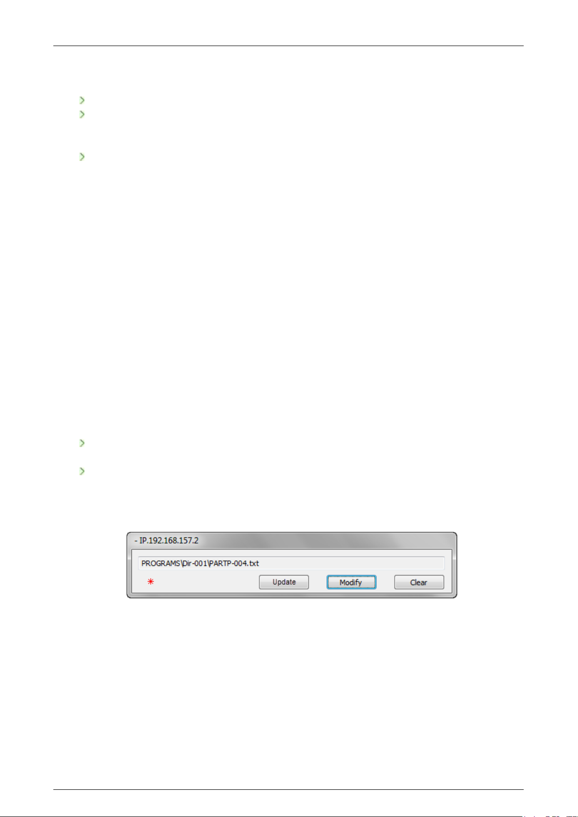
Prima Electro S.p.A. OPENcontrol – End User Manual
Change the name of a file or a directory 6.8
To change the name of a file or a directory:
Using the left panel, search the directory containing the file or the directory to rename.
Right-click on the touch-pad in the right panel on the item to rename and select “Rename”.
Alternatively, select the item with the left button of the touch-pad, wait 2 seconds and select it
again.
The field containing the name of the item passes in “Editing” mode. Write the new name and
press the “Return” pushbutton on the keyboard or select another video item with the touch-pad
to confirm the new name; exit the editing and restore the original name, press “ESC” on the
keyboard.
Writing and editing a Part program 6.9
The part-programs are text files in ASCII format and can be edited with any Editor that does not change
their format. The file can be defined or edited on the CNC or, offline, on a PC and then copied in the
control. The Online Editor used by the CMC depends on the configuration set by the OEM using the
WinNBI configuration application “NBIconfig” password-protected.
In the configuration released by Prima Electro the pre-set editor is Microsoft WordPad.
For the Editor use, refer to the documentation provided by the application provider.
The edit of a par program is always done on a copy of the program. The file opened for editing is
previously duplicated (the file is moved from the CNC to the PC in case the system hardware
configuration has a PC dedicated to the HMI or is copied in a temporary directory in case the
configuration has only one CNC module).
This has two advantages:
it is possible to work on the PC HMI system in the same way as on the system having only the
CNC
allows the file editing even if it is selected for the execution (see further on)
The Program Management includes a panel for managing the temporary file in editing (see picture
below).
The “Update” button applies the changes made. It is enabled only when the date/time of the file in
editing are changed compared to the original, i.e. after saving the file changes done with the editor.
Enabling the button, the original file is overwritten with the temporary one and the panel is closed. This
command cannot be completed if the file is busy with other programs. Same thing for the program
enabled for the execution. Before updating the program in execution, close it.
The button “Modify” re-opens in editing, Pressing this button the editor re-opens to edit the temporary
file. The button “Clear” resets the changes made to the temporary file. Pressing this button, the
temporary file is deleted and the panel closed.
45004602H 81
Page 82

Prima Electro S.p.A. OPENcontrol – End User Manual
The program “Program Management” can be closed also if the panel to manage the program editing is
opened. When re-opening the “Program Management”, the panel is displayed to complete the editing
operations.
In the panel, the button to be used by the user is blinking. Until the file has not been edited, the button
“Modify” blinks, following the first edit, the button “Update” blinks. Therefore, when the “Update”
button is blinking, it indicates the file has been edited form the original one.
Follow this procedure to edit a part-program:
If the file does not exist already, create it following the procedure “Creation of a new Part
Program”
In the right-panel, select the file to edit.
Press “Edit” in the Toolbar.
The part-program opens in editing using the configured editor.
Edit the file, save it and close the editor.
In the panel described above, overlapped to the Program Management, select “Update”.
The file is edited and updated on the CNC.
To execute several editing sessions on the same file, i.e. to re-edit a file once closed and before the
updated execution, use the “Modify” button in the panel to manage the temporary file instead of
“Edit”.
Enabling a Part-Program for the execution 6.10
To execute a Part Program, it must be selected and enabled.
The CNC reads the part-program from the file selected, that remains busy in reading until the command
“Deactivate” is released.
To enable a part-program:
in the left panel, select the directory containing the file.
in the right panel, select the file name
press “Activate” in the Toolbar.
The name of the program activated and its firs lines, are displayed in the video screen of the
ProcessController (if available in the selected video).
This procedure enables the program, but does not execute it.
The procedure to execute the program is described in the Ch.7 “part Program Execution”.
Disabling the Part-Program selected 6.11
To disable the selected program for the execution, press “Deactivate” in the Toolbar. It is not necessary
to select the file with the touch-pad to execute this operation. The CNC allows the deactivation of the
program only in IDLE status.
45004602H 82
Page 83

Prima Electro S.p.A. OPENcontrol – End User Manual
Program Management Configuration 6.12
The Program Management works on the configured devices. The Program Management displays in the left
panel all the devices configured and allows the execution of the operations described in the previous
paragraphs (also between devices). For example, it is possible to execute the copy drag&drop of a file
from a CNC to another of from a PC to a CNC and vice versa. By "device" is meant an OSAI CNC or GMC,
or even a PC or a Teach Pendant.
The "Add device" command is available in a drop-down menu that is displayed by clicking the
“Configuration” button in the Toolbar. This command only requires the network name of the device that
you want to connect. When a device has been connected, the Program Management is able to view all
the relative drives configured.
NOTE:
In the panel opened by “Add Device” command the network name or the TCP/IP address of the device
must be specified adding the prefix "IP." For instance, if you want to connect an OPENcontrol CNC whose
network name is "OPEN-XS_001" and whose network address is "192.168.1.26" in the device connection
panel you may write either “IP.OPEN-XS_001” or “IP. 192.168.1.26”.
To select a local device, i.e., the device where the Program Management is active is active you may use
the prefix "IP."
Please note that a device can be a PC (local or remote) making possible to use it a Part Program
repository from where the programs are copied to the CNC executing them.
When the PC is the one running “Program Management” simply add to the configuration the “IP.” device
to access the configured PC logical drives (see below).
By default the Program Management connect the device selected by ProcessController. The user is not
required to configure this device.
The devices connected by the user with the “Add Device” command remain in the Program Management
configuration on a permanent basis and are connected again each time the application is launched.
To remove a device from the configuration select the device name in the Directory Tree panel and press
the “Configuration”. In the drop down menu select the “Remove Device” command.
The visualization of device will be removed from the Directory Tree but the contents of the device will
be unchanged.
Logical drive configuration 6.13
All drives shown for each device in the Directory Tree are directories that have been configured on the
target device. The drives are simply a name assigned to a directory of the device. This is way they are
called “logical drives”.
Enabling the configuration gives access to commands that make it possible to add or remove logic drives
on all the devices configured. It is possible to create logical drives on each device connected by
“Program Management”, also the remote one with the exception of the PC device. In the last case, for
privacy reasons, to be able to create a logical drive, Program Management must run on the PC itself (see
the warning below).
The “Enable Configuration” command is available in a drop-down menu that opens when you click
“Configuration” button in the Toolbar.
45004602H 83
Page 84

Prima Electro S.p.A. OPENcontrol – End User Manual
To access the configuration you must enter the OEM password.
The predefined password of WinNBI is "OEM".
The possibility to change the configuration remains active, without the need to re-enter the password,
until the Program Management is closed.
6.13.1 Adding a logical drive
The command "Add logical drive” is available in the drop-down menu that is opened by clicking the
“Configuration” button in the Toolbar, when a device is select in the Directory Tree.
In the panel that opens activating the command, you must enter the logic name of the drive (which users
will see in the Directory Tree) and the absolute route of the directory to be associated with the drive.
The route must be valid for the device referred to. For example, "\SSD\USER\PROGRAMS" could be a valid
route for OPENcontrol while “C:\PartPrograms” could be the valid route for a PC.
The specified directory must exist on the selected device.
The configuration resides in the (local or remote) selected device that is being configured,
and is read by the Program Management when activated, and therefore the logical drives
added to the configuration of a device are visible in the network by all the other admissible
OSAI devices.
For data security purposes, it is NOT possible to configure a drive on a remote PC. The drives that you
want to configure on a PC must be configured by launching the Program Management (or the
“FileBrowser” WinNBI application) residing in the PC itself. In other words, only a user authorized to
work on a PC may decide which directories, if any, will be visible to the other network devices.
6.13.2 Removing a logical drive
This "Remove logical drive” command becomes available only when the configuration has been enabled
with the "Enable configuration" command.
The command is in the drop-down menu that is opened by clicking the Configuration button in the
Toolbar when a drive is selected. Upon being confirmed, this drive is removed from the Directory View
and from the configuration. All drive contents on the target device will remain unchanged.
6.13.3 Showing logical drive path
The “Show logical drive path” command displays the physical path configured for a logical drive.
This command becomes available only when the configuration has been enabled and when a drive is
selected in the Directory View panel.
45004602H 84
Page 85
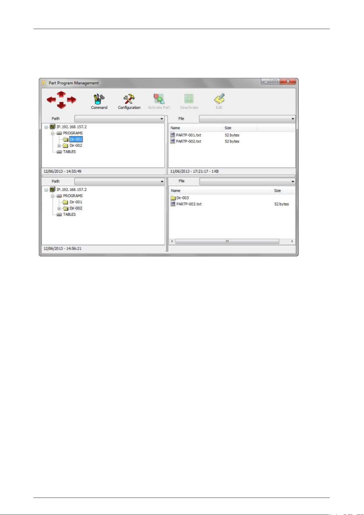
Prima Electro S.p.A. OPENcontrol – End User Manual
Four Windows Display (Quad View) 6.14
Using the “Quad View” command available in the list that appears when clicking “Command” in the
Toolbar, , you switch the display mode to the Quad View:
The two additional windows that appear have the same content of the previous windows.
For instance, the windows simplify the files drag&drop operations from a directory to another. For
example, to execute this operation select, in the upper panel, the origin directory and in the lower
panel the destination directory.
45004602H 85
Page 86
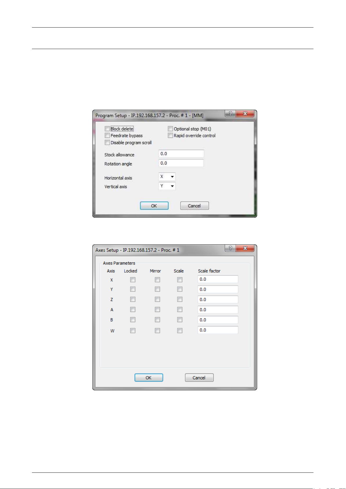
Prima Electro S.p.A. OPENcontrol – End User Manual
7. Part Program execution
Prior to executing a part program, it is possible to see a series of parameters that affect the execution
mode and enable/disable controls, visualisations and special operations.
These parameters are available in two data-entry windows, the “Program Setup” data-entry, enabled
by sending the softkey command “Setup”-“Program”
and the “Axes Setup” data-entry, enabled by sending the softkey command “Setup”-“Axes”.
For the data-entry description, refer to Ch. 3 “ User Interface”.
45004602H 86
Page 87

Prima Electro S.p.A. OPENcontrol – End User Manual
Part program execution 7.1
There are two part program execution modes:
Auto
Semi auto (block by block)
In order to execute a part program it is necessary to:
1. Select and activate the part program
2. Select the execution mode
3. Launch execution.
7.1.1 Selecting and activating a part program
These operations must be carried out before selecting the execution mode. The procedure is as follows:
Press the Part Program softkey and select the command “Activate Part Program” or “Part
Program Management”.
Select a part program for execution as described in Ch. 6.
The name of the program selected and the first lines to follow are displayed on the screen.
7.1.2 Automatic execution
This mode permits to execute all the blocks in a program without interruptions. To execute the program
in auto mode, use this procedure (for details on the operation see Ch. 3):
Select and activate the part program
Select the AUTO mode. The selection is displayed on the screen.
Press the Cycle Start pushbutton.
The selected part program will be executed from the first to the last block.
7.1.3 Block-by-block execution
This mode permits to execute one part program block (program line) at time. Usually this mode is used
to check if a new program is correct as, at the end of each program block, the execution is interrupted.
In order to execute a part program in the block-by-block mode, proceed as follow:
Select and activate the part program.
Select the “BLK/BLK” mode. The selection is displayed on the screen.
Press “Cycle Start” each time you want to execute a block. Blocks will be executed in the same
sequence in which they are programmed. After executing a block the system stops until the
operator gives another Cycle Start command.
To alter the sequence of block execution or bypass one or several blocks, use the arrow keys to position
the cursor to the desired block.
To close block-by-block execution, select another operating mode.
If BLK/BLK is pressed during the part program automatic execution, the system executes all
the blocks already analysed by the CNC and then stops. To resume part program execution
in block-by-block mode, press “Cycle Start”.
45004602H 87
Page 88

Prima Electro S.p.A. OPENcontrol – End User Manual
7.1.4 Multiblock retrace
This function permits to retrace a series of programmed blocks by moving the axes backwards along the
executed profile. Depending on the parameter configured in AMP, the number of retraceable blocks
varies from 1 through 64.
The procedure is as follows:
Press the “Cycle Stop” pushbutton to stop the axes
1. Using the “Setup” – “Multi Block Retrace” softkey command, open the “Block Retrace” data-
entry window.
2. Enable the item “Enable Block Retrace” and confirm.
3. Press the “Cycle Start” pushbutton. The axes will move backwards in the selected mode
In BLK/BLK mode the profile will be retraced one block at a time each time the “Cycle
Start” pushbutton is pressed.
In AUTO mode the system will retrace the last n blocks in the profile. n is the number of
blocks configured in AMP.
4. When the retrace move is completed the message “End of multi block retrace” appears.
In order to stop a backwards move, press “Cycle Stop” pushbutton. Now you can backwards move can be
restored or the movement direction can be inverted. In the first case, press “Cycle Start” pushbutton.
In the second case:
Using the softkey command “Setup” – “Multi Block Retrace”, open the “Block Retrace” data-
entry.
Enable “Emit Auxiliary Func.”, if during the Block Retrace execution the auxiliary functions
have to be released, stop it. If not, press “OK” and confirm.
Press the “Cycle Start” button. The axes will move in the mode selected at the previous step.
NOTE:
During part program execution in AUTO mode the “Block Retrace” function can be performed in
BLK/BLK mode. Part program execution will be resumed automatically when the profile has been
retraced and the axes have returned to their stop point.
When the “Block Retrace” function is active the axes move in point-to-point mode (G29) in the
backwords retrace, while in the forwards trace they are executed according to the programmed
modality (G27,G28,G29).
In “Block Retrace” mode, the control unit performs the motion blocks only and, on request, the
emission of auxiliary functions; assignment blocks are ignored.
The emission of auxiliary functions during the “Block Retrace” forward move can also be
enabled by assigning the MBA process variable.
MBA = 1, emission is enabled
MBA = 0, emission is disabled
When the “Block Retrace” function is active the feedrate can be altered with the Feedrate
Override function (see later in this chapter).
45004602H 88
Page 89
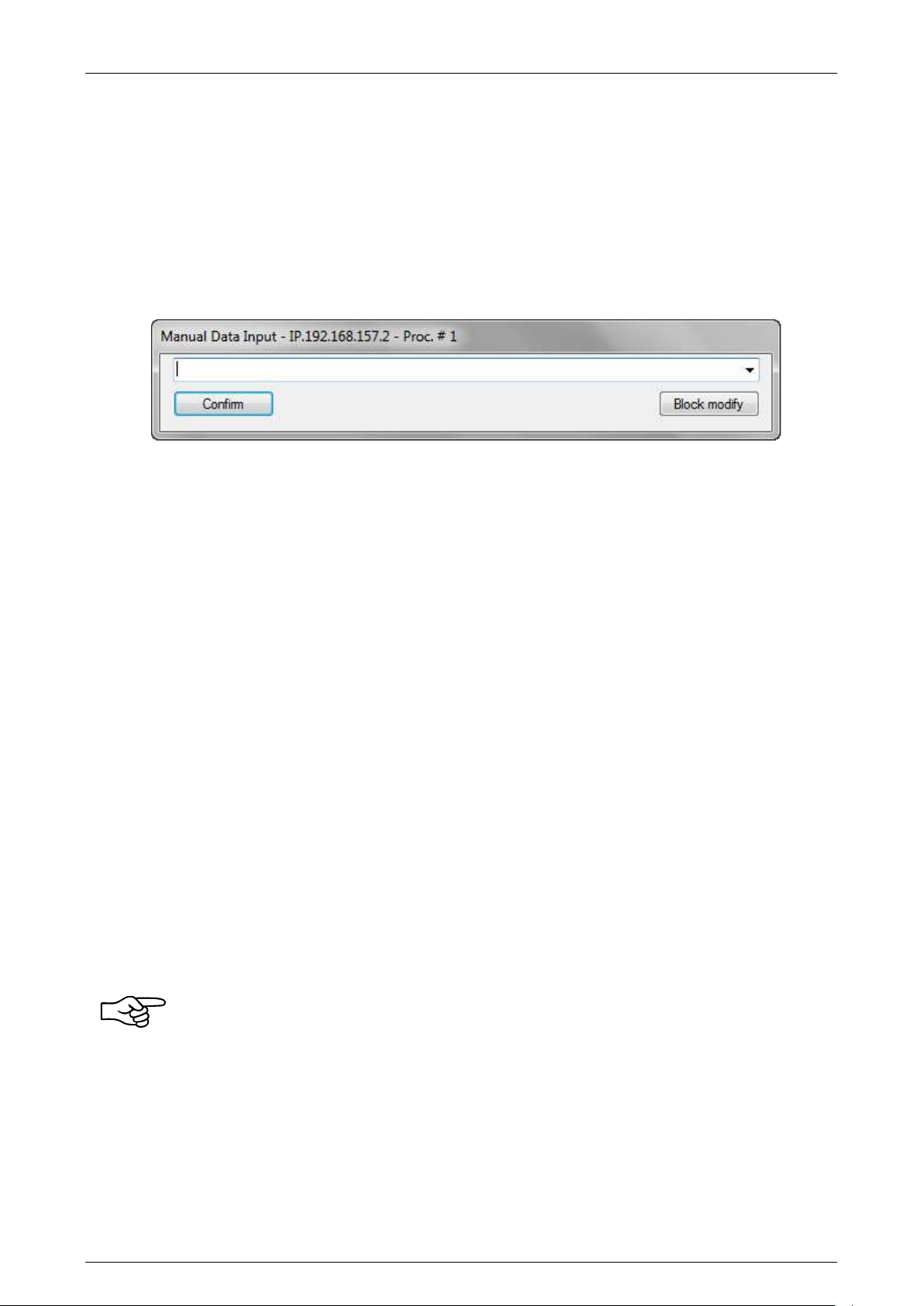
Prima Electro S.p.A. OPENcontrol – End User Manual
Executing blocks from the keyboard 7.2
The system permits to execute blocks entered from keyboard (MDI) both when a part program is active
and when no part program is selected.
7.2.1 MDI execution without an active part program
The procedure is as follow:
1. Select the MDI mode. On the screen appears an input window to write the block to execute:
2. Write the block to be executed in the data entry window
3. Press “Confirm” to confirm the input block. As the block is confirmed, the MDI line displayed in
the data entry window will turn green. The list of the last commands previously confirmed can
be displayed and reused pressing the right arrow of the input field.
4. Press “Cycle Start” to execute the inserted block.
For th introduction of another block, repeat steps 3 and 4. To reset the MDI mode, select another
operative mode.
7.2.2 MDI execution with an active part program
While the system is executing a part program it is possible to execute blocks in MDI mode. The input
block does not affect the active part program and is not retained in the system memory.
To execute a block in MDI mode use this procedure:
1. Select the MDI operative mode. This operation stops the part program execution after executing
all the pre-analysed blocks, if the program has not been stopped with the BLK/BLK softkey.
2. Write the block to be executed in the data entry window and press “Confirm” to confirm it.
3. Press “Cycle Start” to execute the confirmed block.
To input other blocks for execution repeat steps 2 and 3.
To restore part program execution select the “Automatic” operative mode or “BLK/BLK” and press the
“Cycle Start” pushbutton. The program will restart from the interruption.
If MDI is pressed during automatic execution, the system executes all the pre-analysed
blocks and then stops.
Execution of paramacros in MDI mode
This function makes it possible to run in MDI mode the paramacros called implicitly by the S,T,M,
auxiliary functions, which must have been configured beforehand as paramacros.
For information on how to program these functions as paramacros, see the Programming Manual.
45004602H 89
Page 90

Prima Electro S.p.A. OPENcontrol – End User Manual
To run a paramacro in MDI mode, proceed as follows:
1. Activate the auxiliary function in MDI mode, as described in points 1 and 2 of the previous
paragraph. This displays the name of the corresponding paramacro in the list of active programs.
2. Deactivate the MDI mode by pressing the MDI softkey again.
3. Press the [CYCLE START] button to execute the paramacro.
At the end of the execution, the paramacro is closed and the system returns to MDI mode.
NOTE:
If you try to activate the same paramacro several times, the error message “programme already
selected” (error 149) appears.
7.2.3 Executing part of a part program
The partial execution of a part program is the execution of the instructions between two defined blocks.
When part program blocks are numbered the system can execute the part of program delimited by two
block numbers.
The procedure is as follows:
1. Select and activate the part program.
2. Open the data-entry using the “Part Program” – “Exec From To” softkey command
3. Insert the starting block number, the label or the number of the file line where starting the
execution
4. Select and fill in the fields (block number, label, number of the file line or $BRK instruction) of
the conditions determining program stop execution.
5. Press “OK” to confirm data
6. Press “Cycle Start” to start executing the part of the program delimited by the specified blocks.
Modifying blocks in BLK/BLK mode 7.3
Part program blocks can be altered and executed from the keyboard. These alterations do not affect the
original programmed block and are not saved in the active program.
To modify a programmed block use this procedure:
1. Select the BLK/BLK operative mode
2. Execute the program up to the block to be edited.
3. Select the MDI mode.
4. In the input window, press the “Modify” pushbutton to move the program block on the data
entry window.
5. Edit the block displayed in the data entry window and press “Enter” to confirm the
modifications.
6. To execute the modified block press “Cycle Start”.
7. To quit the Block Modify select an operative mode different from MDI.
NOTE:
This procedure is not applicable when tool offset is active (G41, G42).
45004602H 90
Page 91

Prima Electro S.p.A. OPENcontrol – End User Manual
Strings search 7.4
The following procedure permits to search for a string of characters in an active program.
1. Open the data-entry “Text Search” using the “Part Program” – “String Search” softkey
command
2. Insert in the input field the text to search
3. Press the “UP” button to start the search backwards. Press the “DOWN” button to start the
search
When the search is completed, if one block contains the text required, it is displayed backwards on the
screen. If the string is not found after searching in a given direction, one of the following error messages
appears: "End of File" or "Beginning of File".
Feedrate Override 7.5
The feedrate value to be used in the program is specified by the F value parameter. To alter this value
without modifying the program use this procedure:
1. Use the mouse to activate on the screen the button to select the overrides and select FRO (Feed
Rate Override).
2. Using the buttons “+” and “-“ on the right, increase or decrease the present override value.
Each time one of the two button is pressed, the override percentage has a 1,25%
increase/decrease. The allowed override has a range from 0% to 125% of the value configured,
unless it has been programmed the maximum feed configures. In this case, the override has a
range from 0% to 100%.
Example:
If the programmed feedrate value is 2000 MMPM (mm per minute) and a 50% variation is applied, the
actual feedrate will be 1000 MMPM.
Spindle feedrate override 7.6
The procedure to change the spindle feedrate, programmed in the part program in execution with the “S
value” operator is:
1. Use the mouse to activate on the screen the button to select the overrides and select SRO
(Spindle Speed Override).
2. Using the buttons “+” and “-“ on the right, increase or decrease the present override value.
Each time one of the two button is pressed, the override percentage has a 1,25%
increase/decrease. The spindle override percentage has a range from 50% to 150% of the
programmed value.
Example:
If the programmed spindle feedrate is 1500 RPM (round per minute) and you select a 50% override, the
real spindle feedrate will be 750 RPM.
45004602H 91
Page 92

Prima Electro S.p.A. OPENcontrol – End User Manual
Rapid Feedrate Override 7.7
The procedure to change the rapid feedrate configured in AMP is:
1. Use the mouse to activate on the screen the button to select the overrides and select RAP (RAPid
override).
2. Using the buttons “+” and “-“ on the right, increase or decrease the present override value.
Each time one of the two button is pressed, the override percentage has a 1,25%
increase/decrease. The rapid feedrate override has a range from 0% to 125% of the programmed
value.
Example:
If the programmed rapid feedrate is 1500 3000 MMPM (millimetres per minute) and you select a 50%
override, the real spindle feedrate will be 1500 MMPM.
Execution in Dry Run mode 7.8
In Dry Run mode, it is possible to try to execute a part program without any command being sent to the
drives of the axes or to the machine logic (I/O inhibited). This feature is activated by pressing the
“Setup” softkey and then “Dry Run”.
With Dry Run active, it is also possible to verify program correctness graphically by way of the WinNBI
Machine Plot utility.
For further details about use of Machine Plot, see Ch.11.
When “Dry Run” is active, the block reading speed is inversely proportional to the values selected for
FRO and RAP.
The higher is the percentage, the slower is the block read rate. Maximum block read rate is equivalent
to 0%.
Memory Search 7.9
Memory searching means searching for the interruption block and subsequently resume the interrupted
cycle automatically or searching for a pre-set block where to start machining. The parameters which
identify univocal an executing cycle are stored and continuously updated during the execution of the
program. According to these parameters it is possible to carry out an automatic searching.
Memory searching can be accomplished in two ways:
Automatic memory search for the interruption block (due to switch-off or reset of the
machine)
Memory search for a pre-set block.
45004602H 92
Page 93

Prima Electro S.p.A. OPENcontrol – End User Manual
7.9.1 Automatic Search
To search automatically for the block which interrupted the part program, proceed as follows:
1. Select the part program in which machining was interrupted.
2. Set “Automatic” operative mode
3. Select the “Setup” softkey and then “Search in memory”: the system starts searching. The
screen displays the reverse MemS flag.
4. Press “Cycle Start”: the system runs the searching and in the end the message NC156 end of
search in memory and the programmed dimensions of the axes position for the cycle reset are
displayed. The block of the part program which will be executed at the end of the search, when
the program is restarted, is displayed on reverse image. By switching to BLK/BLK and pressing
“Cycle Start”, the search can be continued to the desired block.
5. Select again the softkey “Setup” and then “Search in memory” to exit the status of the stored
search.
The system is now ready to restart the working cycle.
7.9.2 Search for a pre-set block
To search for a Nxxxx block of a part program proceed as follows:
1. Select the part program
2. Set automatic mode
3. Select the “Setup” softkey and then “Search in memory”: the system starts searching. The
screen displays the reverse MemS flag.
4. Select the “Part Program” softkey and then “Exec From To”, set the starting and the finishing
blocks for the memory searching in the data entry. The starting block can also be omitted (by
default part program starts with the first block); the finishing block stands for the previous
block from which you want to restart the cycle. The searching blocks cannot be included in a
subprogram
5. Press “Cycle Start”: the system runs the searching and in the end the message NC 156 End of
search in memory and the programmed dimensions for the position of the cycle reset are
displayed. The block of the part program which will be executed at the end of the search, when
the program is restarted, is displayed on reverse image. By switching to BLK/BLK and pressing
“Cycle Start”, the search can be continued to the desired block.
6. Select again the “Setup” softkey and then “Search in memory” to exit the search memory
status. on the scree the flag MemS turns off.
Before exiting the search status, it is possible to continue the searching up to another block resetting
the number by means of the “Exec From To” softkey and pressing “Cycle Start” again.
45004602H 93
Page 94

Prima Electro S.p.A. OPENcontrol – End User Manual
Restart a working cycle 7.10
After exiting the MEMORY SEARCH mode to restart the working cycle, proceed as follows:
1. Press “Cycle Start”: the system send auxiliary functions to the machine logic and enters HOLD
status. Auxiliary functions are sent also in SEARCHING mode provided that the logic has been
adequately pre-set.
2. Position axes on the programmed dimensions reversing on the profile (JOG RETURN softkey,
MANUAL mode).
3. Select again automatic or semiautomatic mode.
4. Press the button “Cycle Stop” to exit from HOLD status.
5. Press “Cycle Start “to restore the working cycle.
Searching Mode 7.11
When using multiprocess systems, memory searching can be accomplished on the first 4
processes only.
When an interrupted cycle is restored automatically, the program is restarted from the
beginning of the block where the interruption took place. When a cycle is restored from a preset block, it is restarted from the block next to the one searched.
Automatically resuming the search, if the position of the start of the search is changed, for
example, switching to BLK/BLK and using the arrow keys or setting the starting block only in the
data entry “Exec From To”, the search starts from the new position and ends when the system
has executed the number of blocks stored throughout the machining phase.
The same thing happens when a search is carried out for a set block if the end block is not
specified.
Automatic searching is only possible provided the relevant configuration (AMP) is enabled. It can
only be used when machining is executed at the beginning of the part program. Similarly, if
during a working cycle MDI-blocks are executed, memory searching subsequently run on that part
program would not work.
When machine is switched off, modified data-entry from “Program Set Up” or from other data
entries are erased.
When searching, variable allocation blocks are always executed.
Searching is not operating properly when part program makes use of variables written or read
from logic or from other environment.
Following are listed the strings that can and cannot be used within a part program in order to
execute a memory searching:
The following strings are accepted in searching mode:
DAN, IPB, UAO, UTO, UIO, SOL, DPA, PAE, PAD, MIR, ROT, SCF, AXO, LOA, RPT, ERP, CLS, PTH,
EPP, EPB, GTO, IF, ELSE, ENDIF, GDV, RDV, UGS, CGS, DGS, DIS, DSB, GTA, ECM, PRO, PVS, GTP,
CCP, SPA, SPF, SPP, CLP, TGL, OPN, WRT, REA, CLO, DEL, INS, PRO, RTP, ROP, GPS, PLS.
45004602H 94
Page 95

Prima Electro S.p.A. OPENcontrol – End User Manual
The following string is accepted but non-executed in searching mode:
DLY.
The following strings are not accepted in searching mode:
RQO, RQT, RQP, TOU, DPP, UDA, SDA, UPR, UVP, UVC, TCP, REL, WOS, SND, WAI, EXE, DCC, FIL,
SOP, GET, PUT, SCL, EPS, CON, COF, HON, HOF, RES, SMD, SAX, DIR, JOG, FHO, UVA,
Besides the following tracing cycles are not accepted: G72, G73, G74.
Block reading speed is inversely proportional to the values selected for FRO and RAP. The 0%
corresponds to the maximum block reading feed.
45004602H 95
Page 96
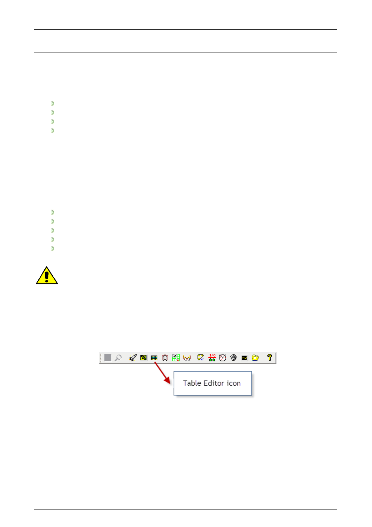
Prima Electro S.p.A. OPENcontrol – End User Manual
8. Using Tables
The system manages several groups of parameters which, if they were not structured in an organised
way, would be difficult to manage. These parameters have been arranged into a number of tables.
These tables are:
Origins
Tools
Tool Offsets
User
In the CNC OPENcontrol system, the tables are stored in a dual port memory, accessible directly from
the machine logic (WinPLUS) or by the ISO user program. The tables are saved even after the system has
been turned off.
Each of these tables is described later in this chapter. The tables are managed by the Table Editor,
allowing both the tables stored in the dual port memory and the tables stored on the hard disk to be
changed. Here are some of the editing operations available with the Table Editor:
Table uploading, opening and saving
Modification of table data
Incremental modifications to table fields
Measure unit conversion (mm/inch)
Backup and restore of the tables or all of the CNC memory
This manual describes the standard table configuration. The table structure can be modified by
the OEM (amount of data, name and position of the fields) and can then appear to the end user
in a manner different from the standard: in that case the OEM should describe the table
functions.
Enabling Table Editor 8.1
To enable the Table Editor, just press the button in the icons bar
or select UTILITY and then TABLE EDITOR from the Tool Bar. At this point you will see the following
window.
45004602H 96
Page 97
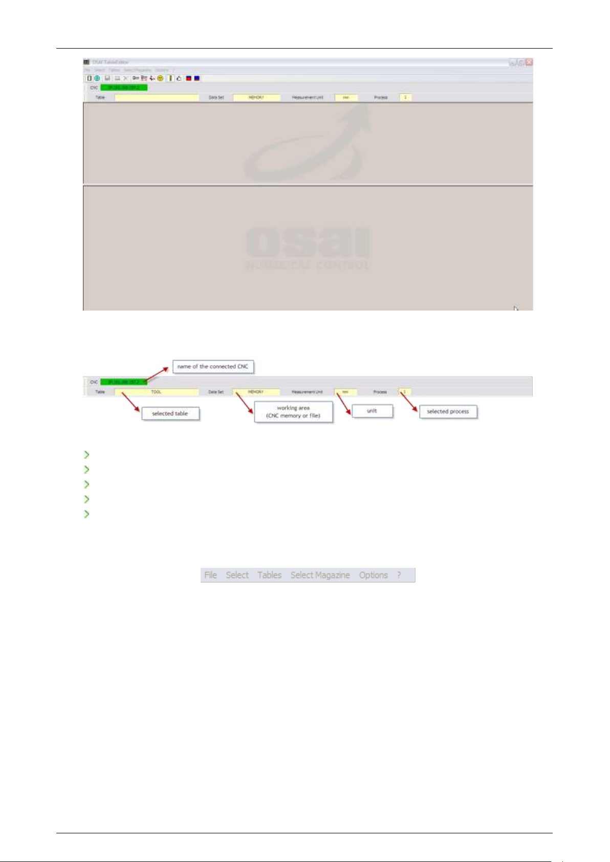
Prima Electro S.p.A. OPENcontrol – End User Manual
The upper section displays the following information:
name of the connected CNC
selected table (TOOL, OFFSET, ORIGIN, USER)
working area (CNC memory or file on PC)
unit of measurement (mm or inch)
selected process
The following commands are available in the upper bar:
45004602H 97
Page 98

Prima Electro S.p.A. OPENcontrol – End User Manual
FILE
Table Builder
This command allows you to access the Table Builder that is
described in the next chapter. This ambient is reserved for
the OEM, therefore it is password protected. Using this tool,
the tables can be customised, i.e. configuring which tables
and fields are displayed to the end user. It also configuration
of up to 16 customised tables, where each field has a custom
label. Finally, the graphical representation, i.e. the field
positions can be customised, the text alignment, the
dependence of the selected measurement units, etc.
Save
This command is only available when working on files. It
allows the changes made to the data in the file to be saved
to the file.
Save As
After making changes to a file, using this command the
changes can be saved to a file with a different name. If
working with the CNC memory, by using this command the
data can be saved from the CNC memory to a file.
Update Memory
With this command data can be copied from a file to the
corresponding table in the CNC memory: this is the reverse
command to “Save As”.
Backup Memory
This command allows the entire area data of the tables
(tool, offset, origin, user) to be saved from the CNC memory
to a single file.
Restore
Memory
This command allows all the data relating to the data area
(tool, offset, origin, and user) to be copied from a file to the
memory of the CNC. This is the reverse command to “Backup
Memory”
Work on
Memory
Allows the memory of the selected CNC to be modified. This
is possible only with a connected CNC. Any change made is
immediately active on the CNC and will affect its operation.
Work on File
Allows a file to be modified, therefore the changes made do
not affect the CNC functioning. With this tool it is possible
to prepare data files relating to the tools and to the origin
without being connected to a CNC.
Print
Command unavailable.
Exit
Exit from Table Editor.
45004602H 98
Page 99
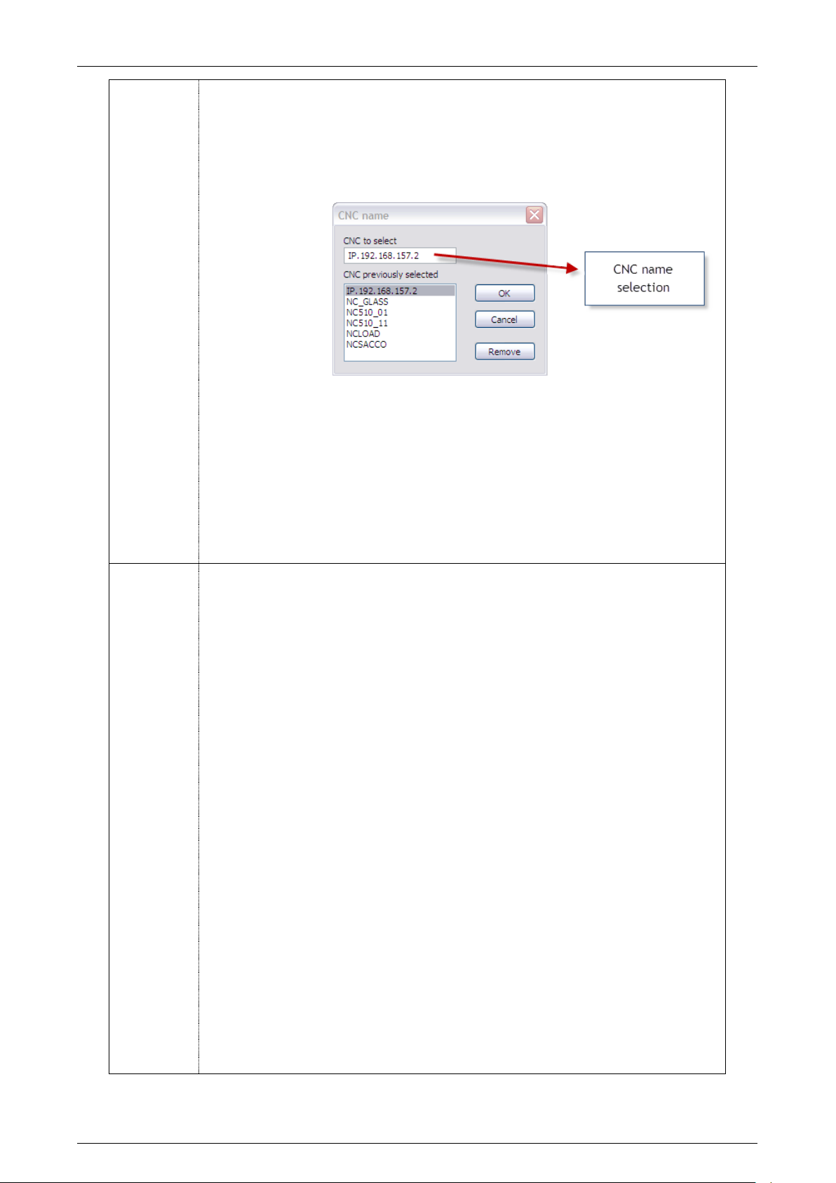
Prima Electro S.p.A. OPENcontrol – End User Manual
SELECT
CNC
This command defines the CNC name with which the Table
Editor will communicate. This setting is stored when the
Table Editor is exited and the connection with the selected
CNC is automatically restored following the next reboot of
the Table Editor.
Process
This command defines the process number with which the
Table Editor is associated.
This is effective only when the Table origins change:
because, the Tool, Offset and User tables apply to all
processes while the Origins are specific to each process.
Project
This command allows a “project” created with the Table
Builder to be opened and changed and saved. Therefore, this
is a command reserved for the OEM.
TABLES
Tool
If the “Work on Memory” mode is selected, this command
allows the tools table to be changed directly in the CNC
working memory.
If the “Work on File” mode is selected, the name of the tools
data file to be edited is required.
Offset
If the “Work on Memory” mode is selected, this command
allows the tool offset tables to be changed directly in the
CNC working memory.
If the “Work on File” mode is selected, the name of the tool
offsets data file to be edited is required.
Origin
If the “Work on Memory” mode is selected, this command
allows the origins tables to be changed directly in the CNC
working memory. It should be noted that the origins are
specific to each process.
If the “Work on File” mode is selected, the name of the
origins data file to be edited is required.
User
If the “Work on Memory” mode is selected, this command
allows the user tables to be changed directly in the CNC
working memory.
If the “Work on File” file, the name of the user data file to
be edited is required.
45004602H 99
Page 100
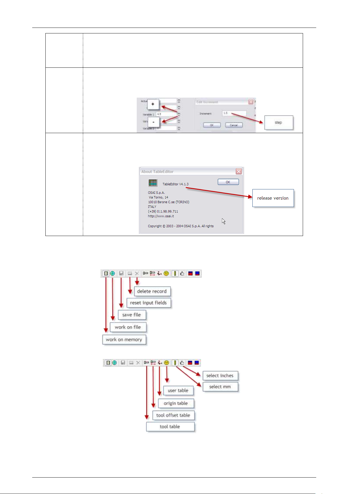
Prima Electro S.p.A. OPENcontrol – End User Manual
SELECT
MAGAZINE
All
1..10
Selects the magazine to which the Tools Table applies
(optional).
Unavailable command.
OPTION
Edit Increment
This command allows definition of a value that will be added
or subtracted from the value of the selected field in the
table for each press of the button
?
Help
Enables the Table Editor on-line help
About Table
Editor
Using this command displays the Table Editor release
version.
Some of the commands described above can be accessed directly from the Tool Bar, as outlined in the
following figures:
45004602H 100
 Loading...