

Page 1
说明书
客户名称
产品型号
业务经理
设计时间
版次
印刷说明:
1.此印刷品专用号
英国 PRIMA
DF90E
薛孝田
2017.05.31
01
Cod:0103084742
设计
会签
型号经理
会签
电气工程师
审核
批准
工业设计工程师负责根据客户要求对版面进行设计修改;
型号经理负责会签确定机器尺寸/外观型号/具体参数等;
电气工程师负责会签确定电压/功率/接线图/认证标志等;
销售经理负责审核确定客户对文件是否确认;
技术部长负责批准确定文件是否下发;
2.此印刷品自下发之日起开始实施。
3.此印刷品最终成品大小为A4纸一半大小。
4.此印刷品黑白印刷。
5.此印刷品要求字迹清晰、不能有漏印、错印、模糊现象。
于丽
Page 2
PRDE0004
Downdraft Cooker Hood
Cod:0103084742
Page 3
IMPORTANT INFORMATION FOR THE CORRECT DISPOSAL OF THE PRODUCT, IN ACCORDANCE WITH EC
DIRECTIVE 2002/96/EC.
Page 4
Using your Extractor
For best performance, you should switch on the extractor 15 minutes before starting for approximately 15 minutes
after the end of cooking.
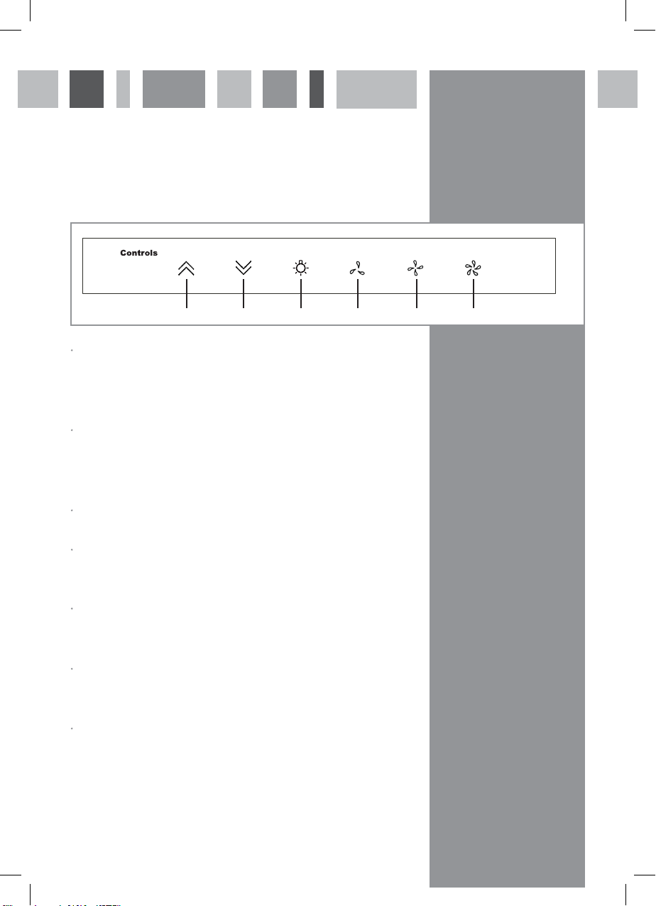
Control Panel
Fig. 1
Up key: Press for 2 seconds, the section of the extractor rises. When moving, touch the key, it will stop.
Press again 2 seconds, the section continues to rise. If you press the Down key for 2 seconds, the section
will drop down. When the section rises halfway, the fan will start working at low speed.
Down key: Press for 2 seconds, the section drops down. When moving, touch key and it will stop,
Press again 2 seconds, it will continue to drop down to the bottom. Press the Up key again to make the section
rise. When the section drops down halfway, the fan will stop.
Light key: Touch the key to switch on/o the lights. When the section drops down halfway, the light will turn o.
High speed key: Touch the key for high speed; touch again to switch o the fan, If you press the medium speed
key or low speed key, the fan speed will change.
Medium speed key: Touch the key for medium speed; touch again to switch o the fan. If you touch the high
speed key or low speed key, the fan speed will change.
Low speed key: Touch the key for low speed; touch again to switch o the fan. If you touch the high speed
key or middle speed key, the fan speed will change.
Up key Down key Light Key Low speed key Medium speed key High speed key
Timer: Press any speed button for 3 seconds when the appliance is working and the key will flash.
It will show timer mode for 15 minutes and will stop working after 15 minutes.
3
Page 5
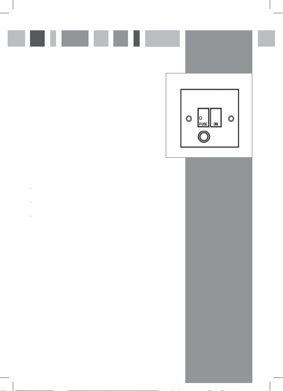
Mains Electricity Connection
THIS APPLIANCE MUST BE CONNECTED TO THE MAINS SUPPLY BY
A COMPETENT PERSON, USING FIXED WIRING VIA A DOUBLE POLE
SWITCHED FUSE SPUR OUTLET AND PROTECTED BY A 3A FUSE.
Warning! This appliance must be earthed.
We recommend that the appliance is connected by a qualified
electrician, who is a member of the N.I.C.E.I.C. and who will comply with
the I.E.T. and local regulations.
The wires in the mains lead of this appliance are coloured in
accordance with the following code:
Green & Yellow = Earth, Blue = Neutral, Brown = Live.
As the colours of the wires in the mains lead for the appliance may
not correspond with the coloured markings identifying the terminals
connecting to the fuse spur, proceed as follows:
The wire which is coloured green and yellow must be connected to
the terminal marked E (Earth) or coloured green.
The wire which is coloured blue must be connected to the terminal
marked N (Neutral) or coloured black.
The wire which is coloured brown must be connected to the
terminal marked L (Live) or coloured red.
Note: Use a 3A Fuse
DOUBLE POLE SWITCHED
FUSE SPUR OUTLET
USE A 3 AMP FUSE
Assembly and electrical connection should be carried out by
specialised personnel.
When installing this product we recommend you seek the help of
another individual.
Do not mount the isolation switch behind the chimney section. It is
a requirement that you must be able to isolate the extractor from the
mains electrical supply after installation.
This appliance is intended to be connected to the mains electrical
supply by means of an isolation switch and fused spur and is intended
to be protected by a 3A fuse. The use of a 13A fuse can cause damage
to the internal wiring in the event of a fault, and may also invalidate the
warranty.
4
Page 6
164W
if registered within 30 days of purchase.
5
Page 7
Screw
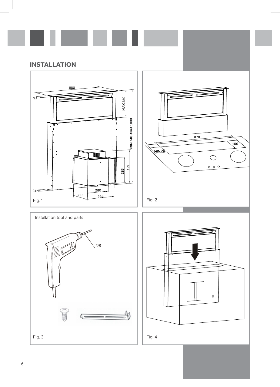
Cut Out Dimensions.Extractor Dimensions.
Insert extractor into cavity.
Screw
Bracket
Page 8
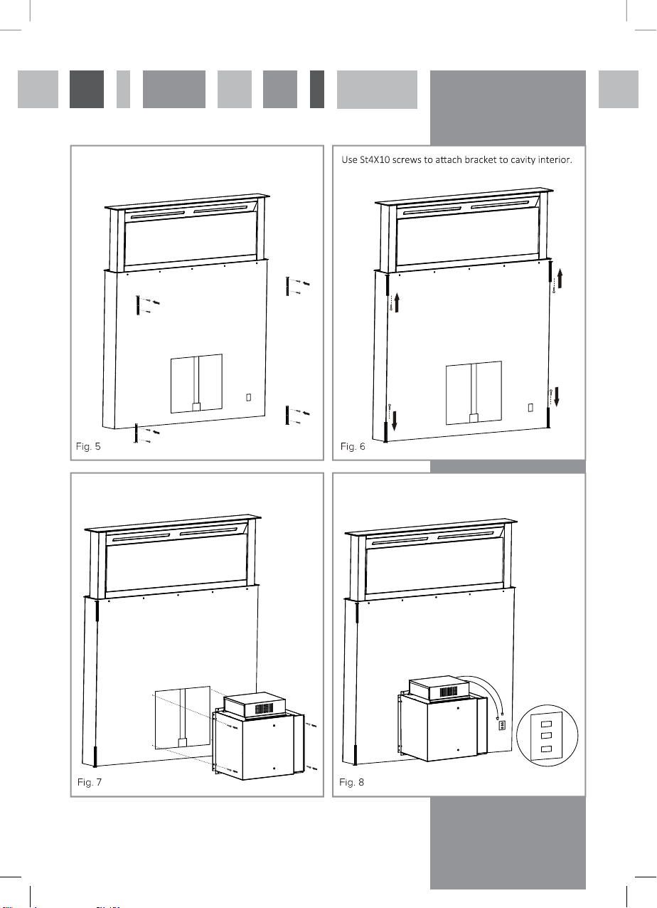
Install in place, then use s14x10 screws to fix bracket
to the extractor
Use ST4x10 screw fix motor on the extractor. Install power cable as shown below.
.
7
Page 9

Installation Instructions
BEFORE YOU BEGIN
Read these instructions completely and carefully.
CAUTION:
Due to the weight and size of this cooker hood and to reduce the risk of personal
injury or damage to the product, TWO PEOPLE ARE REQUIRED FOR PROPER
INSTALLATION.
Note to Installer: Please leave these instructions with the customer.
Note to Customer: Keep these instructions in a safe place for future reference.
Installation of this appliance requires basic mechanical and electrical skills and
should preferably be undertaken by a professional electrician.
Proper installation is the responsibility of the installer.
WARNING:
To reduce the risk of the fire or electrical shock, do not use this cooker hood with
any external speed control device. Any such alteration from original factory wiring
could result in damage to the unit and/or create an electrical safety hazard and
will invalidate the warranty.
Installation Guide
Refer to Figure Fig.1 open mounting holes on the cooker:
If you want to install the hood decorative panels flush with the worktop, see (Fig.2)
diagram to open and align the mounting holes.
When mounting the hood into the cooker openings, handle with care to avoid
damage to decorative parts. See (Fig.4).
The hood decoration panel and cooker should be flush with the mounting foot
fixed, If the cooker is tiled, the top two mounting feet cannot be installed correctly.
See (Fig.5, Fig.6)
8
Page 10
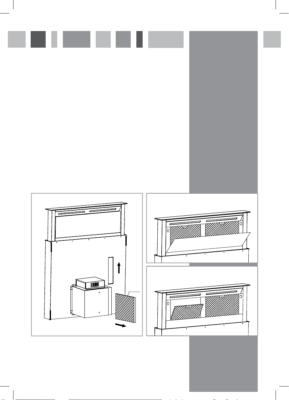
Replacement of Charcoal Filter
Remove the fixed plate for the charcoal filter, then you can install the filter.
See (Fig.9) The activated charcoal filter provides air purification. After every
4 months, it is advisable to replace this filter. Cleaning or replacement of the
activated charcoal filter, depending on the frequency of use, is strongly
recommended.
Cleaning Grease Filter
1. Pull the glass gently, release the lock and the glass will rise up.
2. Press and hold the filter handle and pull it forward, remove filter from the filter
holes, then remove the filter.
The installation process can be reversed to reinsert the filter. (Fig.10/11).
3. To prevent fire, it is recommended that every two months you clean the filter
according to the following:
- Remove filter from the hood and soak in a cleaning solution.
- Rinse thoroughly with warm water to clean and dry.
- The filter can also be cleaned in the dishwasher.
4. The aluminium panel may become discoloured after repeated
washing. This is normal and there is no need to request a replacement
filter.
Open flap.Lift flap and remove charcoal filter.
Fig. 9
carbon
filter
Fig. 10
Remove filter for cleaning.
Fig. 11
9
Page 11
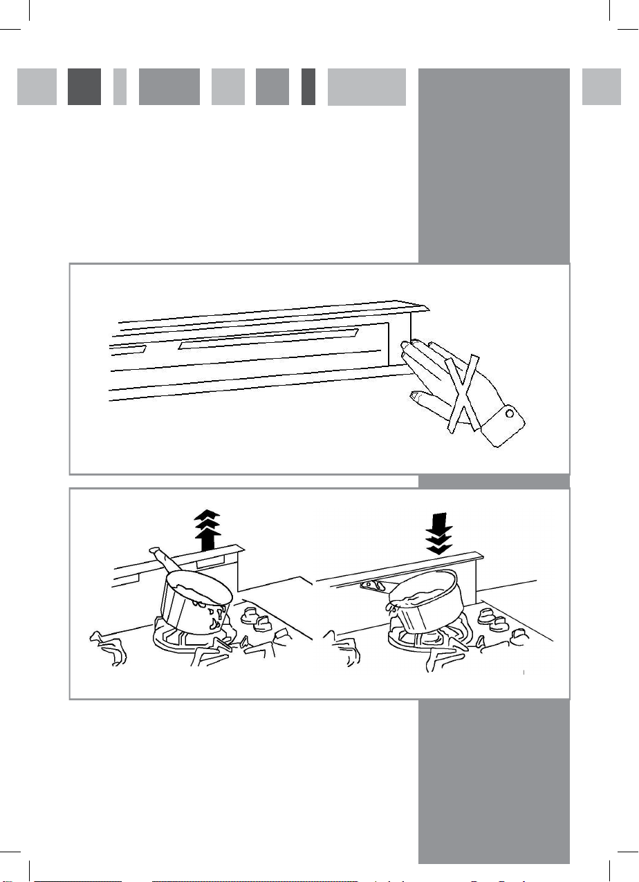
Danger
1. When the panel is lowering, DO NOT place your hand on the decorative panel
– DANGER of trapping fingers. See (Fig.12) below.
2. Ensure that there are no other items in the vicinity to hinder the hood from rising
or lowering, eg. handles, spoons, pens, etc. See (Fig.13).
3. KEEP CHILDREN AWAY FROM THE APPLIANCE WHEN IT IS OPERATING.
4. Do not leave pan handles over area where hood rises, due to risk of spillage.
Fig. 12
Fig. 13
10
Page 12
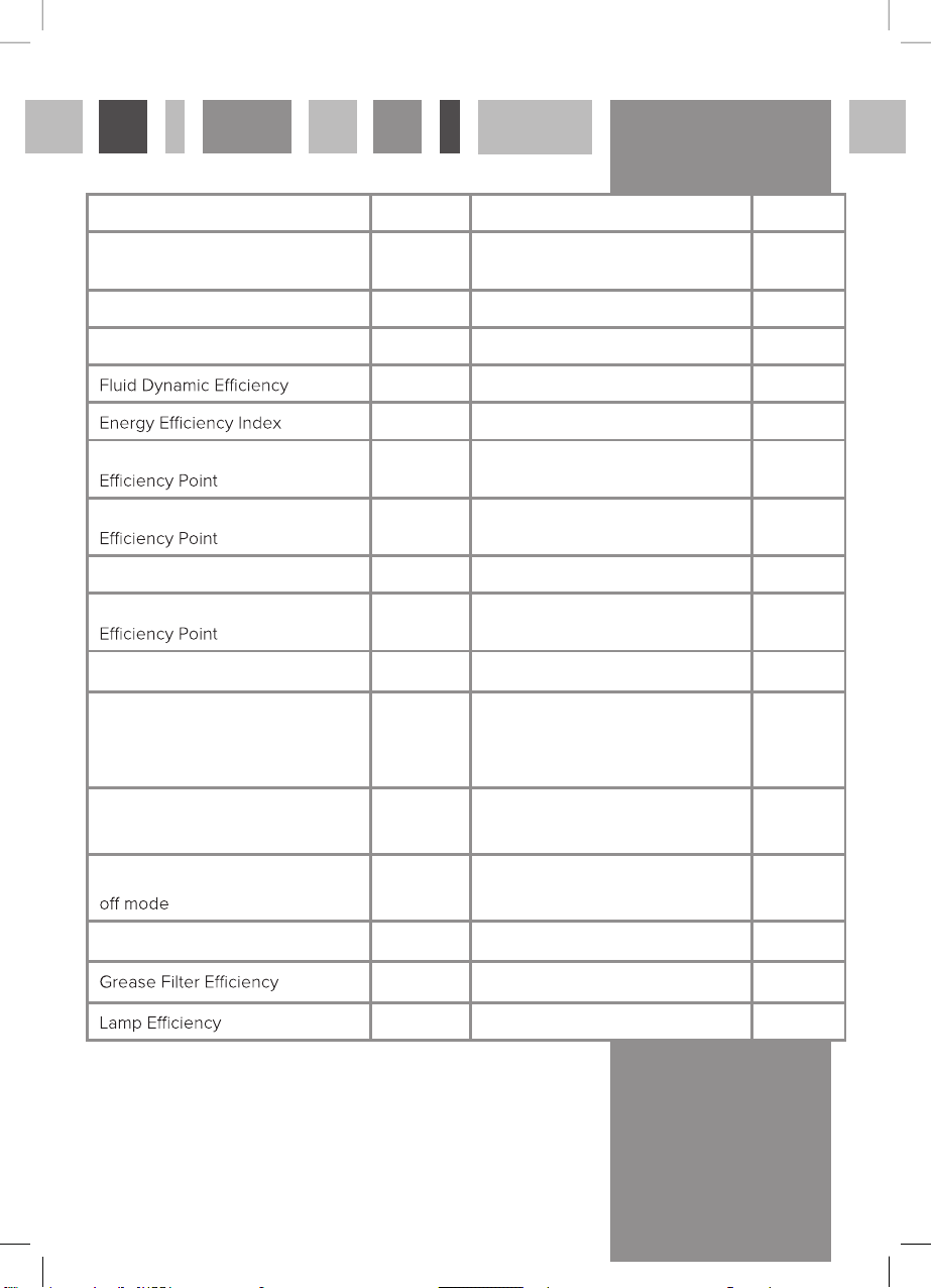
Attribute Symbol Value Units
Model Identification
Annual Energy Consumption AEC
Hood
PRDE0004
97.9 kWh
Time Increase factor f 1.7
Measured Airflow at Best
Measured Pressure at Best
Maximum Airflow Q
Measured Electric Power at Best
FDE
EEI
Q
BEP
P
BEP
MAX
W
BEP
Hood
Hood
9.4
96.3
266.7 m3/h
194 Pa
510 m3/h
153.1 W
Nominal Lighting Power WL 4 W
Average Illumination of the
E
Middle
350 Lux
lighting system on the cooking
surface
Measured Power Consumption in
P
S
0.7 W
standby
Measured Power Consumption
Noise Level
E & O E. All instructions, dimensions and illustrations are provided for guidance only. PRIMA reserves
the right to change specifications without prior notice.
P
O
L
WA
GFE
LE
Hood
Hood
0.47 W
69 dBA
67.6 (D) %
87.5 (A) %
11
Page 13
Please call PRIMA CARE for Service;
Contact number: 0344 576 6841
Website: www.prima-appliances.uk/primacare
12
 Loading...