

Page 1
Specification 1
Test program 36-39
Theory of parts 19-33
Contents
Function Description 4-18
Inspection 40-43
Location 19
PCB 19-21
Inlet valve 22-24
Drain pump 25-26
Heater 27-28
Washing pump 29-30
Procedure 37
Error code 38-39
Water circuit 4-5
Circuit schematic 6
Exploded View & Part List 7-18
Technical Service Manual
D
i
s
h
w
a
s
h
e
r
Pressure switch 31
NTC 32-33
SAFETY NOTICE
This documentation is only intended for qualified technicians who are
aware of the respective safety regulations.
Model
LPR661
LPR659
Operation instructions 2
Installation instructions 3
Flowmeter 34-35
Page 2
Specifications
Models:
220-240V, 50Hz
0.04MPa-1.0MPa
below 60℃
12
Models:
220-240V, 50Hz
0.04MPa-1.0MPa
below 60℃
8
Supply water pressure
Supply water temperature
Settings
LPR661
Electrical supply
Supply water pressure
Supply water temperature
Settings
LPR659
Electrical supply
1
Page 3
Operation instructions
2
Control Panel
5
Half washing button:To select half washing.
(Optional half washing means that the lower spray arm
does not run, so you should load the upper basket only).
Power on light: To come on when Power ON/OFF
button is pressed down.
11
2
3
4
ON/OFF Button: Will turn on/off the power supply.
6
Program button: To select washing program
when the button is pressed.
Delayed Start Button: Press this button to set the
delayed hours for washing. You can delay the start
of washing up to 24 hours. One press on this
button delays the start of washing by one hour.
11
2
3
4
5
6
Display Window: delay time, running indicator,
fault codes etc.
On
Off
P
rog.
Delay
Di617
1
2
/
/
NOTE:
Turning on the Appliance
Starting a wash cycle...
Draw out the lower and upper basket, load the dishes and
push them back. It is commended that loading the lower
basket first, than the upper one (see the section entitled
“Loading the Dishwasher”).
Pour in the detergent (see the section entitled “Salt,
Detergent and Rinse Aid”).
Insert the plug into the socket. The power supply is 220-240
VAC 50 HZ, the specification of the socket is 10 A 250 VAC.
Make sure that the water supply is turned on to full pressure.
Open the door,press the ON/OFF button,and the ON/OFF light
will turn on.
Pre
ss the "prog. "button to select a desired "Wash cycle".(see
the section entitled."Wash Cycle Table".)
With a little force to ensure the door is properly closed.
NOTE: A click will be heard when the door is closed perfectly.
When the washing is over, you can shut off the switch by
pressing ON/OFF button.
Change the Programme . . .
Premise: A cycle that is underway can only be modified if it
has only been running for a short time. Otherwise, the detergent
may have already been released, and the appliance may have
already drained the wash water. If this is the case, the detergent
dispenser must be refilled (see the section entitled " Loading the
Detergent " ).
Open the door,Press current prog. button more than three
seconds to cancel the program ,then you can change the
program to the desired cycle setting (see the section entitled
" Starting a wash cycle. . . " ). Then, close the door.
NOTE: If you open the door when washing, the machine
will pause. When you close the door , the machine will
resume working after 10 seconds.
1
2
3
4
5
6
If all the lights begin to glimmer, this indicates the machine has developed a fault,
please turn off the main power and water supply before calling a service agent.
Page 4
2
I
nstallation instructions
3
Page 5
w
a
s
h
i
n
g
p
u
m
p
w
a
s
h
i
n
g
p
u
m
p
pr
essure
switch
p
r
e
s
s
u
r
e
s
w
i
t
c
h
dr
ain
pu
m
b
d
r
a
i
n
p
u
m
b
dr
ain
ho
s
e
d
r
a
i
n
h
o
s
e
ov
er
flow
switch
o
v
e
r
f
l
o
w
s
w
i
t
c
h
ai
r
breaker
a
i
r
b
r
e
a
k
e
r
in
let
valve
i
n
l
e
t
v
a
l
v
e
in
let
ho
s
e
i
n
l
e
t
h
o
s
e
Regeneration
water
route
R
e
g
e
n
e
r
a
t
i
o
n
w
a
t
e
r
r
o
u
t
e
u
p
p
e
r
s
p
r
a
y
a
r
m
u
p
p
e
r
s
p
r
a
y
a
r
m
t
o
p
s
p
r
a
y
t
o
p
s
p
r
a
y
t
u
b
e
t
u
b
e
Inlet
water
r
o
u
te
I
n
l
e
t
w
a
t
e
r
r
o
u
t
e
up
per
spray
a
r
m
u
p
p
e
r
s
p
r
a
y
a
r
m
so
ftener
s
o
f
t
e
n
e
r
W
a
t
e
r c
i
r
c
u
i
t s
c
h
e
m
e
regeneration valver
e
g
e
n
e
r
a
t
i
o
n
v
a
l
v
e
Cycle
water
r
o
u
te
C
y
c
l
e
w
a
t
e
r
r
o
u
t
e
Drain
water
r
o
u
te
D
r
a
i
n
w
a
t
e
r
r
o
u
t
e
Water Circuit Function Description->
4
F
o
r
a
l
l
t
h
e
m
o
d
e
l
s t
h
i
s m
a
n
u
a
l m
e
n
t
i
o
n
e
d
Page 6

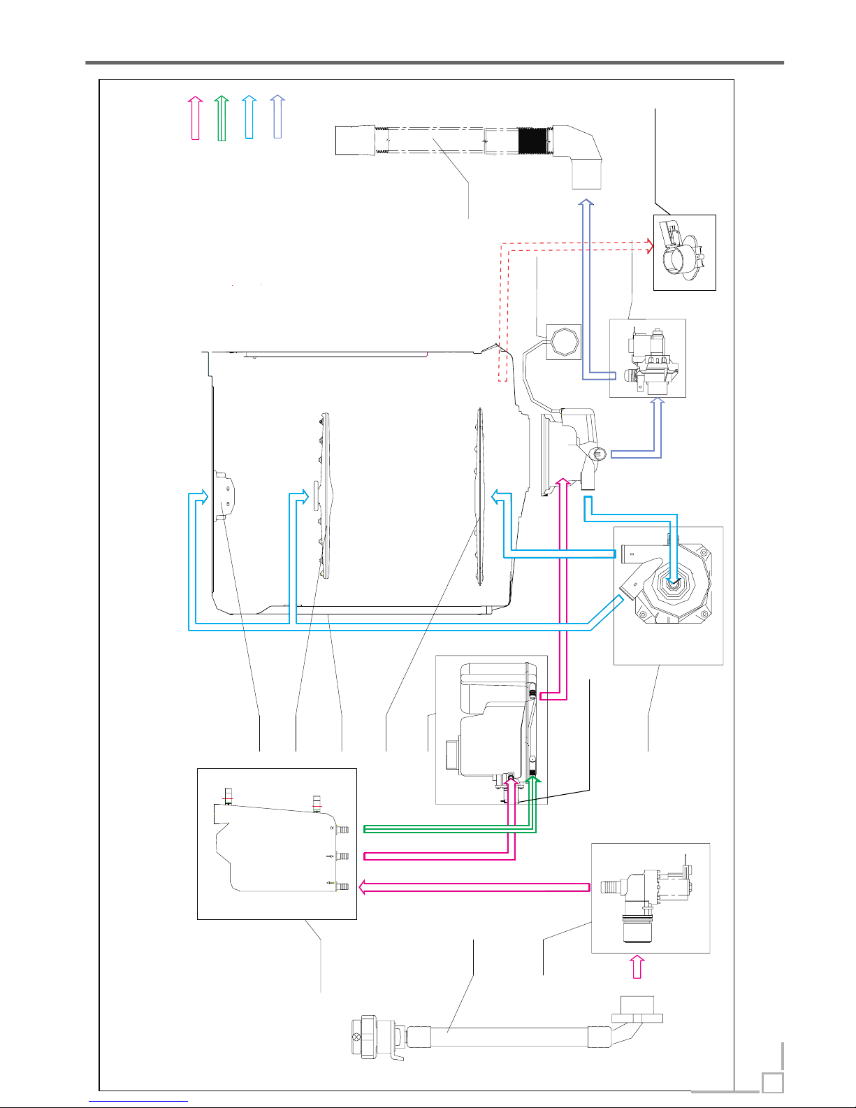
Process of water inlet (indicated by magenta route)
Process of cycle washing (indicated by blue route)
Process of regeneration (indicated by green route)
In this process, regeneration water route is cut off, main water route is open. The water in the main water
route is softened when pass through the softener, and then enter in the tub. During this phase, some of inlet
water will be stored in the air breaker to be regenerating water.
Cycle washing action is driven by washing pump motor. Water can obtain the power during it passing through
the working washing pump, then be pumped into spray arm, pass from spray arm nozzles, over the dishes,
into sump ,where connect to washing pump, and to get in the next water cycle.
Regeneration valve is open, the regenerating water dissolve salt in the salt chamber of softener, and then
enter in the resin tank to reactivate the resin.
Water Circuit Function Description->
5
Page 7
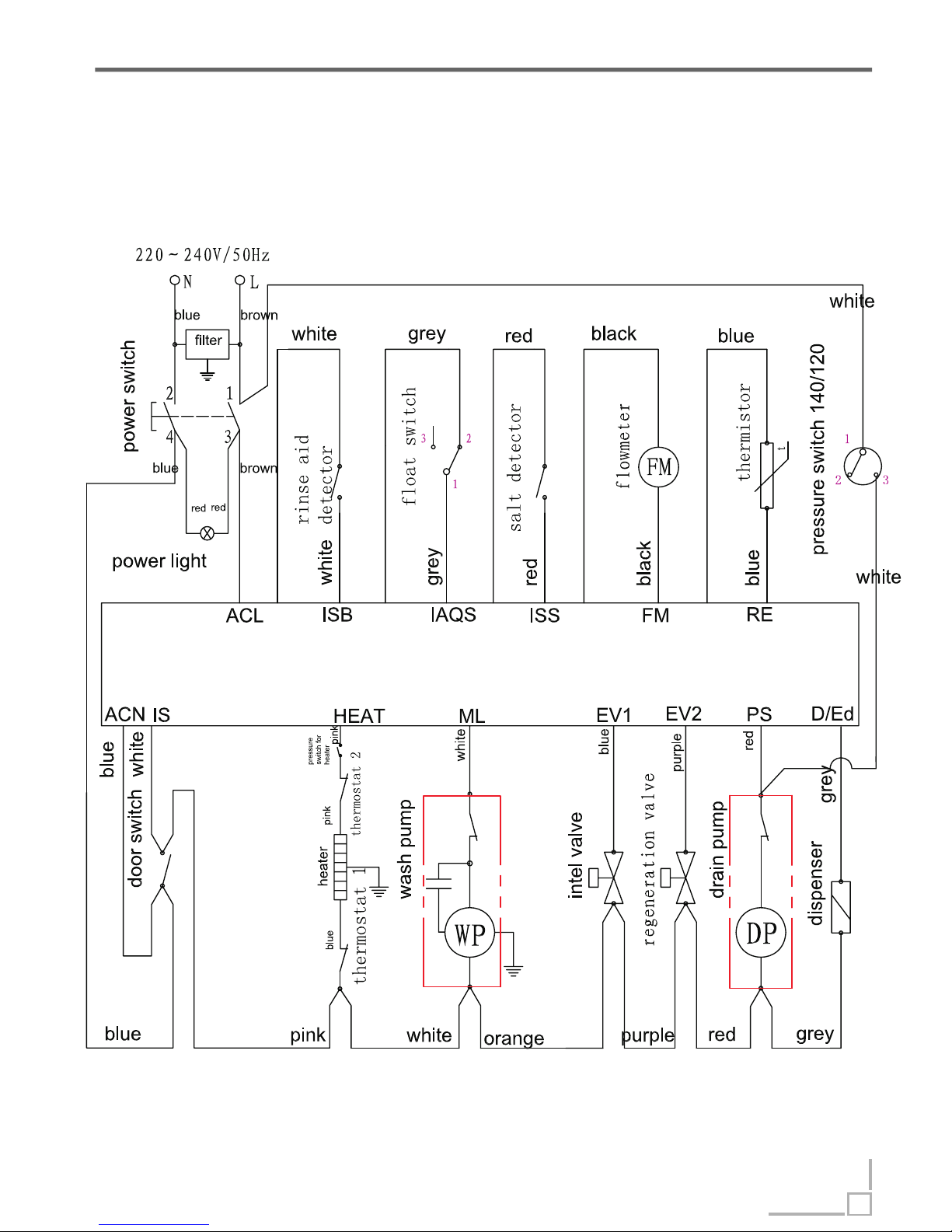
Circuit Schematic Function Description->
Circuit schematic diagram
6
LPR661 LPR659
Page 8
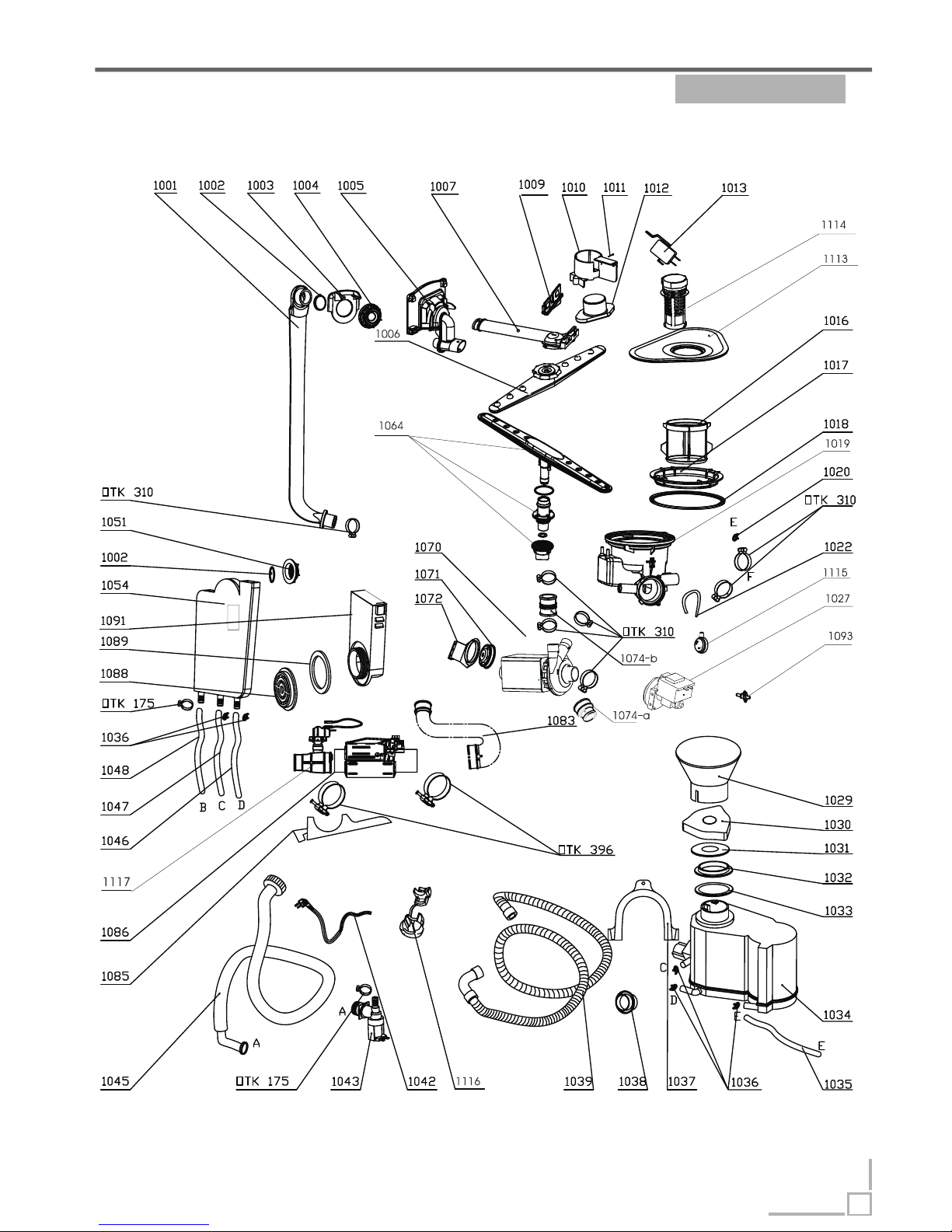
Exploded view Function Description->
7
LPR661
Please Note: Exploded view and part list of each model have
some different visions, so please refer to newest vision Midea
sent you.
Page 9
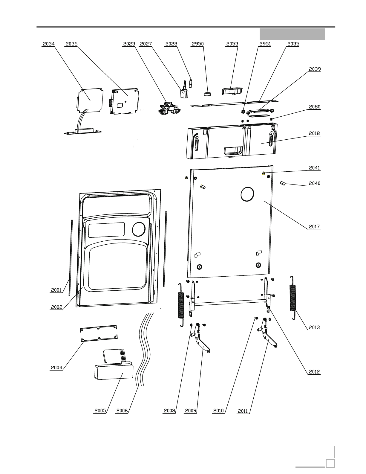
Exploded view Function Description->
8
LPR 661
Page 10
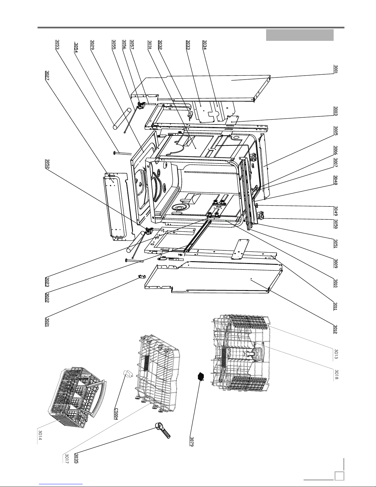
Exploded view Function Description->
9
LPR 661
Page 11
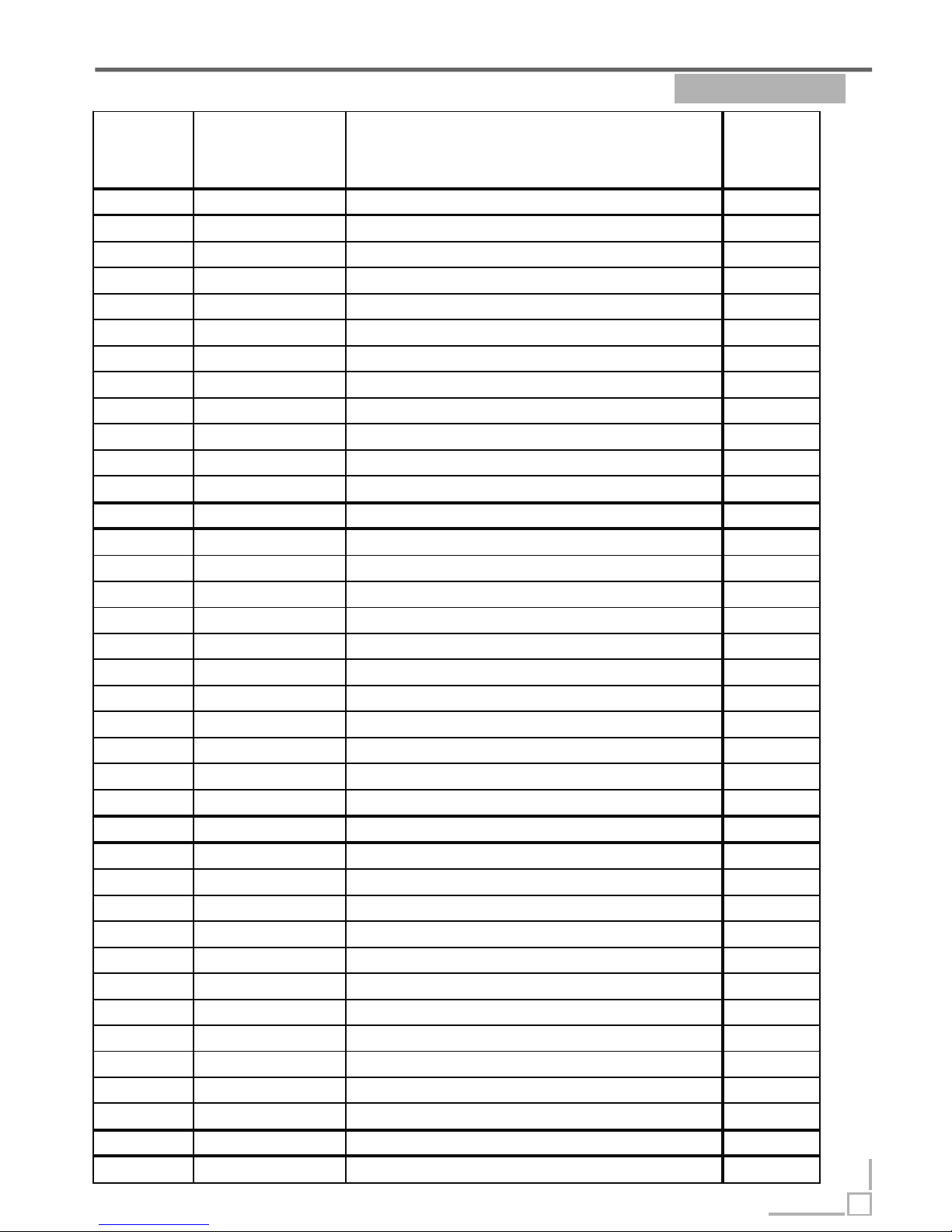
Part List Function Description->
10
LPR661
Serial
Number
Code Description Quantity
1001 673000900249 External pipe 1
1002 673001500005 O Ring I 31. 5X3.55 3
1003 673001800364 Guide casing 1
1004 673001600021 External pipe nut 1
1005 673001900016 Water dispenser 1
1006 673000300067 Upper sprayer 1
1007 673000900089 Upper sprayer pipe 1
1009 673001300041 Upper sprayer holder block 1
1010 673002300002 Float holder 1
1011 672000900012 Screw ST2.9x22 1
1012 673002300003 Float 1
1013 674000300060 Micro switch 1
1016 673002500047 Micro filter 1
1017 673001600022 Sump nut 1
1018 673001500016 Sump gas ket 1
1019 673000700081 Sump 1
1020 672000700028 Clamp 12.7 1.8 1
1022 673000900073 PVC hos e 1
1027 674000600106 Drain pump 1
1029 673002200043 Salt filler 1
1030 673002800050 Softener cover assembly 1
1031 673001700053 Softener cover gasket 1
1032 673001600039 Softener nut 1
1033 673001700001 Softener gasket 1
1034 674000700021 Softener 1
1036 672000700029 Clamp 14.5 1.8 1
1037 673006200003 Drain hose hook 1
1038 673001500002 Drain hose holder 1
1039 673000900186 Drain hose 1
1042 674000000092 Power cord 1
1043 674000200002 Iniet valve 1
1045 673000900060 inlet hose assem bly 1
1046 673000900026 Regeneration hose 1
1048 673000900024 Inlet hos e of air breather 1
1051 673001600055 Air breather nut 2
1054 673002700008 AWECO Flowmeter 1
1064 672000600013 Lower sprayer 1
1070 674000600047 Washing pump 1
Page 12
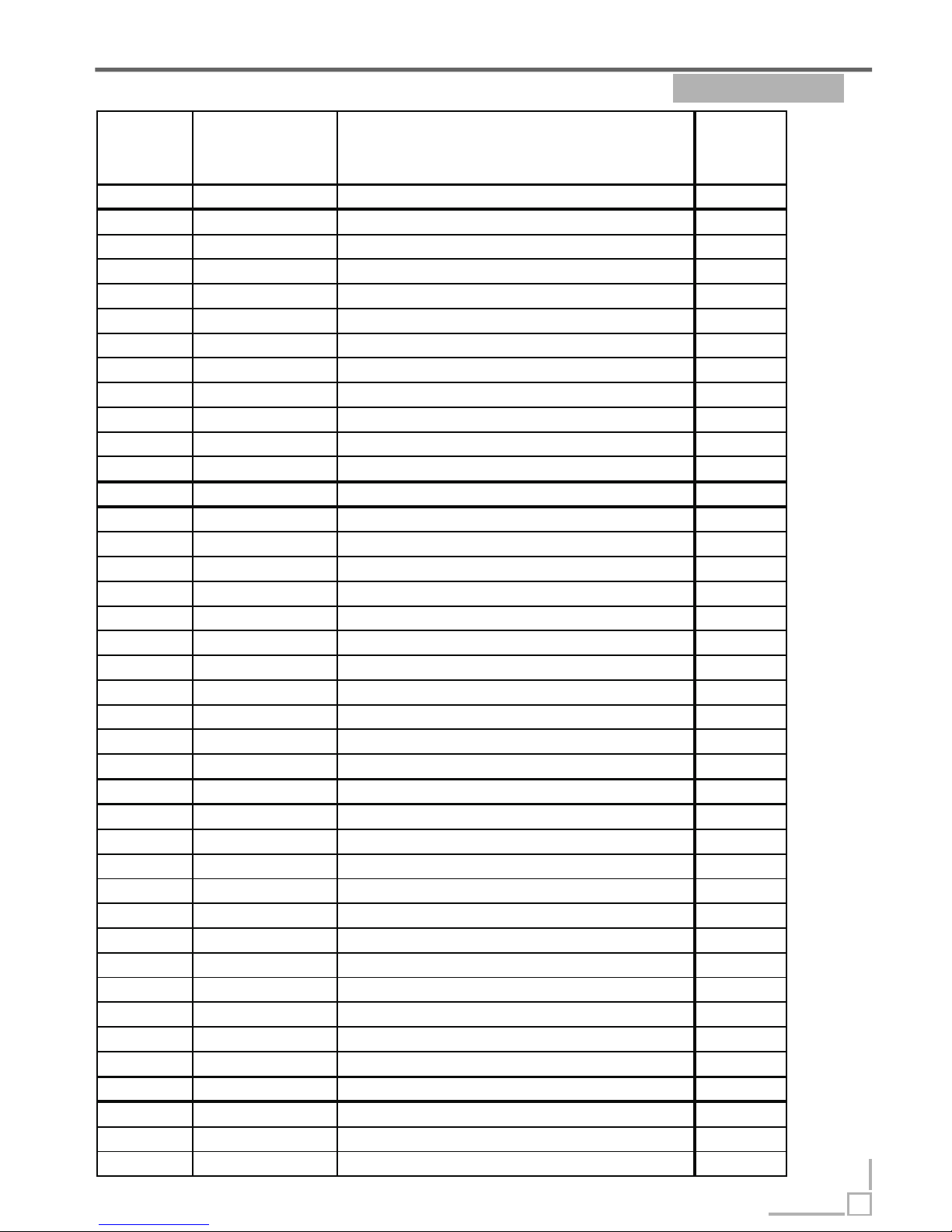
Part List Function Description->
11
LPR661
Serial
Number
Code Description Quantity
1083 673000900045 Bend connect hose 1
1085 673001400025 Heating element support 1
1086 674001100039 Heating elements 1
1088 673001600024 Water inlet nut 1
1089 673001500019 Water inlet gasket 1
1091 673002600035 Water inlet 1
1093 674000900038 Sensing device 1
1113 673002500048 plane filter 1
1114 673001300137
Scran collection 1
1115 674000300079 Pressure switch 1
1116 673001400083 power cord clasper 1
1117 674000300067 pressure switch assembly for heating elements 1
2001 673002000042 Door edge guard piece 2
2002 672002200150 Inner door 1
2004 672001700002 Dispenser bracket 2
2005 674000800032 Dispenser 1
2006 674000100453 Wiring harness 1
2008 672000500006 Ring Φ64
2009 672001300029 Left hinge 1
2010 672001200012 Joint pin 2
2011 672001300030 Right hinge 1
2012 672001300024 Door gemel assembly 1
2013 672000100008 Door spring 2
2017 672001800315 Outer door 1
2018 673000404251 Front panel 1
2023 673001800513 Handle assembly 1
2027 674000300065 Power switch 1
2028 674000400011 Red pilot lamp 1
2034 674001020203 Control board 1
2035 672000300989 Control panel film 1
2036 673002400095 Control board box 1
2039 673002800090 Window 1
2040 673001800365 Screw sleev e 2
2041 673000700005 Sleeve cover 2
2053 673002800041 Control panel cover 1
2080 672000100012 button spring 3
2950 673000800906 Power button 1
2951 673000800905 Program key 3
3001 672001600212 Left side panel 1
3003 672002100058 Lower rear crosspiece 1
Page 13
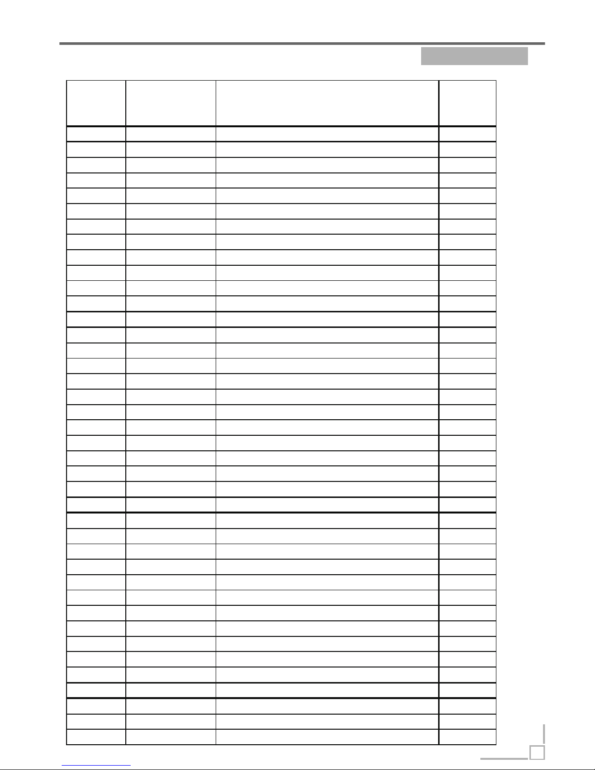
Part List Function Description->
12
LPR661
Serial
Number
Code Description Quantity
3005 672001500008 Upper rear crosspiece 1
3006 673001300061 door clamp 1
3007 672001400039 door lock 1
3009 672001500246 Upper front crosspiece 1
3010 673001700057 Tank gasket 1
3011 672002100057
Upright right assembly 1
3012 672001600211 Right panel 1
3013 673001300102 Upper basket cup holder 4
3014 673002200099 Cutlery bas ket 1
3017 672000800210 Lower basket 1
3018 672000800255
Upper basket
1
3021 673001300044 Rail block 2
3022 672001700005 Rail 2
3023 673001400056 Rail support ass embly 4
3027 672001500303
Lower front crosspiece 1
3029 672002000066 Tray assembly 1
3032 673001700010 Tank band bracing block 2
3033 672001500202 Lower rear crosspiece 1
3034 672001500007 Middle rear crosspiece 1
3035 673002200079 Measurable spoon 1
3048 672001100004 Adjust steel rope 2
3049 672002300002 Adjust nut 2
3050 673001300012 Top board hook 2
3051 672001100003 Adjust screw 2
3052 673001400145
Right adjuster holder assem bly 1
3053 672001400005 Front foot 2
3054 673003000001 slide 2
3055 672001100002 Adjustable pole 2
3056 673001400146 Left adjuster holder assembly 1
3057 672001400006 Back foot 2
3079 673002200091
3 in 1 tablet container
1
1035+1047 673000900224 Softener pipe 2
1071+1072 672000200054 Washing m o tor support 1
1074- a 673000900140 Connec t hose a 1
1074- b 673000900182 Connec t hose b 1
C5004 673006200004 rinsing agent cup 1
OTK 175 672000700004 OTK 175 4
OTK 286 672000700003 OTK 286 1
OTK 310 672000700001 OTK 310 6
OTK 396 672000700007 OTK 396 3
Page 14
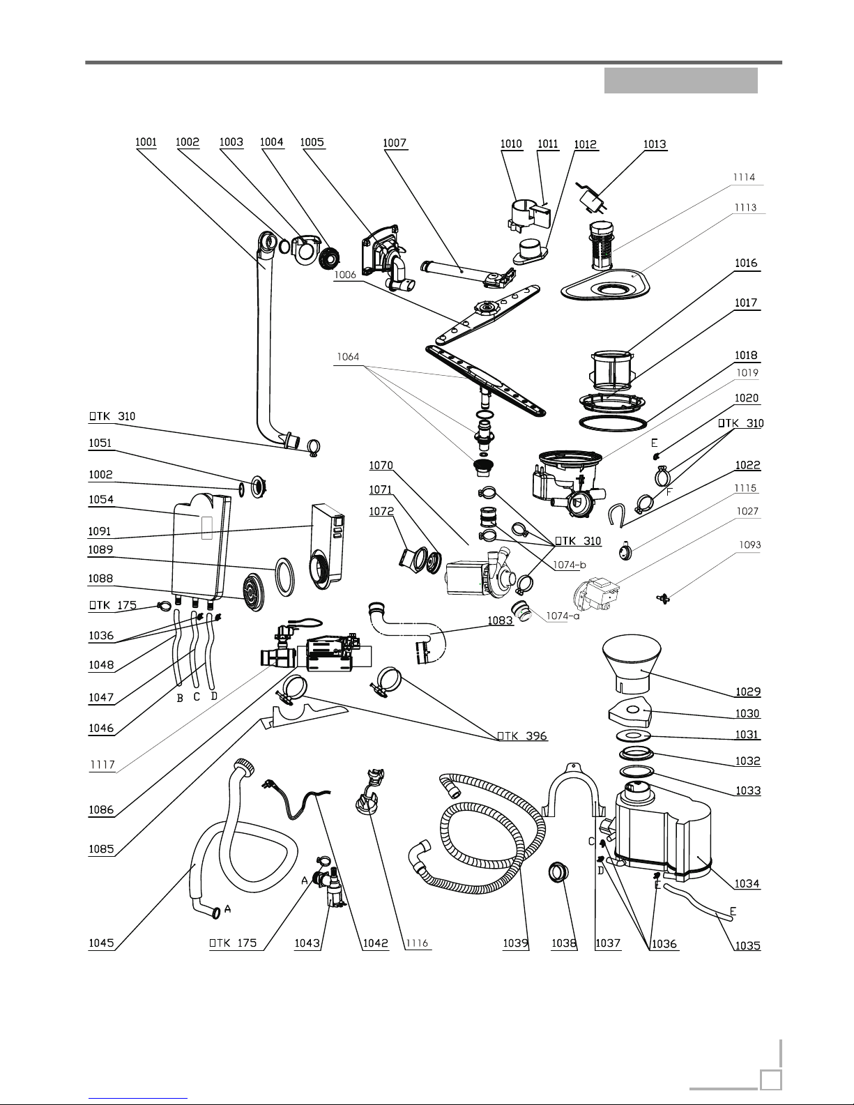
Exploded view Function Description->
13
LPR659
Page 15
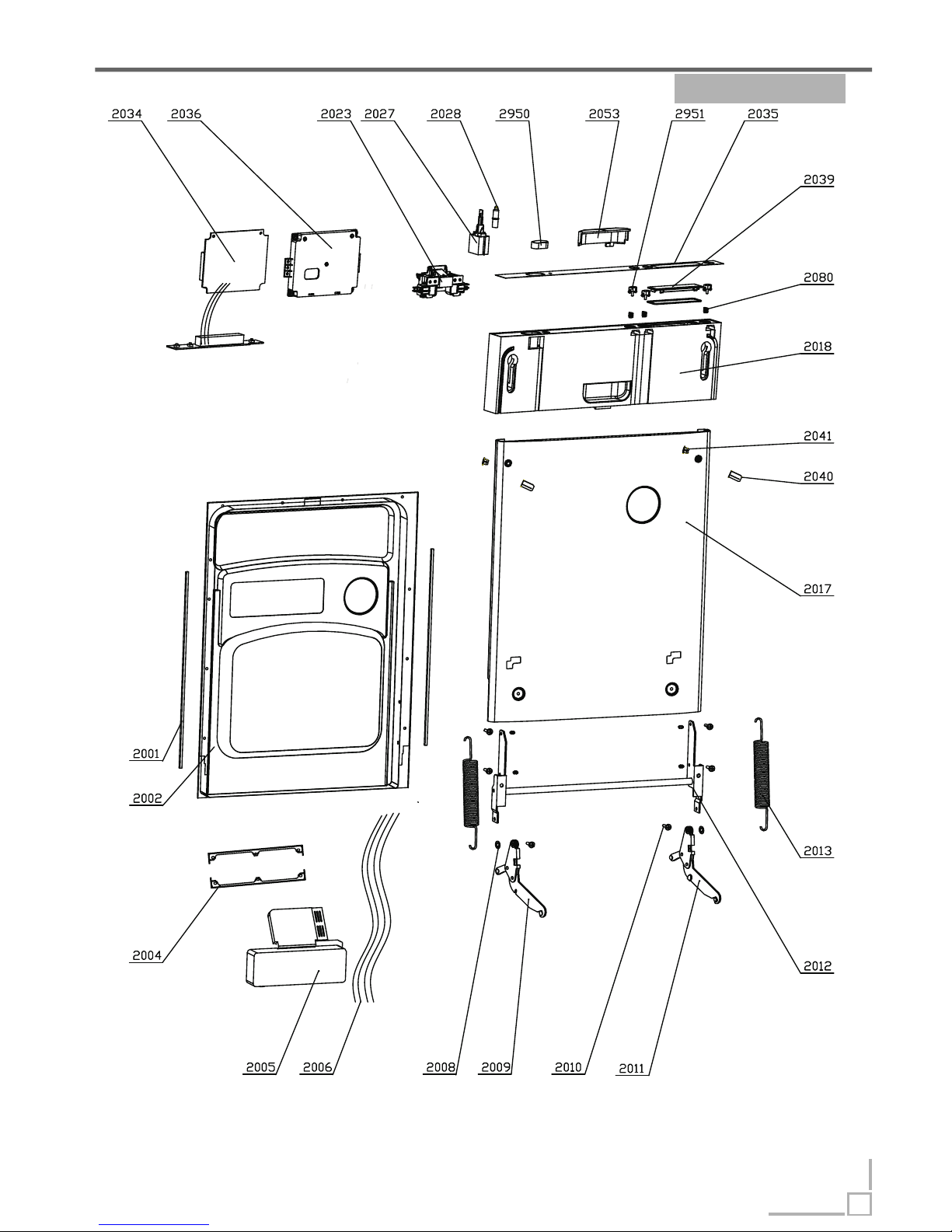
Exploded view Function Description->
14
LPR659
Page 16
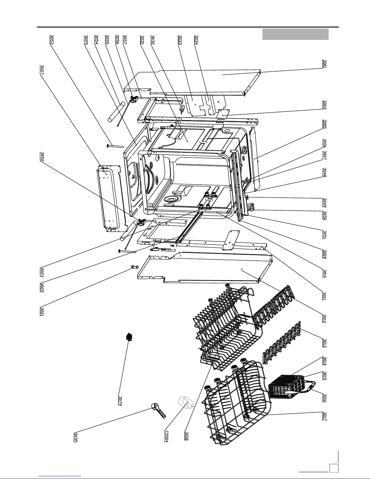
Exploded view Function Description->
15
LPR659
Page 17
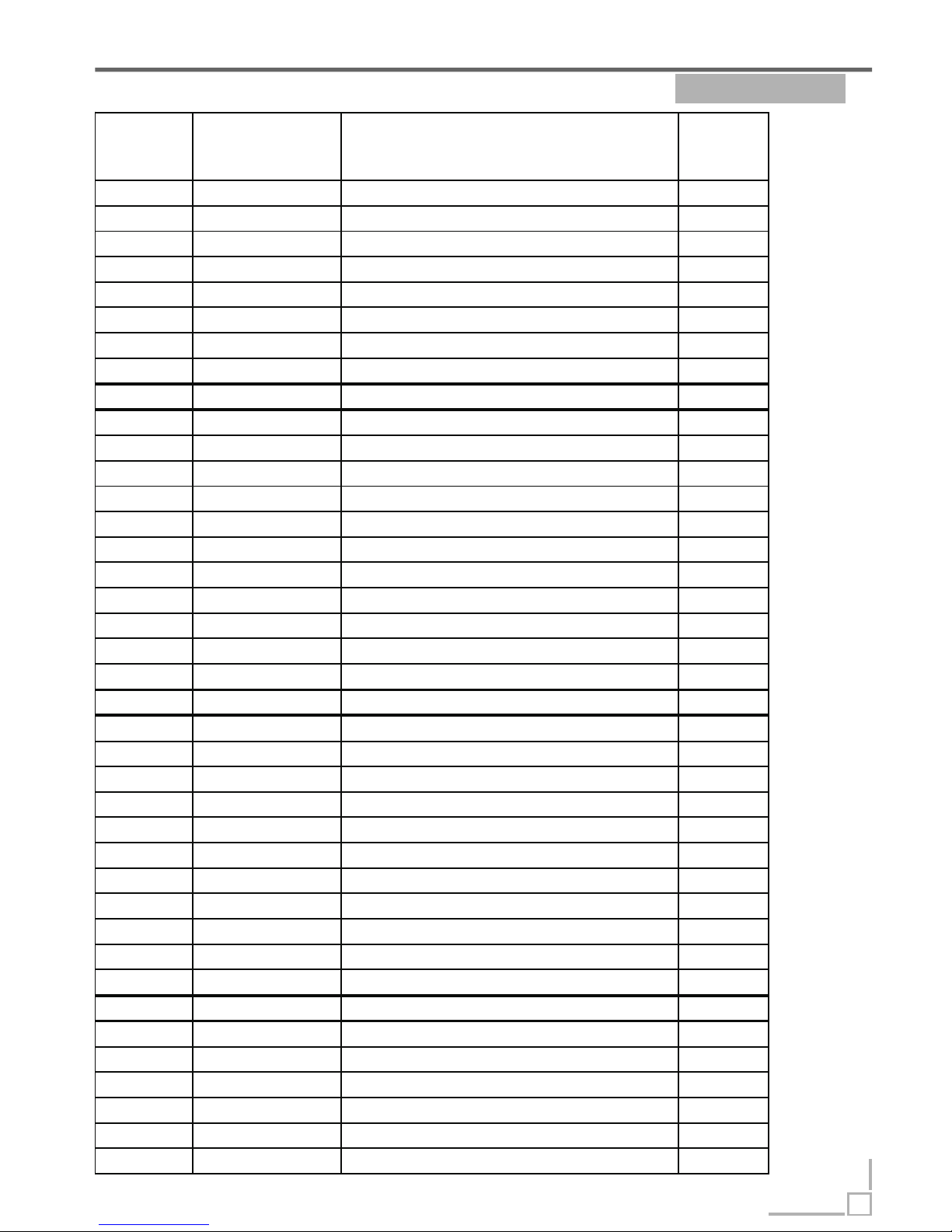
Part List Function Description->
16
LPR659
Serial
Number
Code Description Quantit y
1001 673000900249 External pipe 1
1002 673001500005 O Ring I 31.5X3.55 3
1003 673001800364 Guide casing 1
1004 673001600021 External pipe nut 1
1005 673001900016 Water dispenser 1
1006 673000300050 Upper sprayer 1
1007 673000900195 Upper sprayer pipe 1
1010 673002300002 Float holder 1
1011 672000900012 Screw ST2. 9x22 1
1012 673002300003 Float 1
1013 674000300060 Micro switch 1
1016 673002500047 Micro filter 1
1017 673001600022 Sump nut 1
1018 673001500016 Sump gasket 1
1019 673000700081 Sump 1
1020 672000700028 Clamp 12.7 1.8 1
1022 673000900160 PVC hose 1
1027 674000600106 Drain pump 1
1029 673002200043 Salt filler 1
1030 673002800050 Softener cover assembly 1
1031 673001700053 Softener cover gasket 1
1032 673001600039 Softener nut 1
1033 673001700001 Softener gasket 1
1034 674000700021 Softener 1
1036 672000700029 Clamp 14.5 1.8 1
1037 673006200003 Drain hose hook 1
1038 673001500002 Drain hose holder 1
1039 673000900186 Drain hose 1
1042 674000000092 Power c ord 1
1043 674000200002 Iniet valve 1
1045 673000900060 inlet hose assembly 1
1046 673000900026 Regeneration hose 1
1048 673000900024 Inlet hos e of air breather 1
1051 673001600055 Air breather nut 2
1054 673002700008 AWECO Flowmeter 1
1064 672000600015 Lower sprayer 1
1070 674000600047 Washing pump 1
1083 673000900045 Bend connect hose 1
1085 673001400025 Heating element support 1
Page 18
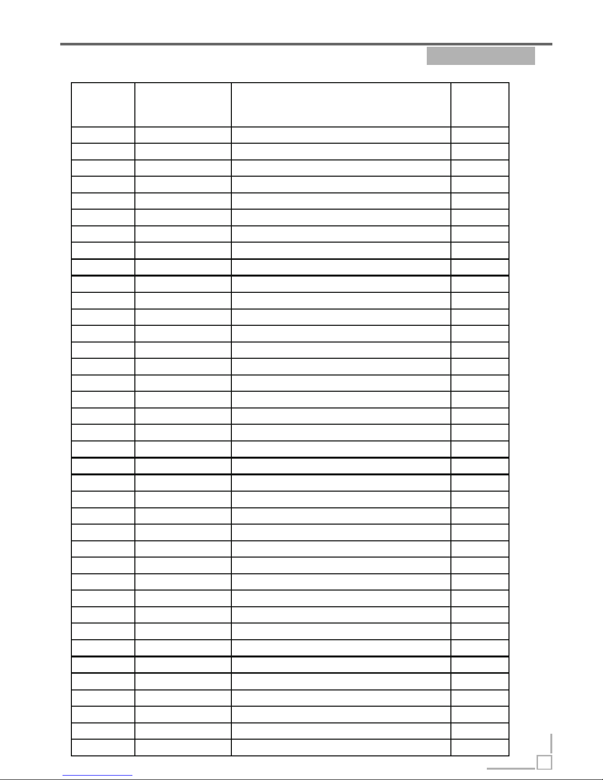
Part List Function Description->
17
LPR659
Serial
Number
Code Description Quantit y
1086 674001100039 Heating elements 1
1088 673001600024 Water inlet nut 1
1089 673001500019 Water inlet gasket 1
1091 673002600035 Water inlet 1
1093 674000900038 Sensing device 1
1113 673002500048 plane filter 1
1114 673001300137
Scran collection
1
1115 674000300079 Pressure switch 1
1116 673001400083 power cord clas per 1
1117 674000300067
pressure switch as sembly for heating elements 1
2001 673002000084 Door edge guard piece 2
2002 672002200165 Inner door 1
2004 672001700002 Dispens er bracket 2
2005 674000800032 Dispens er 1
2006 674000100445 Wiring harness 1
2008 672000500006 Ring Φ64
2009 672001300029 Left hinge 1
2010 672001200012 Joint pin 2
2011 672001300030 Right hinge 1
2012 672001300023 Door gemel assembly 1
2013 672000100004 Door spring 2
2017 672001800552 Outer door 1
2018 673000402168 Front panel 1
2023 673001800513 Handle assembly 1
2027 674000300065 Power switch 1
2028 674000400011 Red pilot lamp 1
2034 674001020117 Control board 1
2035 672000300990 Control panel film 1
2036 673002400095 Control board box 1
2039 673002800090 Window 1
2040 673001800365 Screw sleev e 2
2041 673000700005 Sleeve cover 2
2053 673002800041 Control panel cover 1
2080 672000100012 button spring 3
2950 673000800906 Power button 1
2951 673000800905 Program key 3
3001 672001600212 Left side panel 1
3003 672002100058 Lower rear crosspiece 1
Page 19
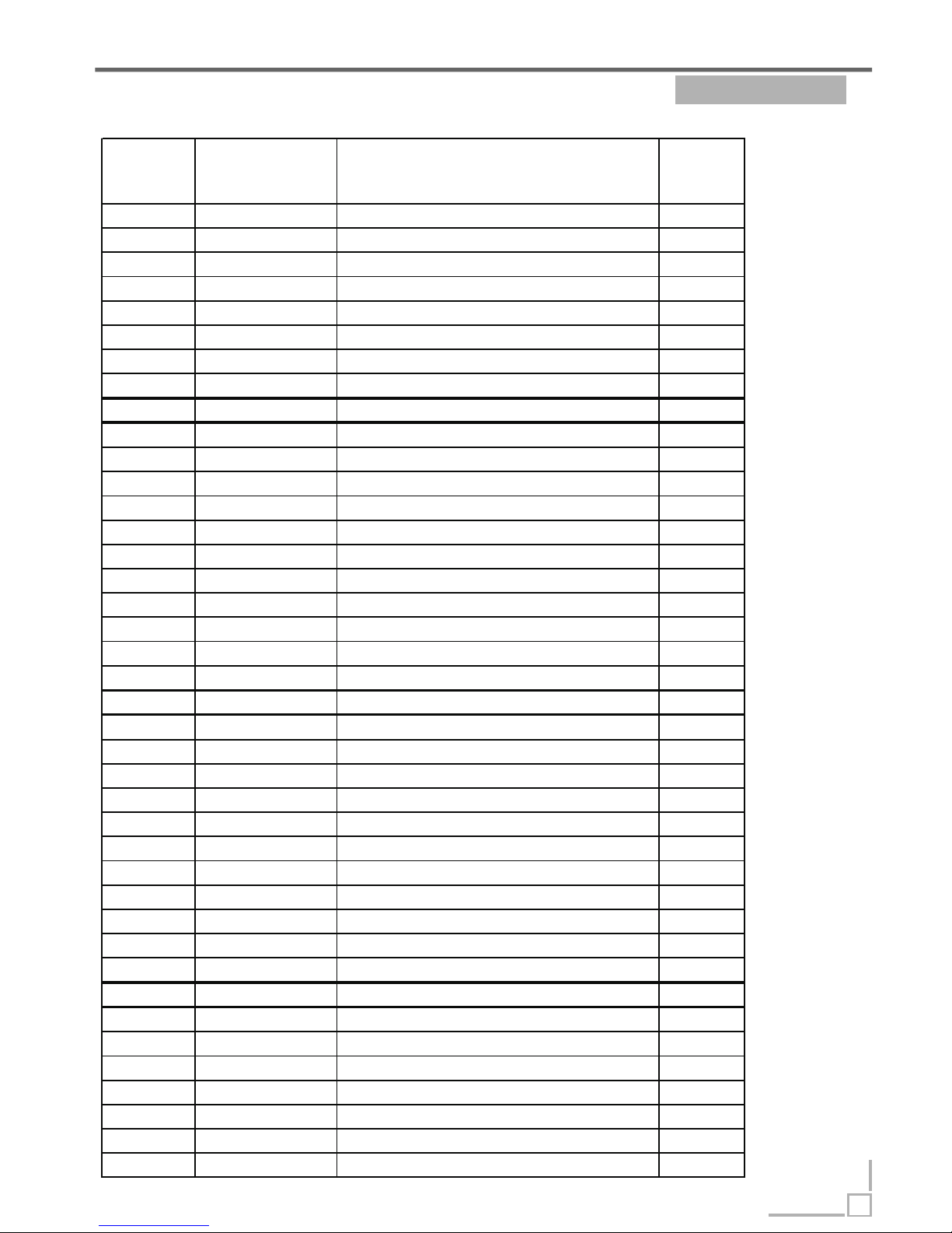
Part List Function Description->
18
LPR659
Serial
Number
Code Description Quantit y
3005 672001500003 Upper rear crosspiece 1
3006 673001300061 door clamp 1
3007 672001400039 door lock 1
3009 672001500247 Upper front crosspiece 1
3010 673001700056 Tank gasket 1
3011 672002100057
Upright right assembly 1
3012 672001600211 Right panel 1
3013 673001300072 Upper basket cup holder 4
3017 672000800188 Lower basket 1
3018 672000800156
Upper basket 1
3021 673001300044 Rail block 2
3022 672001700005 Rail 2
3023 673001400056 Rail support assem bly 4
3027 672001500292
Lower front cr osspiec e 1
3029 672002000065 Tray ass embly 1
3032 673001700010 Tank band bracing block 2
3033 672001500200 Lower rear crosspiece 1
3034 672001500114 Middle rear crosspiece 1
3035 673002200079 Measurable spoon 1
3048 672001100004 Adjust steel rope 2
3049 672002300002 Adjust nut 2
3050 673001300012 Top board hook 2
3051 672001100003 Adjust screw 2
3052 673001400145
Right adjuster holder assem bly 1
3053 672001400005 Front f oot 2
3054 673003000001 slide 2
3055 672001100002 Adjustable pole 2
3056 673001400146
Left adjuster holder assembly 1
3057 672001400006 Back foot 2
3079 673002200091
3 in 1 tablet container
1
1035+1047 673000900224
Softener pipe
2
1071+1072 672000200054 W ashing motor support 1
1074- a 673000900140 Connect hose a 1
1074- b 673000900182 Connect hose b 1
3014+3015+3016673002200080 Cutlery basket 1
C5004 673006200004 rinsing agent cup 1
OTK 175 672000700004 OTK 175 4
OTK 286 672000700003 OTK 286 1
OTK 310 672000700001 OTK 310 6
OTK 396 672000700007 OTK 396 3
Page 20
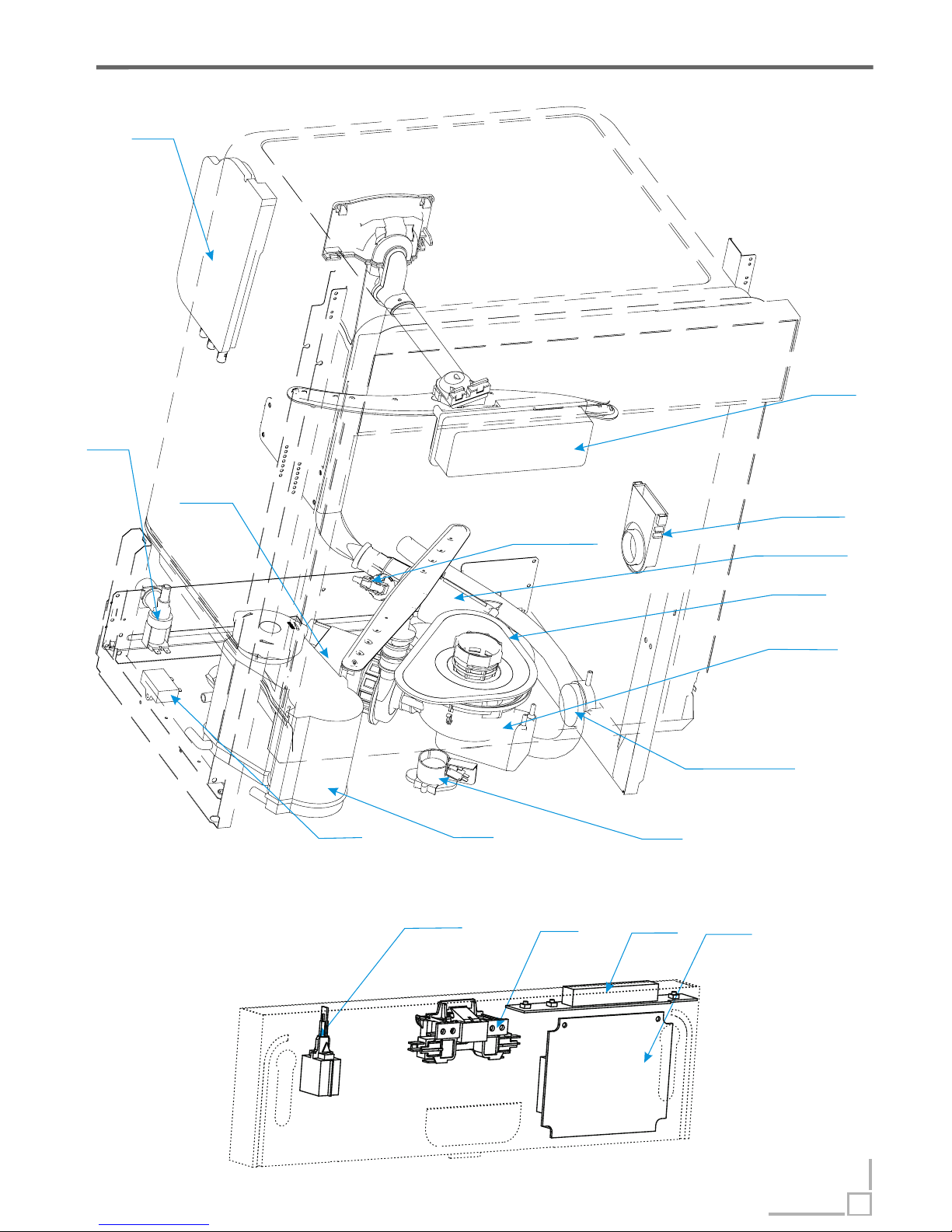
Location Theory of parts->
19
Inlet valve
Washing pump
Capacity
Softener
Flooding switch
Filter system
Heater
Anti-dry-heating
pressure switch
Dispenser
Sump
Water inlet
Air breaker
Power switch
Door latch
PCB
Pressure switch(140/120)
Display
Page 21
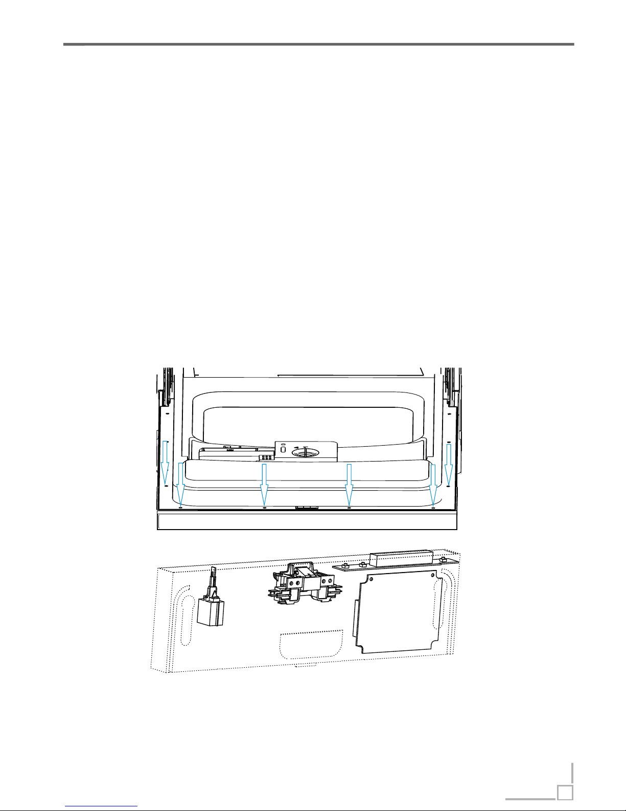
PCB Theory of parts->
Printed Circuit Board is the control center of dishwasher, which receive and
process signal from components, send order to components and deal with the
feedback information, etc.
Removing the control panel
The control panel can be removed from dishwasher door.
1. Remove the six screws securing the control panel to the door.
2. The control panel will drop down and be free of the door. But, the wiring will
still connected to the control panel.
S
S
08
1
212
on
Off
Access PCB
3. Disconnect the connector form PCB.
4. Remove the screws securing the PCB to control panel.
5. Remove the PCB.
6. Reverse the above procedure to install.
PCB
20
Page 22
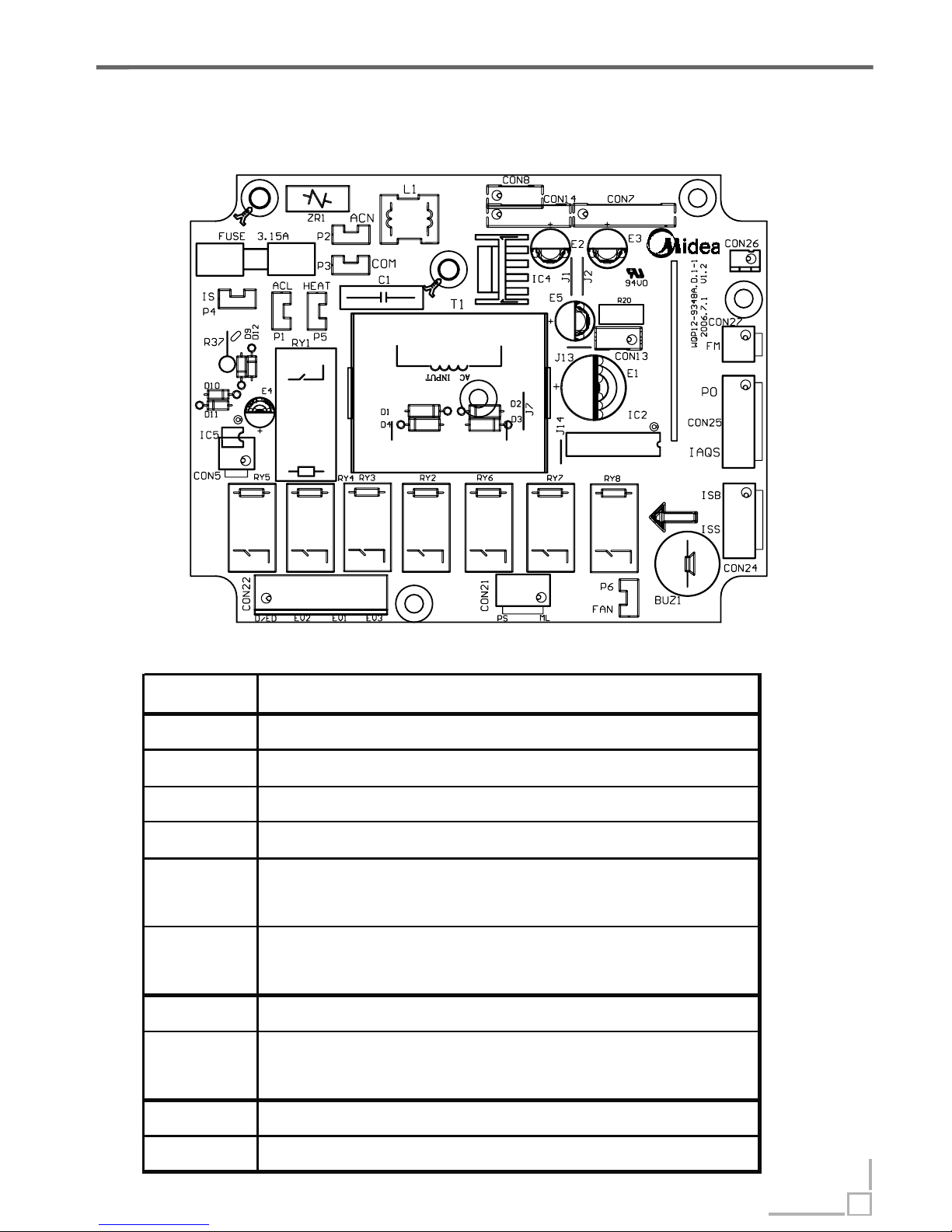
PCB Theory of parts->
Map of PCB
Description
21
Mark Function
HEAT Output for Heating Elem ent
ACL Input of liv e wire
ACN Input of bull line
IS Input of Door Switc h
CON21
Output for Washing Pump(ML) and Drain
Pump(PS)
CON22
Ouput for Dispenser(D/ED), Soft ener(EV2),
Halfload Valve(EV3) and Inlet V alve(EV 1)
CON24 Salt detect(ISS), Rinse detect(ISB)
CON25
Overflow detect(IAQS), Pressure Switch
det ect(PO)
CON26 Thermister(RE)
CON27 Flowmeter(FM)
Page 23
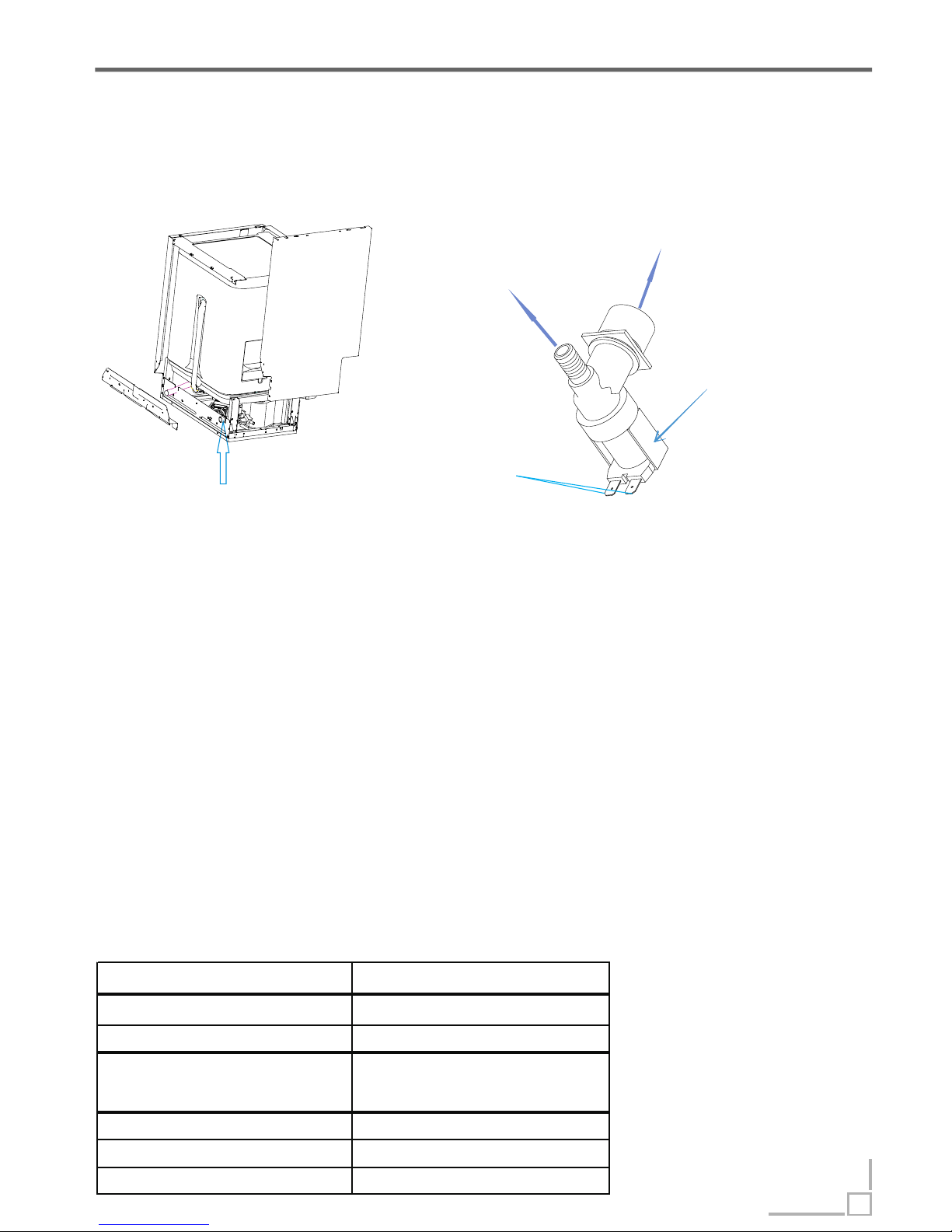
Technical data
Location of inlet valve
Appearance
Inlet Valve Theory of parts->
The work principle
The inlet valve is electromagnetic valve that decide whether water enter or
not. Valves are normally closed. Each time the appliance requires water, the
controller will convey an electric signal to the coils to open the valves.
The inlet valve consist of electric coil, valve body, valve pole, filter etc.
In a word, the electromagnetic valve can act to allow water enter into machine,
when it receive the order given by controller.
to air breaker
connect to
inlet water hose
terminals
electric coil inside
The defeat point
1. The valve coil is broken, so the valve can’ t open. It will cause the E1 error.
2. The filter is jammed, so water can’t enter. It will cause the E1 error.
3. The connector is loose, so the valve can’ t open. It will cause the E1 error.
4. The valve pole is rusted or locked by dreg, so the valve can’t open or close.
It will cause the E1 or E4 error.
Nominal voltage
220-240VAC
Frequency
50/60Hz
Resistance
Approx:3.4-4.3kΩ
100%ED T25
3min/5min T60
Flux
4L/min ±15%
Power
6W
Work Pressure 0.04-1MPa
Work duty
22
Page 24
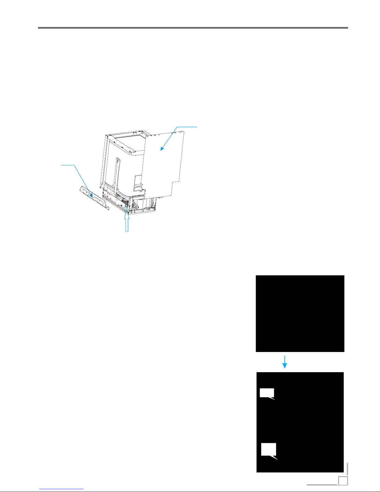
Inlet Valve Theory of parts->
1. Left side panel
2. Middle rear
crosspiece
Inlet valve
Access inlet valve
1. Disconnect power.
2. Remove the water inlet hose. (Note : Be careful of remain water drop.)
3. Remove the left baseboard and middle rear crosspiece.
4. Disconnect the 2 terminal
lugs from the inlet valve.
5. Push the valve from the
lower rear crosspiece to take
it off.
6. Remove the clamp and
disconnect the inlet hose (to
air breaker) from the water
valve.
7. Reverse the above
procedure to install.
1.Open the control panel and take out the PCB;
2.Unplug the CON3 and P4 wires , then use the
multi-meter shelf to measure resistance
between the blue wire (EV1) and white wire (IS),
the normal resistance is about 3.4K to 4.3 K .
3. I f the measured resistance is not correct, it
means the valve coil is broken or the connector
is loose. In this case, we should check the
connection first. If the problem hasn’ t been
solved by re-connection, we should replace the
valve..
4.If the resistance is OK, we need to inspect the
valve body.
Ω
ΩΩ
Inspect inlet valve
unplug
IS
Ev1
Check electric part
23
Page 25
Inlet Valve Theory of parts->
Check machine part
1. If the electric part is OK, we need to check the machine part.
2. Remove the baseboard, left baseboard, top panel, left side panel and
middle rear crosspiece.
3. Check the valve filter. if the valve filter is blocked, we need clear the
residues.
4. If the valve filter is clear and the valve can’ t inlet water, check whether valve
can act or not. If it isn’t , we need replace the valve.
5. If the water is continue entering, we need replace the valve.
24
Page 26
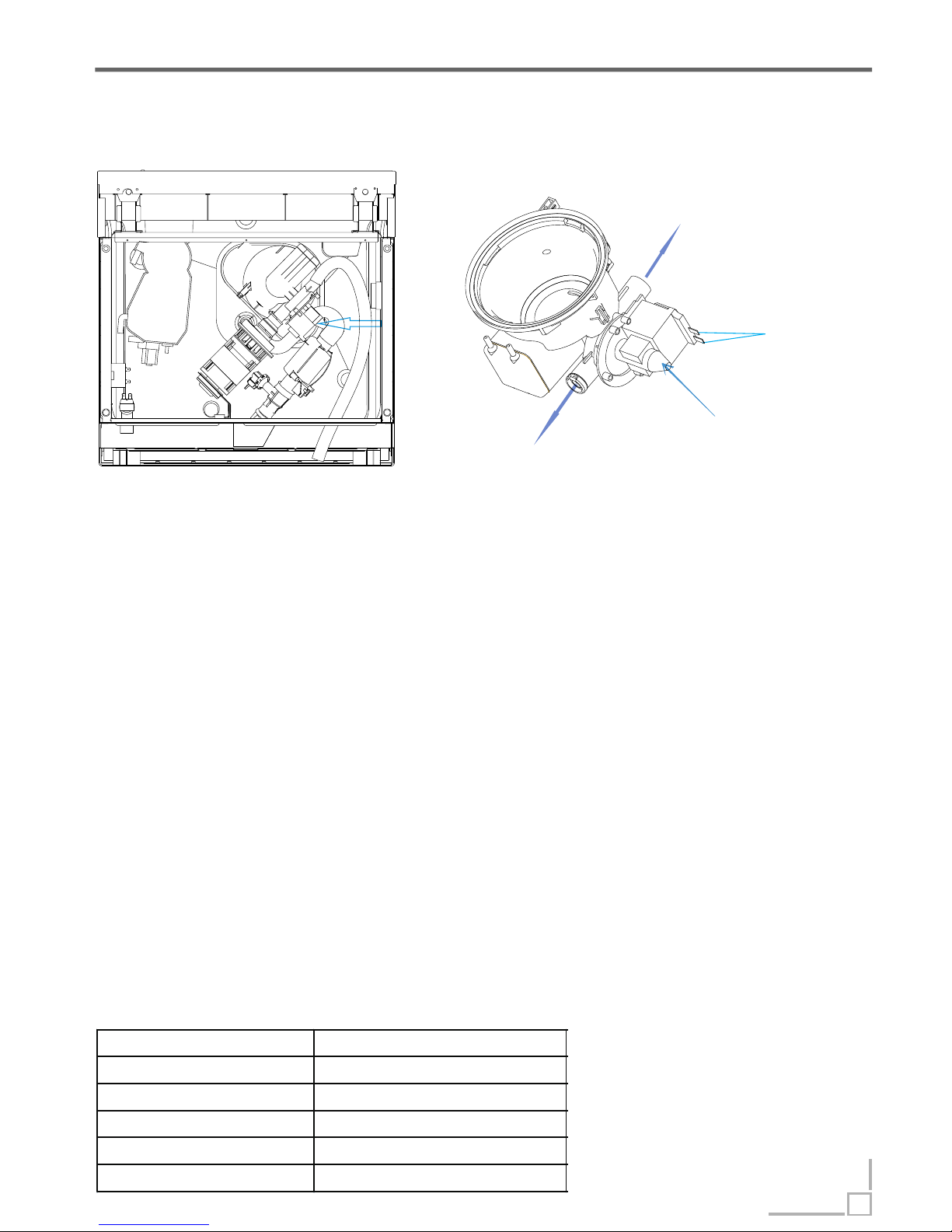
Drain Pump Theory of parts->
BViewottom
Location of Drain Pump
Technical data
The work principle
to washing pump
connect to drain hose
motor
terminals
Drain pump integrated into sump
The work principle
Drain pump consists of electrical motor, impeller, inlet and outlet.
Drain pump is a kind of pump driven by permanent magnet synchronous motor.
The rotor is made with permanent magnet material, the running inertia of rotor
is very small, the stator consist of silicon steel stack and coil. When the drain
pump is on power, the rotor will be very easy to start.
The defeat point
1. The motor coil is broken, so the drain pump can’t work. It will cause the E2 ,
E4 or E1 error .
2. The magnetism of motor rotor is weak, so drain pump cannot work. It will
cause the E2, E4 or E1 error .
3. The connector is loose, so the drain pump can’ t work. It will cause the E2, E4
or E1 error .
4. The rotor is locked by residues, so the drain can’t work . It will cause the E2,
E4 or E1 error .
5.The drain pump assembly rack is loose, it will cause noise.
6.The non-return valve is bad, the remain water is too much.
Explanatory notes: failure of drain pump may cause E1, because
Nominal voltage 220-240VAC
Frequency 50Hz
Resistance 150-220Ω
Delivery height 1M
Delivery performance ≥17l/min(230VAC)
Rate current ≤0.20A
25
Page 27
Drain Pump Theory of parts->
Check the machine part
1. If the electric part is OK, we need to check the machine part.
2. Remove bottom board.
3. If the non-return valve is wrongly assembled, the tub will remain much water. We need to
re-assemble the non-return valve.
4. If the drain pump is working, but no water drain out or just a little. We should check the
drain hose or drain body.
1. Drain off the water in the dishwasher,
and disconnect the power supply
(Note : Make sure to remove remained
water in the dishwasher. If not, wet the
floor.)
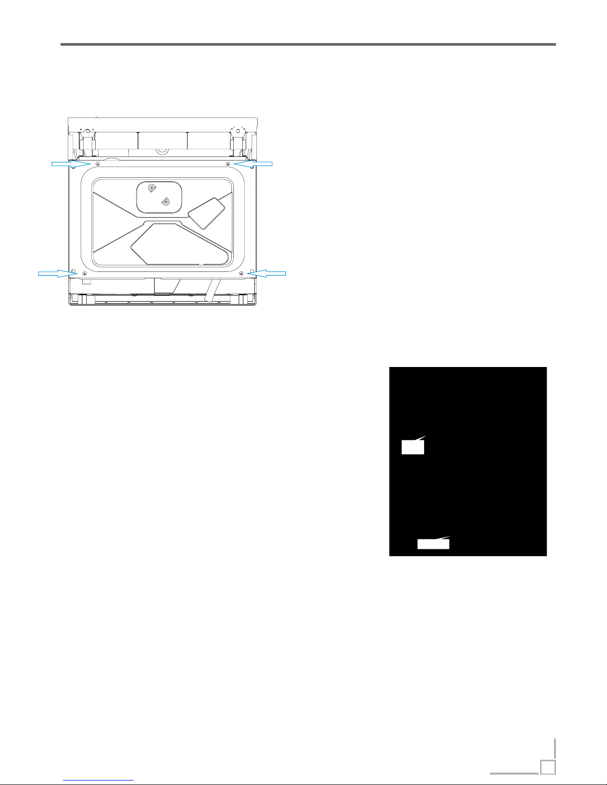
2. Remove four screws on bottom, and
then remove bottom board.
3. Label and disconnect the two terminal
lugs from the drain pump.
4. Remove screws securing the drain pump
to sump, then remove drain pump.
5. Reverse the above procedure to install.
。
Access drain pump
Inspect drain pump
Check the electric part
1.Open the control panel and take out the PCB;
2.Unplug the CON4 and P4 wires, then use the multimeter shelf to measure the red wire (PS) and white wire
(IS), the normal resistance is about 150 to 220 .
3. If the measured resistance is not correct, it means the
pump coil is broken or connector is loose. In this case, we
should check the connection first. If the problem hasn’ t
been solved by re-connection, we should replace the
drain pump.
4.If the resistance is OK, but it also can’ t work, maybe the
magnetism is too weak, so we need to replace the drain
pump.
Ω
ΩΩ
IS
PS
26
Page 28
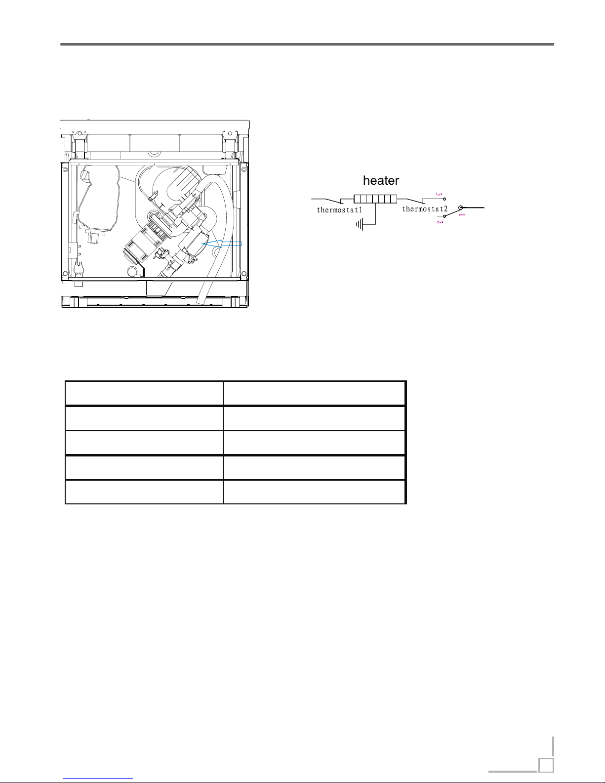
The defeat point
1. The heater coil is broken, so the heater cannot work. It will cause the E3
error.
2. The thermostat is active, so the heater cannot work. It will cause the E3
error.
3. The connector is loose, so the heater cannot work. It will cause the E3 error.
Heater Theory of parts->
BViewottom
The work principle
Technical data
Location of Heater
pressure switch
Nominal voltage 230VAC
Rating power 1800W
Resistance 29.265 1.463Ω
Thermastat1 98℃
Thermastat2 229 ℃
27
Page 29
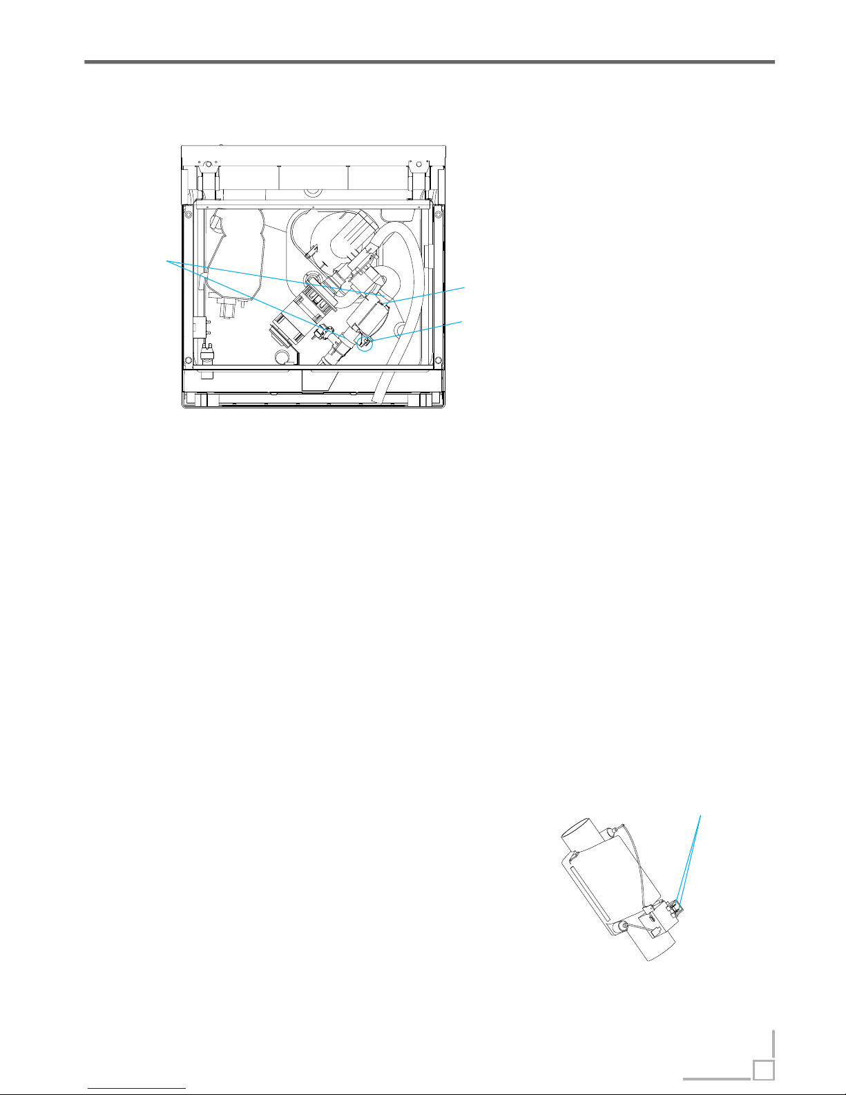
Inspect heater
1. Remove bottom board.
2. Use the multi-meter shelf to measure
resistance between the two terminals shown in right
picture, the resistance is about 29 to 31 .
3. If the measured resistance is not correct, it
means the heater coil or the thermostat is broken,
we should replace the heating element or the
thermostat.
Ω
ΩΩ
Heater Theory of parts->
BViewottom
Access heater
1. Drain off the water in the dishwasher, and disconnect the power supply.
(Note : Make sure to remove remained water in the dishwasher. If not, wet the
floor)
2. Remove bottom board.
3. Label and disconnect the terminals to and ground wire.
4. Remove the 2 clamps from the Heating element.
Caution: The clamp is easily damaged during removal and can’ t be reused.
Replace the old clamp with a new universal clamp .
5. Reverse the above procedure to install.
Clamps
Ground terminal
Terminals
(measure heater resistance)
terminals
28
Page 30
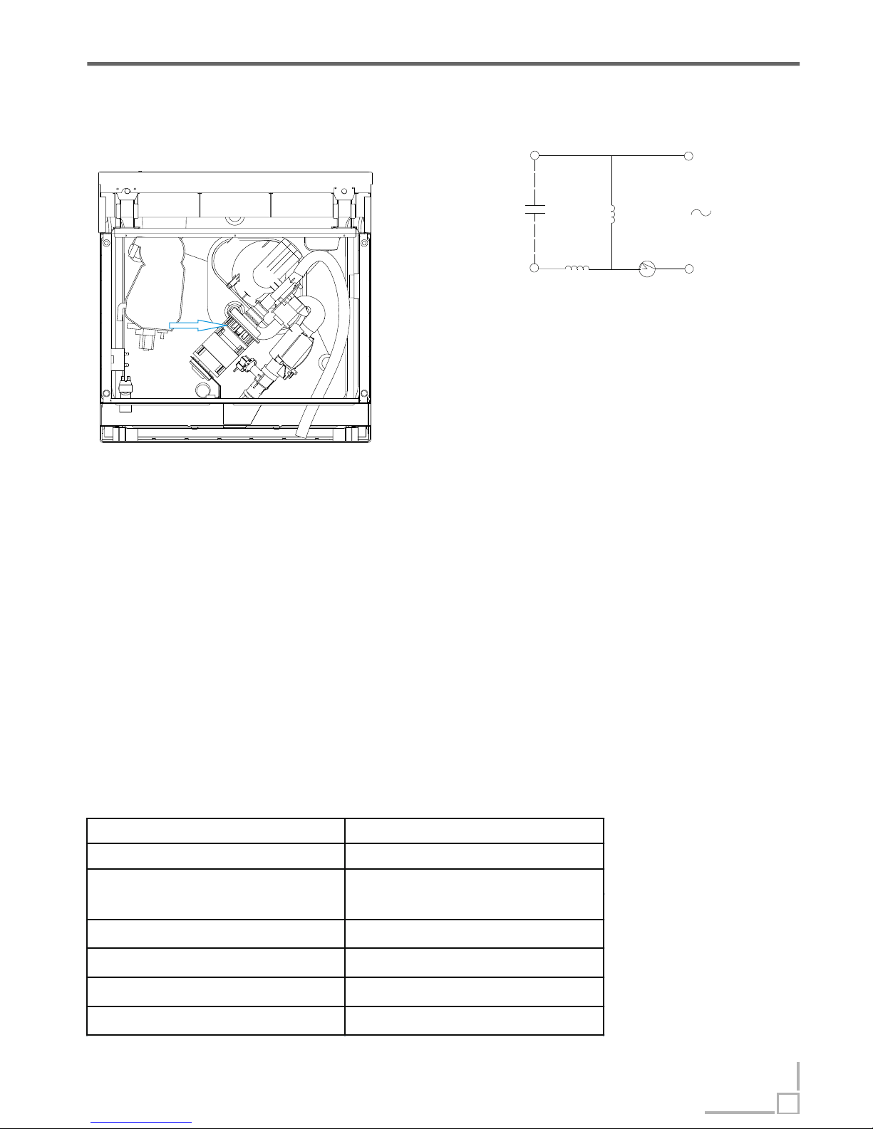
BLUE
BLACK
M
BLUE
A
150℃
RED
3uF/450V
Washing Pump Theory of parts->
BViewottom
Location of Washing Pump
Technical data
The work principle
Washing pump is a kind of asynchronism motor
with capacitor. The stator consist of silicon
steel stack and two coils, main coil and
assistant coil .
The defeat point
1. The motor coil is broken, so the wash pump can’t work. It will cause E3 error.
2. The motor rotor capacitor is weaken, so washing pump can’t start. In this
case, it will send out the electromagnetism noise. If it is continue electrifying
motor, the thermal protector will work. It will cause E3 error.
3. The connector is loose, the wash pump can’ t work. It will cause E3 error.
4. The rotor is locked by residues, so the wash pump can’t work . It will cause
the E3 error.
5.The drain pump assembly bracket is loose, it will cause noise.
6.If the machine hasn’ t been used for long time, there is a possibility the wash
pump can’ t starting.
M-main coil
A-assistant coil
Nominal voltage 220-240VAC
Frequency 50Hz
Main coil :84.8 7%Ω
Assistant:78.6 7%Ω
Delivery height 0.8m
Delivery performance ≥50l/min(230VAC)
Lock rotor current ≤1.50A
Operating current 0.65 10%(230VA C)
Resistance
29
Page 31
Washing Pump Theory of parts->
Check the machine part
1. If the electric part is OK, we need to check the machine part.
2. Remove bottom board.
3. Check the pump assembly, if the bracket is loose, it will bring the noise, we
need to tighten it.
4. If the wash pump cannot start and the machine hasn’ t been used too long,
maybe the seal element is bond.
5. If the drain pump is working, but no water out or just a little. We should check
the vane wheel.
Access Washing Pump
1. Disconnect power.
2. Remove bottom board.
3. Label and disconnect the 2 terminals to the capacitor.
4. Label and disconnect the 2 terminals to the motor wire connector.
5. Remove the clamp fastening the interconnect hose to the sump.
Caution: The clamp is easily damaged during removal and can’ t be reused. Replace the old
clamp with a new universal clamp (Dia-31.0mm)
6. Remove the clamp fastening interconnect hose to the lower nozzle .
7. Remove the clamp fastening interconnect hose to heater.
8. Remove the screw and disconnect the ground wire from the wash pump motor assembly.
Note: Do not attempt to remove the bolt and locknut connecting the motor mount to the
dishwasher frame.
9. Remove the motor pump assembly from the dishwasher.
10. Reverse the above procedure to install.
Inspect Washing Pump
Check the electric part
1.Open the control panel and take out PCB;
2.Unplug the CON4 and P4 wires, then use the
multi-meter shelf to test resistance between
two white wire (ML and IS), the normal resistance
is about 78 to 100 .
3. I f the resistance is not correct, it means the
pump coil is broken or the connector is loose, In
this case, we should check the connection first. If
the problem hasn’t been solved by reconnection, we would replace the washing pump.
4.If the resistance is OK but it cannot work, it
maybe the capacitor weakly, we need to replace
the capacitor.
Ω
ΩΩ
IS
ML
30
Page 32
The pressure switch consists of a moving diaphragm and disc which activate a
change over contact. The contact can be calibrated to trip and reset at the
desired pressure levels, The main application is to control the level of water in
appliances. May also provide flood protection.
In our production, the pressure switch is to control the level in appliance, like
83/63 serial. May also provide flood protection, like 140/120 serial.
Manufacturer:EMZ
11 - COM
12 - NC
14 - NO
Front view Back view
11
14
12
2
3
1
Back view
Front view
Manufacturer: Elbi
1- COM
2-NC
3-NO
Pressure Switch Theory of parts->
The work principle
31
Page 33
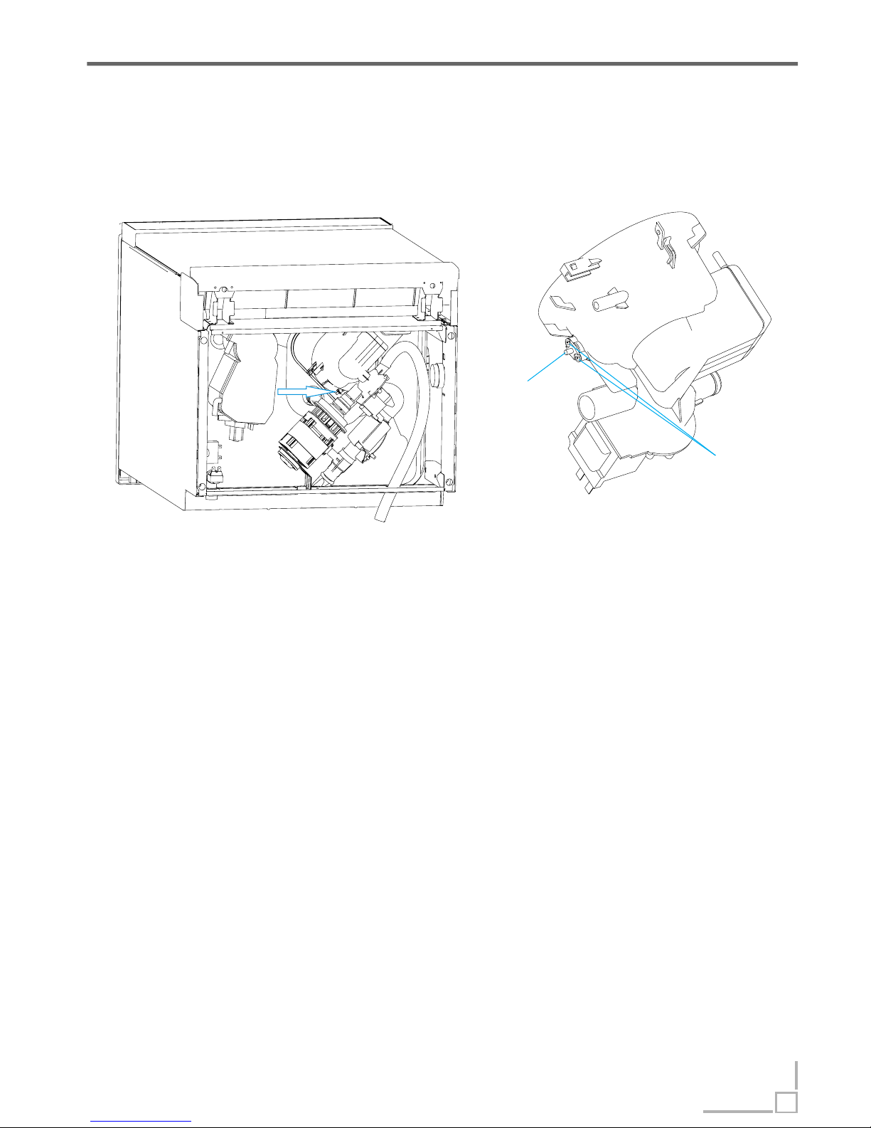
NTC Theory of parts->
NTC
BViewottom
Location of NTC
The work principle
The work principle
Negative Temperature Coefficient Thermistor is integrated into sump, which is
used for measuring temperature of water in the tub.
Access Washing Pump
1. Remove bottom board.
2. Remove two screws securing the NTC to sump(shown in above picture).
3. Take out NTC.
4. Reverse the above procedure to install.
screws
32
Page 34
NTC Theory of parts->
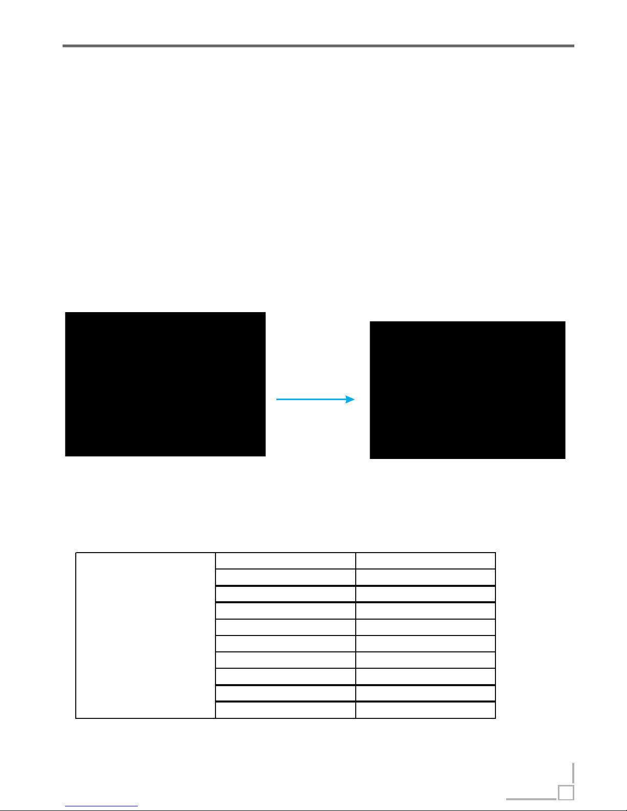
15℃ 17.48KΩ
20℃ 12.12KΩ
25℃ 10KΩ
30℃ 8.299KΩ
40℃ 5.807KΩ
50℃ 4.144KΩ
60℃ 3.011KΩ
70℃ 2.224KΩ
80℃ 1.667KΩ
85℃ 1.451KΩ
NTC
Inspect NTC
1.Open the control panel and take out PCB;
2.Unplug the RE connector(shown in below picture), then use the multi-meter
shelf to test resistance between two blue wire , the normal resistance is
shown in below table.
3. I f the resistance is not correct, it means NTC circuit has a problem. In this
case, we should check the connection first. If the problem hasn’ t been solved
by re-connection, we would replace the NTC.
Ω
unplug
NTC resistance table
33
Page 35
Flowmeter Theory of parts->
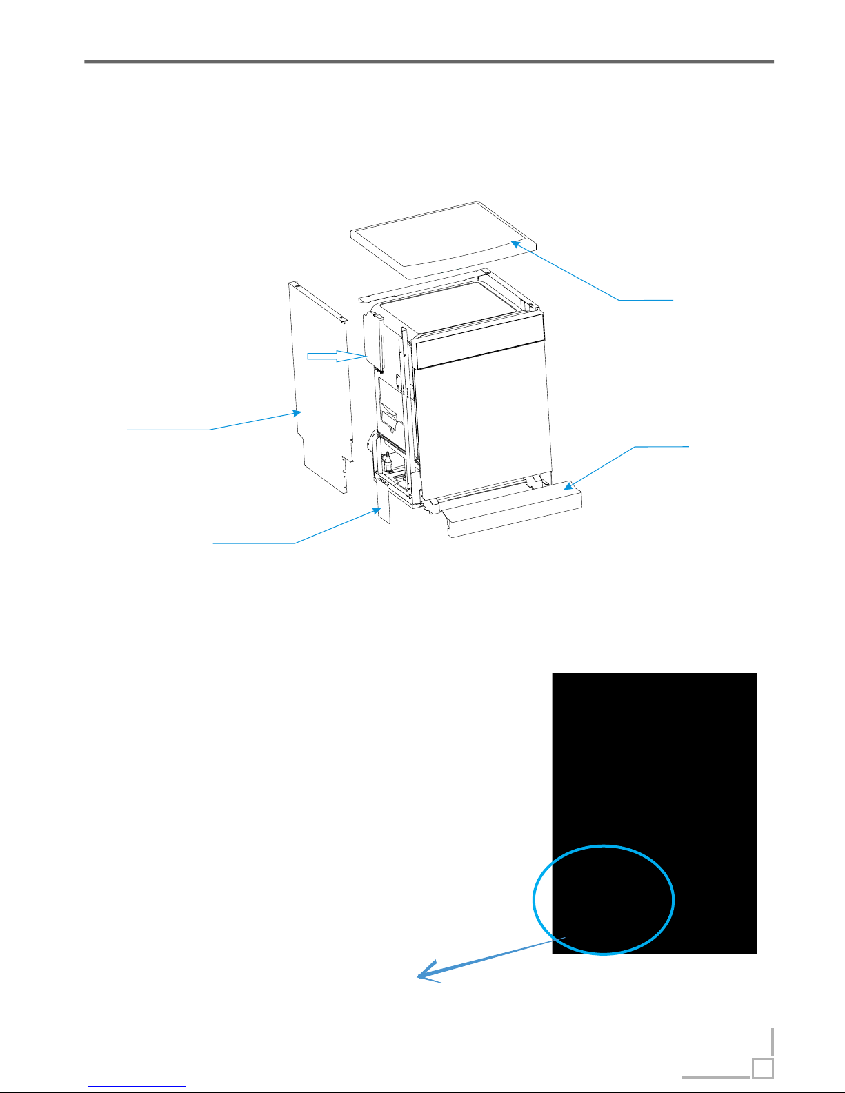
Location of Flowmeter
The work principle
Flowmeter
Flowmeter is integrated into Air Breaker. Function of
Flowmwter is measure how much water has entered in
appliance. it consists of impeller, tongue tube and
terminal, etc.
When water pass through the flowmeter, moving water
can rotate magnetic impeller, the tongue tube can sense
the impeller’s magnetic and send electronic pulses.
Top Panel
Side panel
Left Baseboard
Baseboard
34
Attention: Build in models have no Baseboard and left and
right baseboard, but adjustable baseboard.
Page 36

Inspect Flowmeter
1.Open the control panel and take out PCB;
2.Unplug the CON27 wire(shown in below picture), then use the multi-meter Diode shelf to
test whether electrical pulse is sent out from two black wires while water is passing through
flowmeter, or not.
3. If there is continual electrical pulse, the multi-meter will send out sound “de” continually.
4.if there is no electrical pulse, the multi-meter will not send sound. In this case, it means
something wrong with flowmeter circuit. We should check the connection first. If the
problem hasn’ t been solved by re-connection, we should replace the air breaker..
Access Flowmeter
1. Remove the baseboard, life baseboard, top panel and life side panel.
2. Remove the plastic nut inside tub, which secures the air breaker to tub.(Because
flowmeter is integrated into air breaker, replace air breaker if flowmeter has failure. )
3. Disconnect the wire and remove clamp fastening hose to air breaker.
4. Take out air breaker.
5. Reverse the above procedure to install.
Flowmeter Theory of parts->
35
Page 37
Test Program
How to activate Test Program
Attention
In order to check the operation of components of appliance and find out the
malfunction, we designed this program for technician.
Test Program
36
With the door opened and machine off, press the Program button. Hold down
the Program button and press the POWER button until the machine enter into
Test Program. The appliance will pause and stand by(as step 00). At the
moment, all the indicator which are under control are light and flash with
frequence of 2 Hz. Then, close the door to activate the test program.
During test program running you can press program button to jump into
next step except inlet valve step
Priority level of E4 is the highest. E4 operation is valid after other error
operations have done. When E4 operation has done, all the others are invalid.
In test program, E1, E3, E4, E6 and E7 are valid.
,
().
Page 38
Procedure ->Test Program
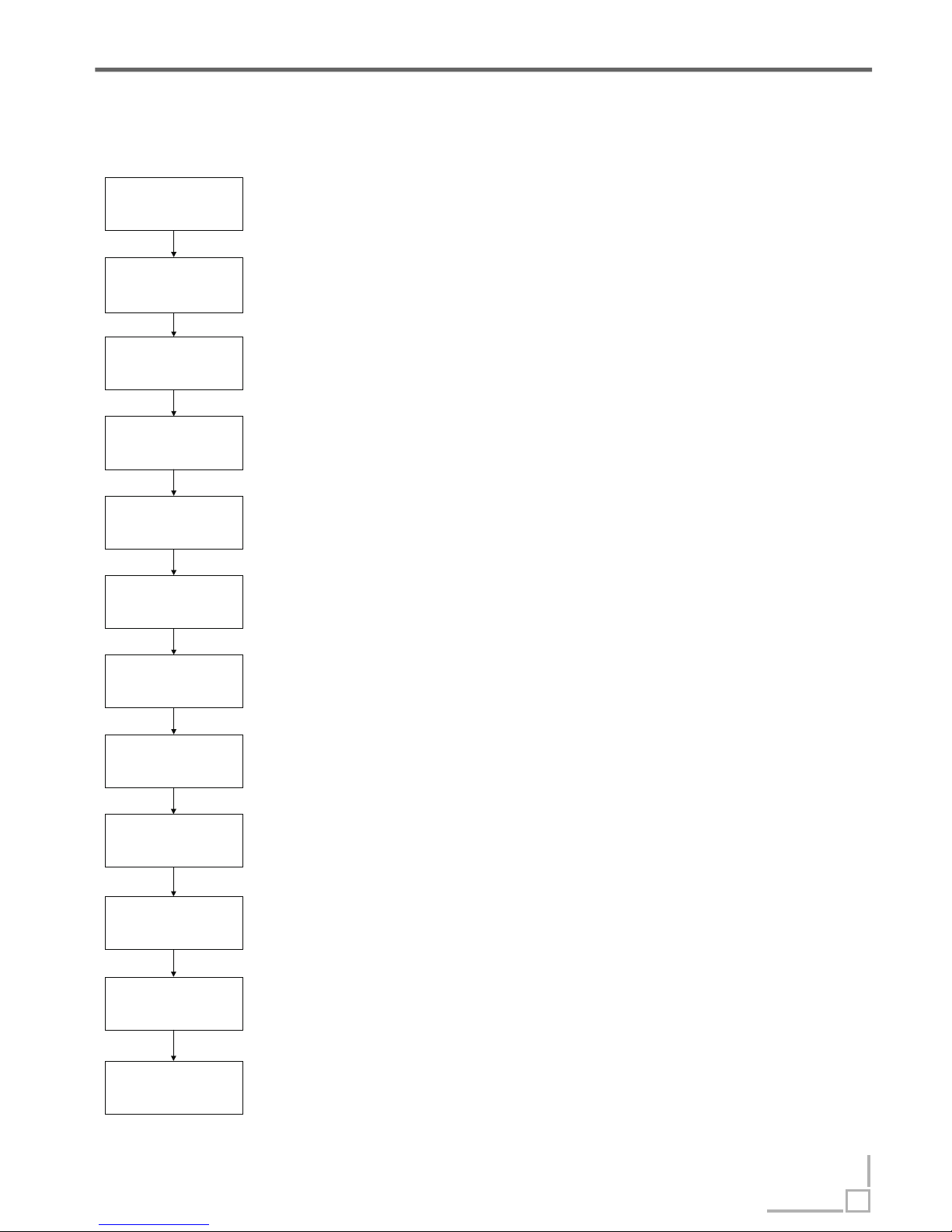
Test Program Procedure
37
00: Power on, standby mode
01: Inlet valve start to work, feeds 3.6 liter water into dishwasher.(45cm
appliance feeds 2.8 liter water)
02: Washing pump and dispenser will be running for 60s.
03: Washing pump and hearting element begin to work, hearting
element will be running until water temperature reaches 60 degree.
Please press program button to entry next step.
04: Make drain pump to be running for 60s.
05: The dishwasher pauses 15s
07: Washing pump will be running for 3 minutes.
06: Activate fan and inlet valve, and feed 3.6liter water into
dishwasher.(45 cm appliance has no fan and feeds 2.8 liter water)
10: Open regeneration valve and activate drain pump, drain pump will be
running for 60s.
11: Buzz one sound, then machine stops. Stand by again.
Initialization
Inlet valve
Washing pump
And dispenser
Heating element
Drain pump
Pause
Inlet valve
Washing pump
Drain pump and
Regeneration
valve
Finish
Washing pump
Pause
09: Washing pump will be running for 3 minutes.
08: The dishwasher pauses for 5s
Page 39
Error Code Test program->
38
E1 Longer inlet time
E3 Longer heating time
If the inlet valve has been opened for 4 minutes but the water quantity hasn’t reached
the desired value(measure by pluses), E1 will come on.
When E1 happens, the drain pump will run until flowmeter keep motionless for 2
minutes and all the other loads will be cut off immediately. At the same time, the buzzer
will alarm for 30 seconds and “E1" will be shown on the display.
During program running if abnormal inlet water, which inlet during program running
except inlet water process, has be accounted to 2L(number counter will reset after
every inlet water process) E1 will come on too
If controller measured less than 50 pulses, which regenerated by flowmeter , at the
first 45 seconds in water process, E1 would occur.
,
,.
If the heating element has been working for 60 minutes but the water temperature
detected by NTC hasn’t reached desired value. E3 will come on.
When E3 happens, the drain pump will run until flowmeter keep motionless for 2 minutes
and all the other loads will be cut off immediately. At the same time, the buzzer will alarm
for 30 seconds and “ E3" will be shown on the display.
during washing program, if appliance has detected NTC failure after heating
element starting work, the program will jump to next step after heating 10 minutes. If
there is no NTC failure detected and water temperature hasn’t reached the desired value,
the program will jump to next step after heating 20 minutes.
Caution:
E4 Overflow
At any time, if flooding pressure switch act and keep for longer than 2 seconds, the E4 will
com on. When E4 happens, the drain pump will run until flowmeter keep motionless for 2
minutes and all the other loads will be cut off immediately. At the same time, the buzzer will
alarm for 30 seconds and “E4" will be shown on the display.
Page 40
Error Code Test program->
39
In test program, once open-circuit failure of thermistor is detected by controller, The E6 will
come on. When E6 happens, the drain pump will run until flowmeter keep motionless for 2
minutes and all the other loads will be cut off immediately. At the same time, the buzzer will
alarm for 30 seconds and “E6" will be shown on the display.
E6 Open-circuit failure of thermistor
In test program, once short-circuit failure of thermistor is detected by controller, The E7 will
come on. When E7 happens, the drain pump will run until flowmeter keep motionless for 2
minutes and all the other loads will be cut off immediately. At the same time, the buzzer will
alarm for 30 seconds and “E7" will be shown on the display.
E7 Short-circuit failure of thermistor
Priority level of E4 is the highest. E4 operation is valid after other error operations have
done. When E4 operation has done, all the others are invalid.
Once any error operation has done, the appliance will operate as below before power up
drain for 2 minutes and cut off all the other loads Then detect flowmeter cyclically If
flowmeter act repeat above drain process
:
..
,.
Caution:
Page 41
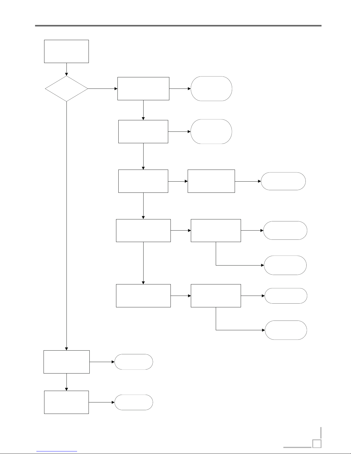
E1 tree Inspection->
If the problem has not been solved through all
the inspection mentioned above, maybe the
PCB has a malfunction. So, replace PCB and
test again.
E1 code
Longer inlet time
Make a check of Tap
No water
Not open
Open it to solve the
problem
Opened
Check whether the Inlet
Valve circuit is correct or
not. (mentioned in section
4)
solve the problem
Not
Correct
Make a check of the
Hydraulic pressure.
(0.04-1.0MPa is ok)
Little water
Give advice to
consumer
Lower
Make a check of
Drain Hose
OK
Is there any
water in the Tub?
Reconnect the wire of
Inlet Valve circuit and
check again
OK
Still wrong
Replace the Inlet
Valve to solve
problem
Check whether the
Flowmeter circuit is correct
or not. (mentioned in
section 4)
Make a check of Inlet
Hose
solve the problem
Inlet Hose is blocked or
kinked
OK
Failure Failure
Reconnect the wire of
Flowmeter circuit and
check again
Not
solve the problem
OK
Replace the
Flowmeter to solve
problem
Still wrong
Make a check of inlet
hose of AQUASTOP,
(only for the dishwasher
with AQUASTOP device)
Replace it to solve
the problem
Failure
Hang correctly to
solve the problem
Wrong
40
Page 42
51
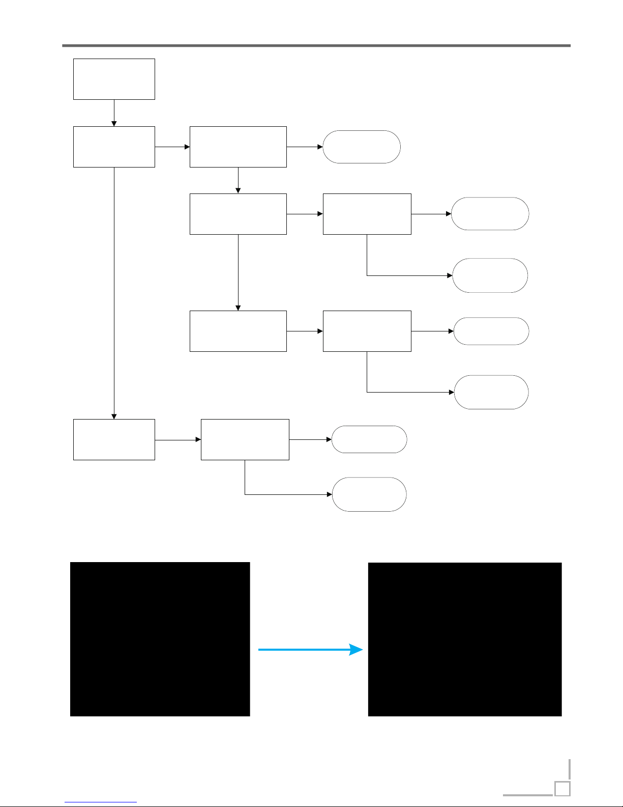
E3 tree Inspection->
If the problem has not been solved through all the inspection mentioned above, maybe the
PCB has a malfunction. So, replace PCB and test again.
Eliminate the influence of Anti-dry-heating Pressure Switch, as above picture, and run the
Test Program to test. If E3 come again, Pressure Switch is normal. If E3 doesn’t come, fault
Pressure switch needs replacement.
E3
Longer heating time
Check water
temperature in the tub
Low
Check whether the
NTC circuit is correct
or not.(mentioned in
section 4)
High
Not
Make a check of Anti-dry-
heating Pressure
Switch.(mentioned below)
Replace Switch to
solve the problem
Failure
OK
Make a check of Heater.
(mentioned in section 4)
Failure
solve the problem
Reconnect the wire of
Heater circuit and check
again
OK
Still wrong
Replace the Inlet
Valve to solve
problem
Check whether the
Washing Pump circuit is
correct or not. (mentioned
in section 4)
Reconnect the wire of
Washing Pump circuit
and check again
Not
solve the problem
OK
Replace the
Washing Pump to
solve problem
Still wrong
OK
Reconnect the wire of
NTC circuit and check
again
solve the problem
OK
Replace the NTC to
solve problem
Still wrong
Eliminate switch’ s
influence
41
Page 43
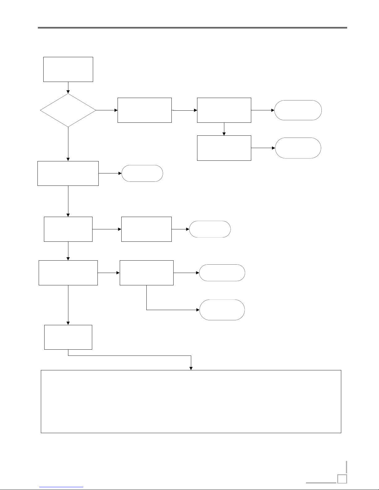
E4 tree Inspection->
E4
Overflow
Is there any water on
the bottom board?
Make a check of
Flooding Switch
circuit(normally closed)
solve the problem
Reconnect the wire of
Flooding Switch circuit
and check again
OK
Still wrong
Repair or Replace it
to solve problem
No water
Check whether Flooding
Switch is blocked or not
Blocked
Failure
Make a check of
Drain Hose
Some
water
Drain Hose is kinked
or blocked
Solve the problem
Failure Failure
OK
Check whether the
Flowmeter circuit is correct
or not. (mentioned in
section 4)
Reconnect the wire of
Flowmeter circuit and
check again
Not
solve the problem
OK
Replace the
Flowmeter to solve
problem
Still wrong
Make sure consumer use
the proper detergent and
rinse
Give advice
OK
Maybe there is a real
leakage
Improper
Correct
Do as follows
Remove baseboard, two side baseboards, top panel and two side panels
Remove the water from the bottom board and make sure there is no water at the bottom board.
Restart the dishwasher with a strong or standard wash program as a leakage could easily repeat at a higher temperature and after a long period
of running time.
Observe the bottom tray every twenty minutes.
If any water appears, you will found out which areas, such as motor, drain pump, sump, softener, and hoses between them, and also clips at the
end of each hose, besides the wel d seam at the bottom of the tub.
If hours passed, but no water c omes out, y ou should stop the dishwasher with sufficient water in the inner tub, and observe it again after leaving
it alone for one to two hours.
42
Page 44
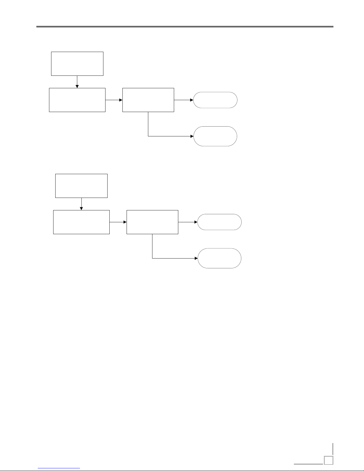
E6&E7 tree Inspection->
E6
Open-circuit failure of
thermistor
Check whether the NTC
circuit is correct or not.
(mentioned in section 4)
Reconnect the wire of
Flowmeter circuit and
check again
Not
solve the problem
OK
Replace the NTC to
solve problem
Still wrong
E7
Short-circuit failure of
thermistor
Check whether the NTC
circuit is correct or not.
(mentioned in section 4)
Reconnect the wire of
Flowmeter circuit and
check again
Not
solve the problem
OK
Replace the NTC to
solve problem
Still wrong
If the problem has not been solved through all the inspection mentioned above, maybe the
PCB has a malfunction. So, replace PCB and test again.
Caution:
Because the real situation is unpredictable, inspection trees mentioned in this manual are
for reference only.
43
 Loading...