

Page 1
PRIER Products, Inc.
4515 East 139th Street
Grandview, MO 64030
(800) 362-9055
Fax (800) 362-1463
Acceptable
4515 East 139th Street
Grandview, MO 64030
(800) 362-9055
Fax (800) 362-1463
Recommended
Acceptable
Not Recommended
Acceptable
4515 E 139th St.
Grandview, MO 64030
800-362-9055 Fax: 800-362-1463
www.PRIER.com
Installation, Operation & Maintenance Instructions for the
PRIER C-634 Heavy Commercial Wall Hydrant
*Please leave this sheet for the property owner*
Thank you for purchasing the PRIER C-634 Heavy Commercial Wall Hydrant, the nest quality commercial
hydrant available. Your C-634 will provide you years of dependable service with little or no maintenance.
Please note: Your C-634 hydrant has drain holes under the packing nut. After shutoff, the drain holes will allow water to
drain for a few moments to prevent freezing. This is normal and according to design.
Installation:
Installation procedures may vary slightly depending on the seat option purchased and the installation inlet options. The
C-634 wall hydrant is available with the following inlet options:
N 1” MIP x 3/4” FIP
P 1” Male SWT x 3/4” Female SWT
V 3/4” ProPress Ready
*P and V inlets only available with CC length
1. Determine the location for the installation of the hydrant. Ensure there is adequate
work room in the interior of the structure for securing the hydrant to the plumbing
piping. Bore a 1 1/8” diameter hole through the wall in the desired position for the
installation and a 1/4” hole that is 1/2” deep.
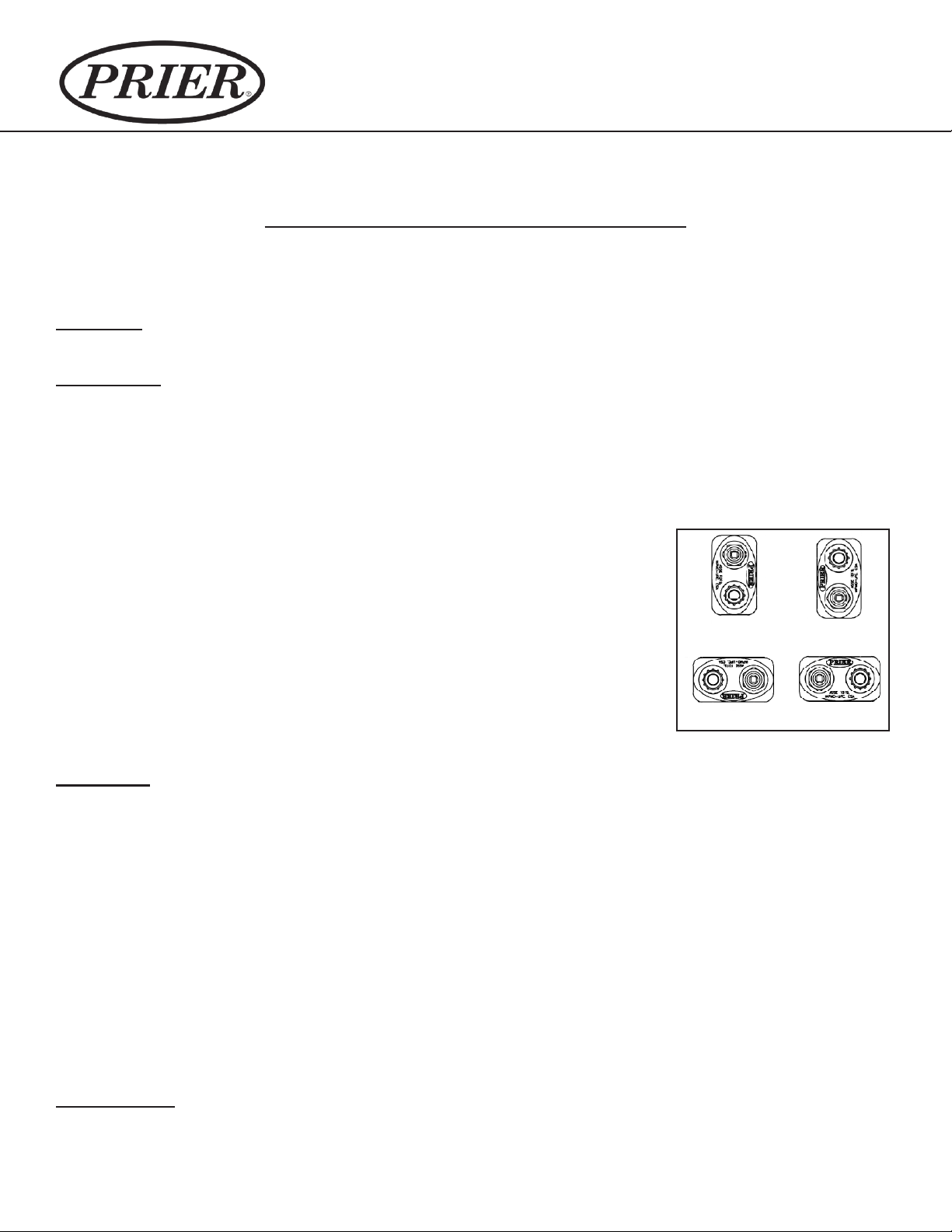
2. The PRIER C-634 is designed for installation in either the horizontal or vertical
position. If using vertical installation, it is recommended that the hydrant be installed
with the hose threads in the “up” position. Refer to the drawings below.
3. If you are planning to solder the connection, be certain the hydrant is in the fully
open position to prevent seat damage from the heat.
4. Connect the water supply piping to the hydrant as desired. With a closed-end hose
on the valve creating back pressure, test the installation for leakage.
5. After the water supply connection is made, secure the hydrant to the structure.
Acceptable
Acceptable
Recommended
Operation:
Operation of the C-634 Commercial Wall Hydrant is a simple process. Water ows through the hydrant after turning the
loose key one full turn counter-clockwise to the “on” position. The hydrant will achieve maximum ow at 2 1/2 full turns.
Turn off the hydrant by turning the loose key clockwise to the “off” position.
The hydrant will drain for a few moments. If the dripping persists after a few moments, tighten the key slightly until the
dripping stops. Be careful not to overtighten the hydrant.
The C-634 incorporates an integral atmospheric anti-siphon vacuum breaker that, in the rare occurrence of a back siphonage, opens to the atmosphere preventing contamination of the water supply.
As well as an atmospheric vacuum breaker, the C-634 incorporates vacuum breaker check valve in the rare case that
water is forced backwards into the valve.
Maintenance:
The C-634 Heavy Commercial Wall Hydrant leaves the factory fully air tested and operational. It is treated with an FDA
approved lubrication. The hydrant requires no scheduled maintenance to provide long life. If the stem is removed, the
bypass O-Ring needs to be replaced and lubricated with an FDA approved lubricant to avoid tearing.
*ALWAYS REMOVE HOSE DURING FREEZING TEMPERATURES*
*INTENDED FOR IRRIGATION USE AND OUTDOOR WATERING*
Page 2
4515 East 139th Street
Grandview, MO 64030
(800) 362-9055
Fax (800) 362-1463
www.PRIER.com
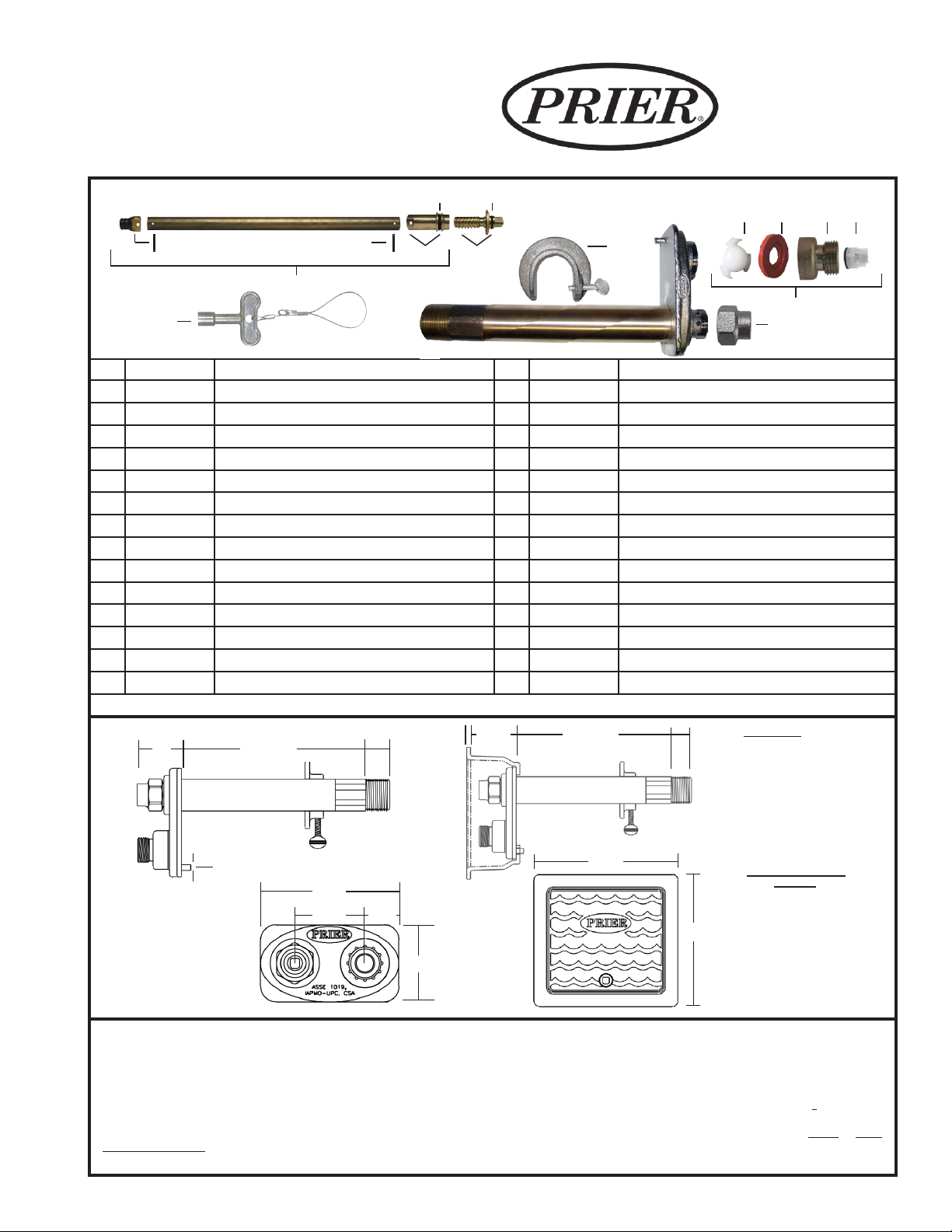
Replacement Parts & Stems
11
12
14
65
15
*When assembling the vacuum breaker, ensure the
dome is facing out on the check spider and the step is
facing out on the silicone washer.
7 8
16
1
13
10
ID Part No. Description ID Part No. Description
1 See Below Stem Assembly, Contains: 5, 14 310-6009 1” Hose Piece for C-636 (NP Brass)
P-231-0604 Stem for 4” C-634 Hydrant, 4 11/16” OAL 5 336-0001 O-Ring Worm Sleeve
P-231-0606 Stem for 6 “ C-634 Hydrant, 6 11/16” OAL 6 336-6001 O-Ring Worm Drive
P-231-0608 Stem for 8” C-634 Hydrant, 8 11/16” OAL 7 337-6001 Check Spider-Vacuum Breaker
P-231-0610 Stem for 10” C-634 Hydrant, 10 11/16” OAL 8 346-6001 Diaphragm-Vacuum Breaker
P-231-0612 Stem for 12” C-634 Hydrant, 12 11/16” OAL 10 C-108KT-808 Loose Key on Lanyard
P-231-0614 Stem for 14” C-634 Hydrant, 14 11/16” OAL 11 C-634KT-802 Stopper Kit, Includes Stopper and Pin
P-231-0616 Stem for 16” C-634 Hydrant, 16 11/16” OAL 12 324-0004 Pin Only
P-231-0618 Stem for 18” C-634 Hydrant, 18 11/16” OAL 13 C-634KT-806 Vacuum Breaker Assembly
P-231-0620 Stem for 20” C-634 Hydrant, 20 11/16” OAL 14 C-634KT-808 Worm Sleeve with O-Ring, Pin and Tool
P-231-0622 Stem for 22” C-634 Hydrant, 22 11/16” OAL 15 C-634KT-809 Worm Drive Assembly with O-Ring
P-231-0624 Stem for 24” C-634 Hydrant, 24 11/16” OAL 16 C-634WCR Wall Clamping Ring
2 300-6003 Valve Stem Cap (NP Brass) 17 399-0001 Secondary Check for ASSE 1052
3 300-6004 3/4” Hose Piece (NP Brass) C-634KT-807 C-634 Overhaul Kit, Contains: 10, 11, 12, 13, 14
**For the old style C-634 Series wall hydrant stems, see C-634 Series retired style spec sheet at www.PRIER.com.
Rough-In Dimensions
2”
(51 mm)
Hydrant Length*
0.25” (6 mm)
4.5”
(114 mm)
2.25”
(55 mm)
1.125”
(28 mm)
0.75”
(19 mm)
(63 mm)
2.50”
0.187”
(5 mm)
2.25”
(57 mm)
Hydrant Length*
6.50”
(165 mm)
0.75”
(19 mm)
6.0”
(152 mm)
Specs
Furnish and install Model C-634 Heavy Commercial Wall Hydrant manufactured by PRIER Products, Inc. Hydrant shall be surface mount and
installed through 1 3/8” round opening. Hydrant shall have automatic draining capabilities with integral vacuum breaker/backow preventor.
Hydrant shall ow 19 gallons per minute minimum at 25 PSI Differential and be at full ow in 2 handle rotations. Hydrant shaft shall be brass
with threaded and sealed connections. Hydrant shall have 3/4” or 1” (choose one) hose connection with freezeless water ow and self-draining
functions, one piece valve plunger, satin nickel nish, brass operating rod with positive triple seal shutoff mechanism. Hydrant shall be approved
under ASSE 1052 standard. Operating key & wall clamping ring to be furnished with each hydrant. Hydrant insertion length to be * inches.
2
Inlet Styles
N Style
3/4” (19 mm) FPT
x 1” (25 mm) NPT
P Style
3/4” (19 mm) Female SWT
x 1” (25 mm) Male SWT
V Style
3/4” (19 mm) ProPress Ready
*Standard Hydrant
Lengths
4” 102 mm
6” 152 mm
8” 203 mm
10” 254 mm
12” 305 mm
14” 356 mm
16” 406 mm
18” 457 mm
20” 508 mm
22” 559 mm
24” 607 mm
3 17
Optional: Furnish and install ush-mount hydrant box for each valve. Hydrant box shall be manufactured of solid cast brass with a brass or satin
nickel plated brass (choose one) nish. Box may be installed separately and hydrant be insertable and removable from front of the box. Access
to the hydrant box shall be provided by the same operating key as the valve. *4” to 24” in 2” increments.
 Loading...