

Page 1

PRIER Products, Inc.
4515 E 139th St.
Grandview, MO 64030
800-362-9055 Fax: 800-362-1463
www.PRIER.com
Installation, Operation & Maintenance Instructions for the
PRIER C-108/208 Diamond Series Hot and Cold Wall Hydrant
*Please leave this sheet for the property homeowner*
Thank you for purchasing the PRIER C-108/208 Diamond Series Hot and Cold Wall Hydrant, the nest quality hot and
cold wall hydrant available. Your C-108/208 will provide you years of dependable service with little or no maintenance.
Installation:
Installation procedures may vary slightly depending on the seat option purchased and the installation inlet options. PRIER
freezeless wall hydrants are available with the following inlet options:
D 1/2” MIP x 1/2” SWT Bore 1” Hole
S 1/2” SWT x 3/4” Push-On Bore 1” Hole
X 1/2” Crimp PEX Bore 1” Hole
W 1/2” Wirsbo® PEX Bore 1” Hole
T 3/4” MIP x 1/2” FIP Bore 1 1/8” Hole
F 3/4” MIP x 3/4” SWT Bore 1 1/8” Hole
FX 3/4” Crimp PEX Bore 1 1/8” Hole
FW 3/4” Wirsbo® PEX Bore 1 1/8” Hole
1. Determine the location for the installation of the hydrant. The valve must be installed into a heated area of the struc-
ture that will not drop below freezing. Ensure there is adequate work room in the interior of the structure for securing
the hydrant to the plumbing piping.
2. The PRIER C-108/208 is designed for installation for either vertical or horizontal application. The hose threads must
be oriented in the DOWN position then locked into place. If the hose thread is not oriented properly, the water will not
be able to drain from the hydrant and freeze damage may occur.
3. Bore 2 holes in the size listed above at 3 1/2” centers through the wall in the desired position for the installation.
4. All freezeless wall hydrants require a slight downward pitch to aid the draining process of the hydrant once the product is turned to the “off” position.
5. Ensure supply piping is free of debris, solder and sealants.
6. If you are planning to solder the connection (D, S or F style seats), be certain the hydrant is in the fully open position
to prevent seat damage from the heat.
7. Connect the water supply piping to the freezeless wall hydrant as desired. With a closed-end hose on the valve creating back pressure, test the installation for leakage.
8. After the water supply connection is made, secure the hydrant to the structure using appropriate screws through the
two mounting holes on the casted back ange.
Operation:
Operation of the C-108/208 Diamond Series Hot and Cold Wall Hydrant is a simple process. Water ows through the
hydrant after turning the handles (or operating key for the C-208 style) counter-clockwise to the “on” position. Turn off the
hydrant by turning the handle clockwise to the “off” position.
The hydrant will drain for a few moments. If the dripping persists after a few moments, tighten the handle slightly until the
dripping stops. Be careful not to overtighten the hydrant.
The C-108/208 incorporates a backow preventer that operates as a check valve in the rare case that water is forced
backwards into the valve. The backow preventer has been tested to 125 PSI pressure.
*ALWAYS REMOVE HOSE DURING FREEZING TEMPERATURES*
*INTENDED FOR IRRIGATION USE AND OUTDOOR WATERING*
Maintenance:
The C-108/208 Diamond Series Hot and Cold Wall Hydrant leaves the factory fully air tested and operational. It is treated
with an FDA approved lubrication. The hydrant requires no scheduled maintenance to provide long life.
Page 2
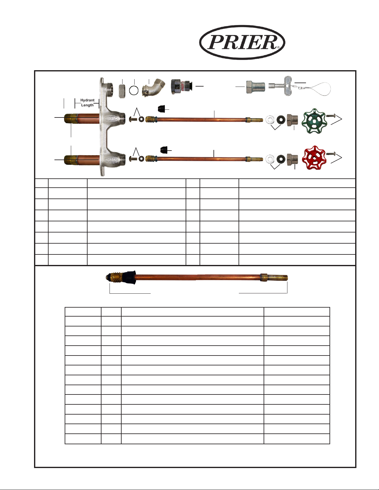
Replacement Parts
Hydrant
3
/4”
Length
4515 East 139th Street
Grandview, MO 64030
(800) 362-9055
Fax (800) 362-1463
www.PRIER.com
10
9
8
7
4
12
13
1
6
3
5
3 1/2” Center-to Center
4
12
1
5
ID Part No. Description ID Part No. Description
1 See Below Stem Assembly, Contains: 1, 4, 12 8 300-0030 Hose Thread Nut
2 300-1008 Valve Stem Cap 9 336-0005 O-Ring for Hose Thread Adapter
3 C-134KT-805 Oval Handle and Screw Kit 10 300-0029 Hose Thread Adapter
4 C-134KT-802 Seat Washer Kit (00 Beveled) 11 C-108KT-805 Red Handle and Screw Kit
5 C-134KT-803 Stem Packing Kit 12 336-0002 Backow Check Valve for C-108
6 C-108KT-808 Loose Key on Lanyard 13 310-1015 Loose Key Valve Stem Cap
7 P-003CP Replacement Vacuum Breaker C-134KT-804 Loose Key Conversion Kit, Contains: 5, 6, 13
Replacement Stems
2
2
Stem Overall Length (OAL)
G Style Manufactured April 2013 - Present
Part No. Style Description Stem Length
P-231-12CC G Close Coupled Stem for C-108 Hydrant 4 3/8" OAL
P-231-1204 G Stem for 4" C-108 Hydrant 6 7/8" OAL
P-231-1206 G Stem for 6 " C-108 Hydrant 8 7/8" OAL
P-231-1208 G Stem for 8" C-108 Hydrant 10 7/8" OAL
P-231-1210 G Stem for 10" C-108 Hydrant 12 7/8" OAL
P-231-1212 G Stem for 12" C-108 Hydrant 14 7/8" OAL
P-231-1214 G Stem for 14" C-108 Hydrant 16 7/8" OAL
P-231-1216 G Stem for 16" C-108 Hydrant 18 7/8" OAL
P-231-1218 G Stem for 18" C-108 Hydrant 20 7/8" OAL
P-231-1220 G Stem for 20" C-108 Hydrant 22 7/8" OAL
P-231-1222 G Stem for 22" C-108 Hydrant 24 7/8" OAL
P-231-1224 G Stem for 24" C-108 Hydrant 26 7/8" OAL
P-231-12US G *Universal Replacement Stem for C-108 Hydrant Up to 16 7/8" OAL
11
**For the old style C-108 Series wall hydrant stems, see C-108 Series retired style spec sheet at www.PRIER.
com. PRIER universal stems are replacement stems for any size from close coupled to 14.” They require cutting
the rod to proper length and soldering the brass stem end to the rod as directed in instructions.
 Loading...