

Page 1

Beforeusingyourairconditioner,pleaseread
thismanualcarefullyandkeepitforfuturereference.
INVERTERSPLITTYPE
-
ROOMAIRCONDITIONER
Pleasereadthisinstallationmanualcompletely
beforeinstallingtheproduct.
Ifthepowercordisdamaged,replacementwork
shallbeperformedbyauthorisedpersonnelonly.
Installationworkmustbeperformedinaccordance
withthenationalwiringStandardsbyauthorised
personnelonly.
Contactanauthorisedservicetechnicianfor
repair,maintenanceorinstallationofthisunit.
PDF created with pdfFactory Pro trial version www.pdffactory.com
Page 2
CONTENTS
SAFETYPRECAUTIONS
Warning...........................................................................................................................................2
Caution............................................................................................................................................2
INSTALLATIONINSTRUCTIONS
Selectinginstallationplace...............................................................................................................3
Accessories.....................................................................................................................................4
Indoorunitinstallation......................................................................................................................5
Outdoorunitinstallation..................................................................................................................7
REFRIGERANTPIPECONNECTION
Refrigerantpipeconnection............................................................................................................8
ELECTRICALWORK
Electricalwork...............................................................................................................................9
Installationofthesolarphotovoltaicsystem.................................................................................12
AIRPURGING
Airpurgingwithvacuumpump......................................................................................................23
Safetyandleakagecheck.............................................................................................................25
TESTRUNNING
Testrunning..................................................................................................................................25
ReadThisManual
Insideyouwillfindmanyhelpfulhintsonhowtoinstallandtesttheairconditionerproperly.
CAUTION
Contactanauthorisedservicetechnicianforrepairormaintenanceofthisunit.
Contactanauthorisedinstallerforinstallationofthisunit.
Theairconditionerisnotintendedforusebyyoungchildrenorinfirmedpersonswithoutsupervision.
Youngchildrenshouldbesupervisedtoensurethattheydonotplaywiththeairconditioner.
Ifthepowercordistobereplaced,replacementworkshallbeperformedbyauthorisedpersonnelonly.
InstallationworkmustbeperformedinaccordancewiththenationalwiringStandardsbyauthorised
personnelonly.
1
PDF created with pdfFactory Pro trial version www.pdffactory.com
Page 3
SAFETYPRECAUTIONS
ReadthefollowSAFETYPRECAUTIONScarefullybeforeinstallation.
Electricalworkmustbeinstalledbyalicensedelectrician.Besuretousethecorrectrating
andmaincircuitforthemodeltobeinstalled.
Incorrectinstallationduetoignoringoftheinstructionwillcauseharmordamage.
Theseriousnessisclassifiedbythefollowingindications.
WARNING
CAUTION
Thissymbolindicatesthepossibilityofdeathorseriousinjury.
Thissymbolindicatesthepossibilityofinjuryordamagetoproperty.
Theitemstobefollowedareclassifiedbythesymbols:
SymbolwithbackgroundwhitedenotesitemthatisPROHIBITEDfromdoing.
WARNING
1)Engagedealerorspecialistforinstallation.Ifinstallationdonebytheuserisdefective,itwillcausewater
leakage,electricalshockfire.
2)Installaccordingtothisinstallationinstructionsstrictly.Ifinstallationisdefective,itwillcausewater
leakage,electricalshockfire.
3)Usetheattachedaccessoriespartsandspecifiedpartsforinstallation.otherwise,itwillcausethesettofall,
waterleakage,electricalshockfire.
4)Installatastrongandfirmlocationwhichisabletowithstandthesetsweight.Ifthestrengthisnotenough
orinstallationisnotproperlydone,thesetwilldropandcauseinjury.
5)Forelectricalwork,followthelocalnationalwiringstandard,regulationandthisinstallationinstructions.An
independentcircuitandsingleoutletmustbeused.Ifelectricalcircuitcapacityisnotenoughordefectfound
inelectricalwork,itwillcauseelectricalshockfire.
6)Usethespecifiedcableandconnecttightlyandclampthecablesothatnoexternalforcewillbeactedon
theterminal.Ifconnectionorfixingisnotperfect,itwillcauseheat-uporfireattheconnection.
7)Wiringroutingmustbeproperlyarrangedsothatcontrolboardcoverisfixedproperly.Ifcontrolboardcover
isnotfixedperfectly,itwillcauseheat-upatconnectionpointofterminal,fireorelectricalshock.
8)Whencarryingoutpipingconnection,takecarenottoletairsubstancesotherthanthespecified
refrigerantgointorefrigerationcycle.Otherwise,itwillcauselowercapacity,abnormalhighpressure
intherefrigerationcycle,explosionandinjury.
9)Donotmodifythelengthofthepowersupplycordoruseofextensioncord,anddonotsharethe
singleoutletwithotherelectricalappliances.Otherwise,itwillcausefireorelectricalshock.
,
CAUTION
1)Thisequipmentmustbeearthedandinstalledwithearthleakagecurrentbreaker.Itmaycauseelectrical
shockifgroundingisnotperfect.
2)Donotinstalltheunitatplacewhereleakageofflammablegasmayoccur.Incasegasleaksand
accumulatesatsurroundingoftheunit,itmaycausefire.
3)Carryoutdrainagepipingasmentionedininstallationinstructions.Ifdrainageisnotperfect,water
mayentertheroomanddamagethefurniture.
2
PDF created with pdfFactory Pro trial version www.pdffactory.com
Page 4
INSTALLATIONINSTRUCTIONS
Selectinginstallationplace
Selectaninstallationlocationwhichisrigidandstrongenoughtosupportorholdtheunit,andselecta
locationforeasymaintenance.Readcompletely,thenfollowstepbystep.
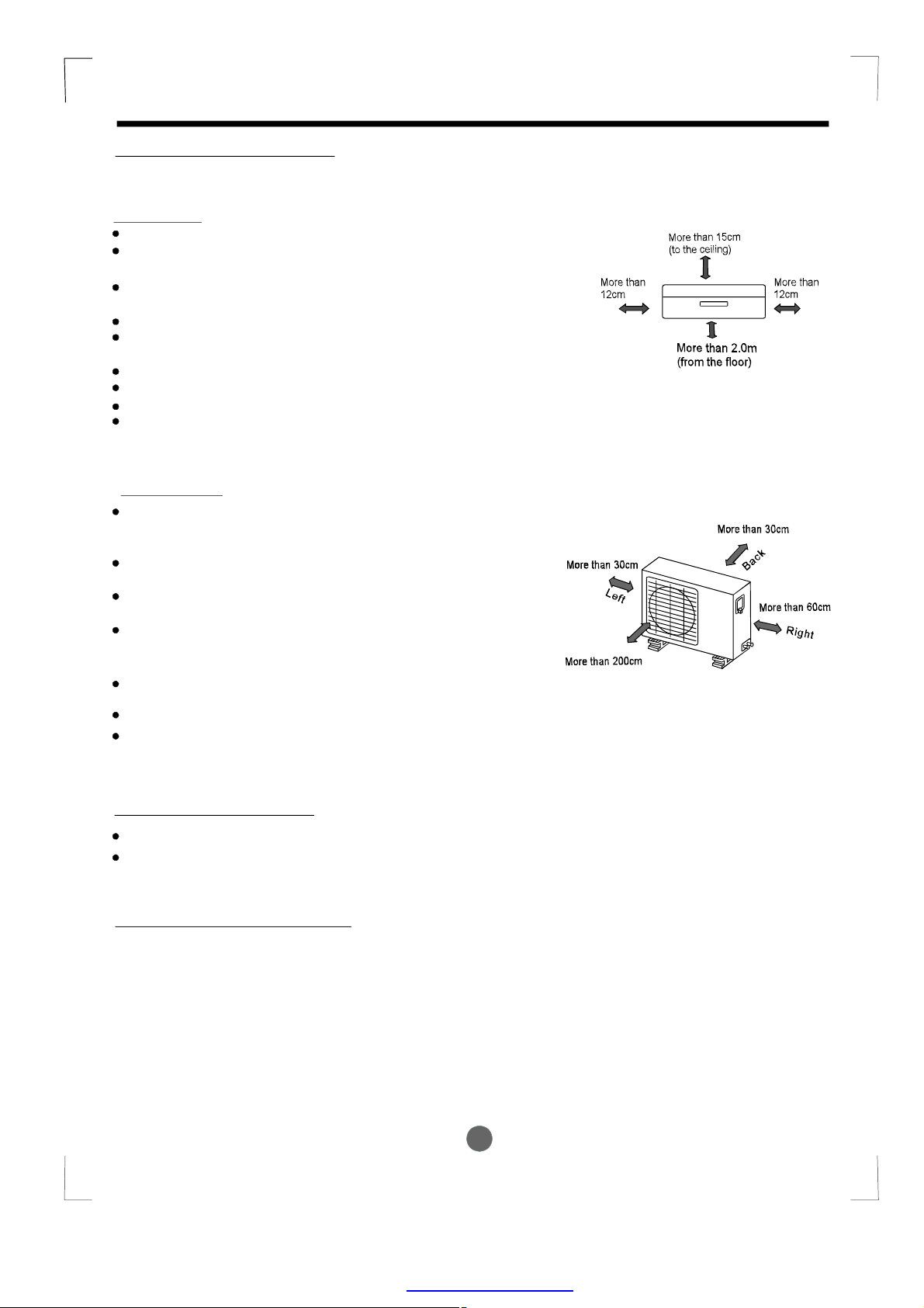
Indoorunit
Donotexposetheindoorunittoheatorsteam.
Selectaplacewheretherearenoobstaclesinfront
oraroundtheunit.
Makesurethatcondensationdrainagecanbe
convenientlyroutedaway.
Donotinstallnearadoorway.
Ensurethespacesindicatedbyarrowsfromthe
wallceilingorotherobstacles.
Aplacewherenoisepreventionistakenintoconsideration.
Aplace1mormoretoTVorradioinstrument.
Aplacewhereaircirculationintheroomisgood.
Thereshouldnotbeanydirectsunlight.Otherwise,thesun
willfadetheplasticcabinetandaffectitsappearance.If
unavoidable,sunlightpreventionshouldbetakenintoconsideration.
Outdoorunit
Ifanawningisbuiltovertheoutdoorunittoprevent
directsunlightorrainexposure,makesurethatheat
radiationfromthecondenserisnotrestricted.
Keepthespacesindicatedbyarrowsfromwallor
otherobstacles.
Donotplaceanimalsandplantsinthepathofthe
airinletoroutlet.
Taketheairconditionerweightintoaccountand
selectaplacewherenoise,vibrationandhotair
dischargedwillnotbeanissue.
Donotinstallinaplacefullofmachineoilorsulfide
gassuchashot-springresort.
Donotinstallinasalineplacesuchascoast.
Donotinstallinaplacewheretherearehighfrequency
machinessuchaswirelessequipment,welding
machineormedicalfacility.
Front
Fig.1
Fig.2
Rooftopinstallation:
Iftheoutdoorunitisinstalledonaroofstructure,besuretoleveltheunit.
Ensuretheroofstructureandanchoringmethodareadequatefortheunitlocation.
Consultlocalcodesregardingrooftopmounting.
Toolsneededforinstallation:
Levelgauge
Screwdriver
Electricdrill,Holecoredrill(65φ mm)
Flaringtoolset
Specifiedtorquewrenches:1.8kgf.m,
4.2kgf.m,5.5kgf.m,6.6kgf.m
(differentdependingonmodelNo.)
Spanner(halfunion)
Hexagonalwrench(4mm)
Gas-leakdetector
Vacuumpump
Gaugemanifold
Usersmanual
Thermometer
Multimeter
Pipecutter
Measuringtape
3
PDF created with pdfFactory Pro trial version www.pdffactory.com
Page 5
INSTALLATIONINSTRUCTIONS
Accessories
Number
1
2
3
4
5
NameofAccessories
InstallationPlate
PlasticExpansionSheath
Self-tappingScrewAST3.9X25
Seal(Forcooling&heatingmodelsonly)
DrainJoint(Forcooling&heatingmodelsonly)
Qty’
1
5-8(dependingonmodels)
5-8(dependingonmodels)
1
1
14
Connecting
6
pipeAssembly
Liquidside
Gasside
38
12
Partsyoumustpurchase.Consult
thetechnicianfortheproper
pipesize.
58
7
8
9
Remotecontroller
Self-tappingScrewBST2.9X10
Remotecontrollerholder
Optional
parts
Note: Excepttheabovepartsprovided,theotherpartsneededduringinstallationyou
mustpurchase.
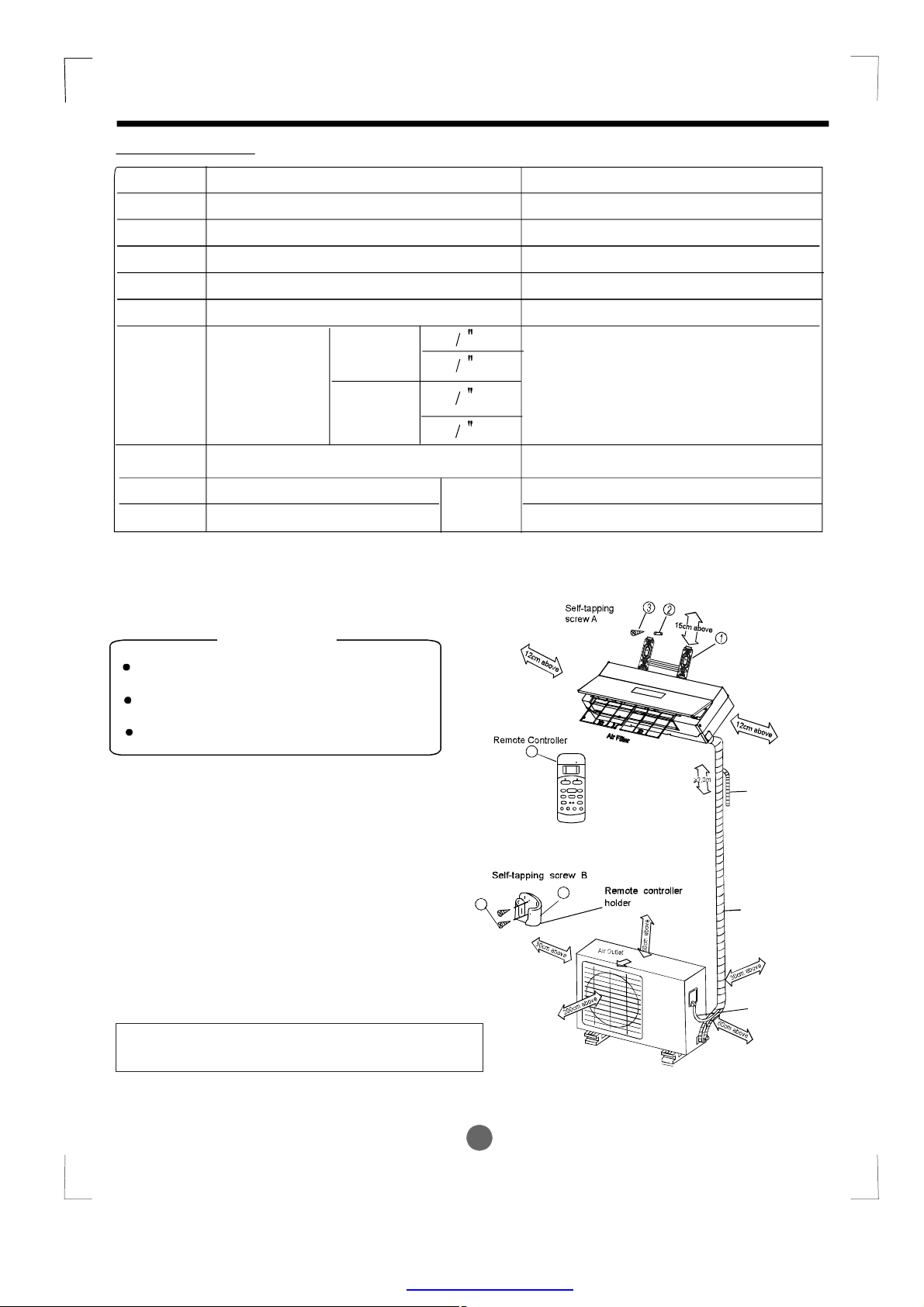
1
2
1
CAUTION
Useastudfindertolocatestudstoprevent
unnecessarydamagetothewall.
Aminimumpiperunof3metresisrequired
tominimisevibration&excessivenoise.
TwooftheA,BandCdirectionsshouldbe
freefromobstructions.
●
Thisillustrationisforexplanationpurposesonly.
●
Copperlinesmustbeinsulatedindependently
7
SETTEMPERATURE(C)
AUTO
FAN
COOL
HIGH
DRY
MED
HEAT
LOW
ADJUST
ON/OFF
MODE
FANSPEED
DIRECTION
/SWING
SLEEP
TIMERON
CLEAN
TIMEROFF
RESETLOCK
AIR
SELF
FOLLOW
LED
TURBO
CLEAN
ME
DISPLAY
8
9
A
B
Additionaldrainpipe
Wrappingtape
Loopthe
connective
cable.
C
.
Fig.3
4
PDF created with pdfFactory Pro trial version www.pdffactory.com
Page 6
INSTALLATIONINSTRUCTIONS
Indoorunitinstallation
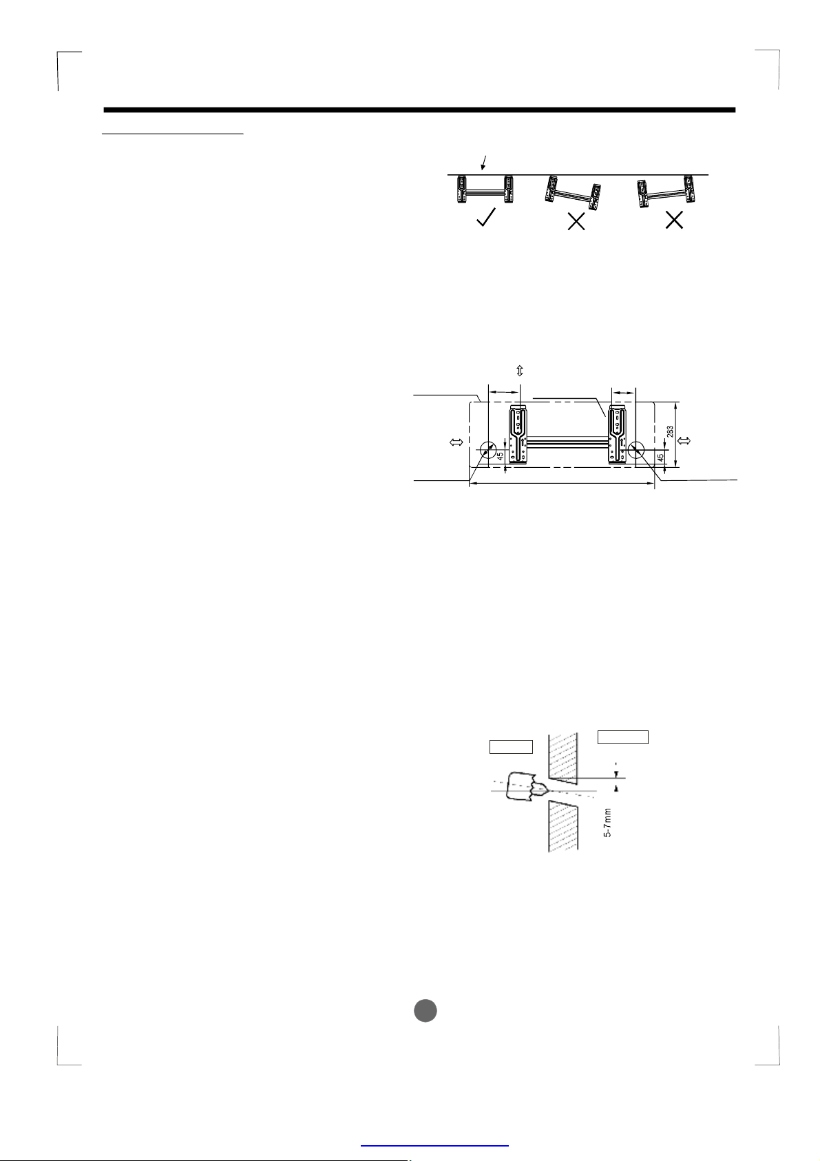
1.FittheInstallationPlate
1.Fittheinstallationplatehorizontally
onstructuralpartsofthewallwith
spacesaroundtheinstallationplate.
2.Ifthewallismadeofbrick,concrete
orthelike,drilleight(8)5mmdiameter
holesinthewall.InsertClipanchorfor
appropriatemountingscrews.
3.Fittheinstallationplateonthewall
witheight(8)type“A” screws.
Note:
FittheInstallationPlateanddrill
holesinthewallaccordingtothe
wallstructureandcorresponding
mountingpointsontheinstallation
plate.Theinstallationplateisdifferent
accordingtothemodels.
(Dimensionsarein“mm” unless
otherwisestated)
Indoorunitoutline
120mmor
moretowall
Leftrearside
refrigerant
pipehole65
φ
Correctorientation
ofInstallationPlate
Fig.4
150mmormoretoceiling
Installationplate
900
Fig.5
90150
120mmor
moretowall
Rightrearside
refrigerant
pipehole65
φ
2.Drillaholeinthewall
1.Determineholepositionsaccording
tothediagramdetailedinFig.5.Drill
one(1)hole(65mm)slantingslightly
φ
tooutdoorside.
2.Alwaysusewallholeconduitwhen
drillingmetalgrid,metalplateorthelike.
Wall
Indoor
Outdoor
Fig.6
5
PDF created with pdfFactory Pro trial version www.pdffactory.com
Page 7
INSTALLATIONINSTRUCTIONS
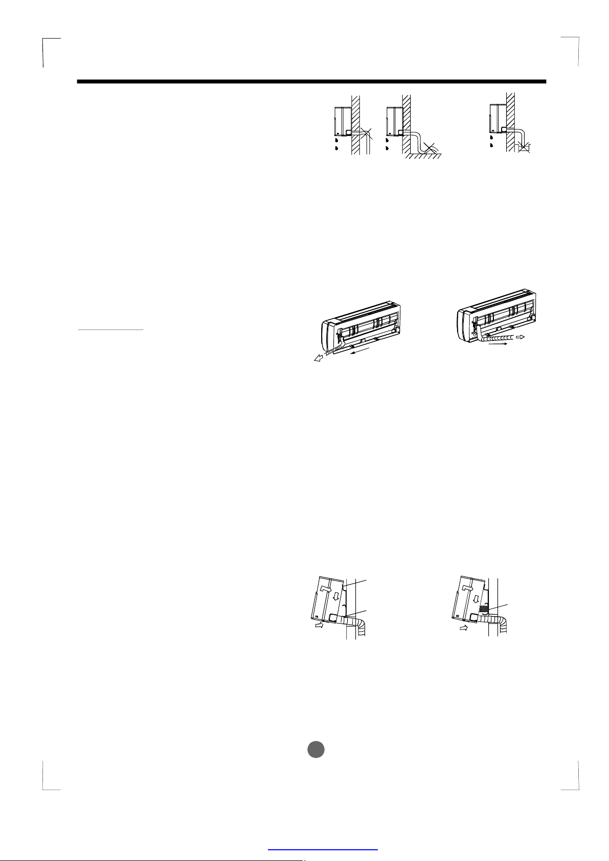
3.ConnectivePipeandDrainage
Installation
Drainage
1.Runthedrainhoseslopingdownward.
Donotinstallthedrainhoseas
illustratedinFig.7.
2.Whenconnectingextensiondrainhose,
insulatetheconnectingpartofextension
drainhosewithashieldpipe,donotlet
thedrainhoseslack.
Connectivepipeinstallation
IMPORTANT:
oftheindoorunit,theunitcanonlyuseRighthandpipingorRightrearpipingasshownin
Fig.8.
1.Removethecoverforright-handpipingfirst.
2.Fortherightrearpiping,installthepipingas
showninFig.8.
3.Fixtheendoftheconnectivepipe.(Refer
toTighteningConnectionin
REFRIGERANTPIPINGCONNECTION)
Forthebottomspacelimitation
Donotblockwaterflowbyarise.
Right-handpiping
Fig.8
Donotputtheendof
drainhoseintowater.
Fig.7
Rightrearpiping
4.Indoorunitinstallation
1.Passthepipingthroughtheholeinthe
wall.
2.Puttheupperclawatthebackofthe
indoorunitontheupperhookofthe
installationplate,movetheindoorunit
fromsidetosidetoseethatitissecurely
hooked(seeFig.9&Fig.10).
3.Pipingcaneasilybemadebyliftingthe
indoorunitwithacushioningmaterial
betweentheindoorunitandthewall.
Getitoutafterfinishpiping.
4.Pushthelowerpartoftheindoorunitup
onthewall,thenmovetheindoorunit
fromsidetoside,upanddowntocheck
ifitishookedsecurely.
UpperHook
Cushioning
LowerHook
Fig.9
Fig.10
material
6
PDF created with pdfFactory Pro trial version www.pdffactory.com
Page 8
5.Pipingandwrapping
Bundlethetubing,connectingcable,anddrain
hosewithtapesecurely,evenlyasshownin
Fig.12
Becausethecondensedwaterfromrearofthe
indoorunitisgatheredinpondingboxandis
pipedoutofroom.Donotputanythingelsein
thebox.
INSTALLATIONINSTRUCTIONS
Indoorunit
Connective
cable
Pondingbox
Piperoom
Drainhose
CAUTION
Connecttheindoorunitfirst,thenthe
outdoorunit.
Donotallowthepipingtoletoutfromthe
backoftheindoorunit.
Becarefulnottoletthedrainhoseslack.
Heatinsulatedbothoftheauxiliarypiping.
Besurethatthedrainhoseislocatedat
thelowestsideofthebundle.Locatingat
theuppersidecancausedrainpanto
overflowinsidetheunit.
Neverintercrossnorintertwistthepower
wirewithanyotherwiring.
Runthedrainhoseslopeddownwardto
drainoutthecondensedwatersmoothly.
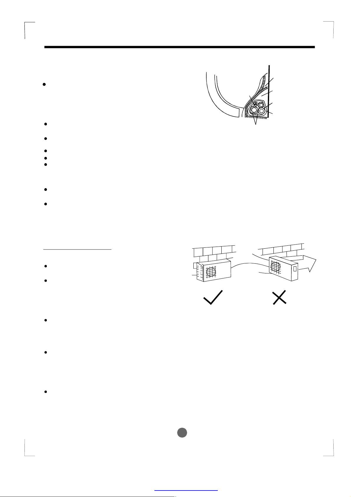
Outdoorunitinstallation
Outdoorinstallationprecaution
Installtheoutdoorunitonarigidbaseto
preventincreasingnoiselevelandvibration.
Determinetheairoutletdirectionwherethe
dischargedairisnotblocked.Inthecasethat
theinstallationplaceisexposedtostrongwind
suchasaseaside,makesurethefanoperating
properlybyputtingtheunitlengthwisealongthe
wallorusingadustorshieldplates.
Speciallyinwindyarea,installtheunittopreventtheadmissionofwind.Ifneedsuspending
installation,theinstallationbracketshould
accordwithtechniquerequirementinthe
installationbracketdiagram.
Theinstallationwallshouldbesolidbrick,
concreteorthesameintensityconstruction,or
actionstoreinforce,dampingsupportingshould
betaken.Theconnectionbetweenbracketand
wall,bracketandtheairconditionershouldbe
firm,stableandreliable.
Besurethereisnoobstaclewhichblock
radiatingair.
Wrappingbelt
Connectivepipe
Fig.11
Strong
wind
Fig.12
7
PDF created with pdfFactory Pro trial version www.pdffactory.com
Page 9
REFRIGERANTPIPECONNECTION
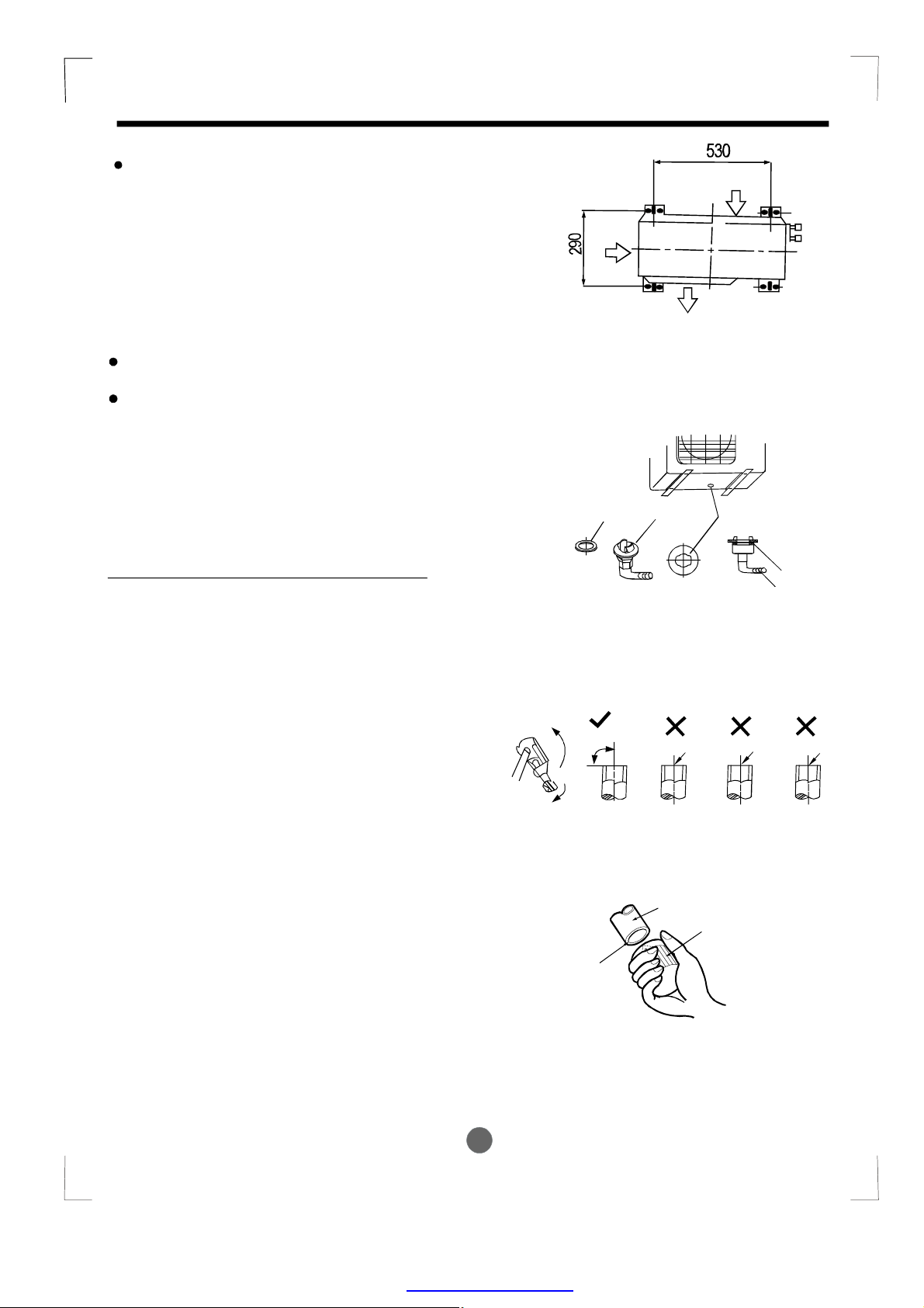
Settlementofoutdoorunit
Anchortheoutdoorunitwithaboltand
nut10or8tightlyandhorizontally
φφ
onaconcreteorrigidmount.
Airinlet
Airinlet
Airoutlet
Drainjointinstallation
Ifadrainelbowisused,theunitshouldbe
placedonastandwhichistallerthan3cm.
Fitthesealintothedrainelbow,theninsert
thedrainjointintothebasepanholeof
outdoorunit,rotate90tosecurelyassemble
。
them.Connectingthedrainjointwithan
extensiondrainhose(Locallypurchased),
incaseofthewaterdrainingofftheoutdoorunit
duringtheheatingmode.
Refrigerantpipeconnection
1.Flaringwork
Maincauseforrefrigerantleakage
isduetodefectintheflaringwork.
Carryoutcorrectflaringwork
usingthefollowingprocedure:
A:Cutthepipesandthecable.
1.Usethepipingkitaccessoryorpipes
purchasedlocally.
2.Measurethedistancebetweentheindoor
andtheoutdoorunit.
3.Cutthepipesalittlelongerthanthe
measureddistance.
4.Cutthecable1.5mlongerthanthepipe
length.
B:Burrremoval
1.Completelyremoveallburrsfromthecut
crosssectionofpipe/tube.
2.Puttheendofthecoppertube/pipeina
downwarddirectionasyouremoveburrsin
ordertoavoiddroppingburrsintothetubing.
Seal
。
90
Pointdown
Fig.13
Drainjoint
Fig.14
Oblique
Fig.15
Pipe
Basepanholeof
outdoorunit
Seal
Drainpipe
Roughness Burr
Reamer
8
PDF created with pdfFactory Pro trial version www.pdffactory.com
Fig.16
Page 10

ELECTRICALWORK
C:Puttingnuton
Removeflarenutsattachedtoindoorand
outdoorunit,thenputthemonpipe/tube
havingcompletedburrremoval.(notpossible
toputthemonafterflaringwork)
D:Flaringwork
Firmlyholdcopperpipeinadieinthe
dimensionshowninthetablebelow.
Max.
A(mm)
Min.
Outerdiam.
(mm)
6.35 1.3 0.7
9.52
12.7
12.7
1.6 1.0
1.8
1.8
1.0
1.0
TighteningConnection
Alignthecenterofthepipes.
Sufficientlytightentheflare
nutwithfingers,andthentighten
itwithaspannerandtorquewrench
asshowninFig.20&21.
Outer
diam.
14
38
12
Tightening
torque(N.cm)
1500
(153kgf.cm)
2500
(255kgf.cm)
3500
(357kgf.cm)
Additionaltightening
torque(N.cm)
1600
(163kgf.cm)
2600
(265kgf.cm)
3600
(367kgf.cm)
Coppertube
Bar
Copperpipe
Flarenut
Fig.17
Handle
Bar
Yoke
Cone
Clamphandle
Indoorunittubing Flarenut Pipings
Redarrowmark
Fig.18
Fig.19
Caution
Excessivetorquecanbreaknut
dependingoninstallationconditions.
Electricalwork
Fig.20
ElectricsafetyregulationsfortheinitialInstallation
1.Ifthereisserioussafetyproblemaboutthepowersupply,thetechniciansshouldrefuse
toinstalltheairconditionerandexplaintotheclientuntiltheproblemissolved.
2.Powervoltageshouldbeintherangeof90%~110%ofratedvoltage.
3.Thecreepageprotectorandmainpowerswitchwitha1.5timescapacityofMax.Current
oftheunitshouldbeinstalledinpowercircuit.
4.Ensuretheairconditionerisgroundedwell.
5.AccordingtotheattachedElectricalConnectionDiagramlocatedonthepaneloftheoutdoor
unittoconnectthewire.
6.Allwiringmustcomplywithlocalandnationalelectricalcodesandbeinstalled
byqualifiedandskilledelectricians.
7.Anindividualbranchcircuitandsinglereceptacleusedonlyforthisairconditionermustbe
available.Seethefollowingtableforsuggestedwiresizesandfusespecifications:
9
PDF created with pdfFactory Pro trial version www.pdffactory.com
Page 11

ELECTRICALWORK
Minimumnorminalcross-sectional
areaofconductors:
Ratedcurrent
ofappliance
(A)
>3and<6
>6and<10
>10and<16
>16and<25
NOTE
:Thecablesizeandthecurrentofthe
fuseorswitcharedeterminedbythemaximum
currentindicatedonthenameplatewhichlocated
onthesidepaneloftheunit.Pleaserefertothe
nameplatebeforeselectingthecable,fuseand
switch.
Connectthecabletotheindoorunit
NOTE:Beforeperforminganyelectrical
work,turnoffthemainpowertothesystem.
1.Thefrontpanelshouldberemovedbefore
connectingthecablebetweeninsideand
outside.
2.Pushthefrontpanelupstraightly,thenopen
ittoanangleof20(Fig.21&22).Totakedown
thefrontpanel,youshouldfirstreleasethetwo
lockleversonthebackofthepanel(Fig.23),
thenliftitupward.
3.Releasethecouplerplugsconnectedwiththe
frontdisplaypanelasshowninFig.24.
4.Aftertakingdownthefrontpanel,
electricalboxcoverbylooseningthescrew
asshowninFig.25.
5.Connectingcablebetweenindoorunitand
outdoorunitshallbeapprovedpolychloroprene
sheathedflexiblecord,typedesignation
H07RN-Forheaviercord.Ensurethecolourof
wiresofoutdoorunitandtheterminalNos.are
thesametotheindoorsrespectively,Fig.27.
6.Wrapthosecablesnotconnectedwithterminals
withinsulationtapes,sothattheywillnottouch
anyelectricalcomponents.Securethecable
ontothecontrolboardwiththecordclamp.
Connectthecouplerplugsconnectedwiththe
frontdisplaypanel.
Nominalcross-sectional
area
2
(mm)
0.75
1
1.5
2.5
O
removethe
,
Coupler
plugs
1 2
Fig.21
Backviewofthefrontpanel
Locklever
Removethe
frontpanel
Fig.22
Fig.23
Fig.24
Removetheelectrical
boxconverbyloosen
thescrew.
Fig.25
10
PDF created with pdfFactory Pro trial version www.pdffactory.com
Page 12

7.Reinstalltheelectricalboxcover,keepthe
whitebandjustunderthegrooveasshownin
Fig.26aandcurvethecableintothegroove.
MakesurethecableconnectedwithLED
displaywindowisfixedbytheelectricalbox
coverafterinstallation,Fig.26b.
ELECTRICALWORK
Groove
Connectthecabletotheoutdoorunit
1.Removetheelectricalcontrolboardcover
fromtheoutdoorunitbylooseningthescrew
asshowninFig.28.
2.Connecttheconnectivecablestothe
terminalsasidentifiedwiththeirrespective
matchednumbersontheterminalblockof
indoorandoutdoorunits,Fig.27.
3.Securethecableontothecontrolboardwith
thecordclamp.
4.Topreventtheingressofwater,fromaloop
oftheconnectivecableasillustratedinthe
installationdiagramofindoorandoutdoor
units.
5.Insulateunusedcords(conductors)with
PVC-tape.Processthemsotheydonot
touchanyelectricalormetalparts.
Cableconnected
withLEDdisplay
window
Terminalsonthe
outdoorunit
L1
Y/G
L1 L2
Topowersupply
Band
Fig.26a
L2
S L1
SL1L2
Terminalsonthe
indoorunit
Fig.27
Fig.26b
CircuitBreaker
L2
Tosolarpanel
Y/G
11
Cover
Screw
Fig.28
PDF created with pdfFactory Pro trial version www.pdffactory.com
Page 13

ELECTRICALWORK
Installationofthesolarphotovoltaicsystem
Thisguidecontainsinformationregardingtheinstallationandsafehandlingofsolarphotovoltaic
module.Allinstructionsshouldbereadandunderstoodbeforeattemptingtoinstall.Ifthereis
anyquestion,pleasecontactoursalesdepartmentforfurtherexplanation.Theinstallershould
conformtoallthesafetyprecautionslistedinthisguidewheninstallingthemodule.Localcodes
shouldalsobefollowedinsuchinstallations.
Thismanualdescribesseveraltypicalsystemsofsolarphotovoltaic,butdoesnotinvolvethe
specificstructuresandinstallationproceduresoftheinstallation.Pleaseconsultthesupplierfor
theinformationofthefollowingassemblys:
a)thespecificationsofthesolarphotovoltaicsystem;
b)cablematerial
c)connectingcomponents
d)bracketandsupport
e)supportingparts.
Beforeinstallingasolarphotovoltaicsystem,theinstallershouldbecomefamiliarwiththe
mechanicalandelectricalrequirementforsuchasystem.Keepthisguideinasafeplacefor
futurereference(careandmaintenance)andincaseofsaleordisposalofthemoduleatthe
endofitsusefullife.
General
Installingsolarphotovoltaticsystemsmayrequirespecializedskillsandknowledge.Installation
shouldbeperformedonlybyqualifiedpersons.
Allmodulescomewithapermanentlyattachedjunctionboxand#12AWGteminatedin
MuticontactPV-KBT4orPV-KST4connectors.Wecanprovidecustomerswithfittedcables
foreaseofinstallation,ifdesired.
Theinstallershouldassumetheriskofallinjurythatmightoccurduringinstallation,including,
withoutlimitation,theriskofelectricshock.
Thesolarphotovoltaticelectricalenergyproductionsystemmustcomplywiththefollowing
tableforsuggestedcurrentandvoltagespecifications:
MaximumPowerVoltage(W)
Optimumoperatingvoltage(Vmp)
Optimumoperatingvoltage(Vmp)
Open-circuitvoltage(Vmp)
Short-circuitcurrent(Vmp)
Maximumpowercurrent(Pmax)
OneindividualmodulemaygenerateDCvoltagesgreaterthan30voltswhenexposedtodirect
sunlight.ContactwithaDCvoltageof30Vormoreispotentiallyhazardous.Electricaljointssuch
asthewireterminalwillcausesparks,burningordeadlyelectricshock.Pleasedonottouchsuch
terminalsdirectlyunderanycircumstances.
<700W
<DC32V
>DC20V
<DC42V
<DC25A
<DC20A
Fig.29
12
PDF created with pdfFactory Pro trial version www.pdffactory.com
Page 14

ELECTRICALWORK
Whendisconnectingwiresfromaphotovoltaicmodulethatisexposedtosunlight,
anelectricarcmayresult.Sucharcsmaycauseburns,combustionandmayotherwisecreate
problems.Therefore,beextremelycareful!
Photovoltaicsolarmodulesconvertlightenergytodirect-currentelectricalenergy.Theyare
designedforoutdooruse.Modulesmaybegroundmounted,mountedonrooftops,vehicles,
orboats.Properdesignofsupportstructuresistheresponsibilityofthesystemdesignerand
installer.Properuseofmountingholesissuggestedinafollowingparagraph.
Donotattempttodiassemblethemodule,anddonotremoveanyattachednameplatesor
components.
Fig.30
Donotapplypaintoradhesivetomoduletopsurface.
Donotusemirrorsorothermagnifierstoartificiallyconcentratesunlightonthemodule.
Fig.31
Wheninstallingthesystem,abidewithalllocal,regionalandnationalstatutoryregulations.
Obtainabuildingpermitwherenecessary.Abidewithanylocalandnationalregulationswhen
mountingonvehiclesorboats.
Safetyprecautionforinstallingasolarphotovoltaicsystem
Wheninstallingthesolarmodulesorrepairingtheairconditioner,ensurethecircuitbreakeronthe
solarpaneloftheoutdoorunitisintheOFFstate(pushtheswitchtoposition).During
normaloperation,thecircuitbreakershouldbeinthestate(pushtheswitchtoposition).
""""
""""
ONON
Fig.32
12
13
OFF
PDF created with pdfFactory Pro trial version www.pdffactory.com
Page 15

ELECTRICALWORK
Solarmodulesproduceelectricalenergywhenlightstrikesontheirfrontsurface.TheDCvoltage
mayexceed30V.Ifmodulesareconnectedinseries,thetotalvoltageisequaltothesumofthe
individualmodulevoltages.Ifmodulesareconnectedinparallel,thetotalcurrentisequaltothe
sumofindividualmodulecurrents.
Fig.33
Keepchildrenwellawayfromthesystemwhiletransportingandinstallingmechanicaland
electricalcomponents.
Fig.34
Completelycoverthemodulewithanopaquematerialduringinstallationtokeepelectricityfrom
beinggenerated.Donottouchthecomponentsortheendoflivewires.However,if
protectionshasbeentakenduringtheoperation
accordingtothelocalsafetyregulations,the
aboverequirementisunnecessary.
appropriate
Fig.35
Donotwearmetallicrings,watchbands,ear,nose,lipringsorothermetallicdeviceswhile
installingortroubleshootingphotovoltaicsystems.
Useonlyinsulatedtoolsthatareapprovedforworkingonelectricalinstallations.
Fig.36
13
14
Fig.37
PDF created with pdfFactory Pro trial version www.pdffactory.com
Page 16

ELECTRICALWORK
Whenperforminginstallationindryconditions,pleaseensurethetoolsusedinthedry.
Fig.38
Abidewiththesafetyregulationsforallothercomponentsusedinthesystem,includingwiring
andcables,connectors,chargingregulators,inverters,storagebatteriesandrechargeable
batteries,etc.
Useonlyequipment,connectors,wiringandsupportframessuitableforuseinasolarelectric
systems.Alwaysusethesametypeofmodulewithinaparticularphotovoltaicsystem.
Themoduleframemustbeproperlygrounded.Thegroundingwiremustbeproperlyfastenedto
themoduleframetoassuregoodelectricalcontact.Usetherecommendedtype,oranequivalent,
connectorforthiswire.
Fig.39
Undermormaloutdoorconditionsthemodulewillproducecurrentandvoltagesthataredifferent
thanthoselistedinthedatesheet.Datasheetvaluesarevaluesexpectedatstandardtest
conditions.Accordingly,duringsystemdesign,valuesofshort-circuitcurrent(Isc)andopencircuitvoltage(Voc)markedonULseriesmodulesshouldbemultipliedbyafactorof1.25
whendeterminingcomponentvoltageratings,conductorampacity,fusesizeandsizeofcontrols
connectedtothemoduleorsystemoutput.
Theholeinthebackofthemoduleframeisusedtodrainthewater,ensurenottobeblocked.
Mechanicalinstallation
1.Selectinginstallationplace
Selectasuitableplaceforinstallationofthemodule.
timeoftheday.
Themoduleshouldbefacingduesouthinnorthernlatitudesandduenorthinsouthern
latitudesforbestpowerproduction.
Fordetailedinformationonthebestelevationtiltanglefortheinstallation,pleaseconsult
withthesolarphotovoltaticsystemsupplier.
Donotusemoduleneartheplacewheretheflammablegasmaybegeneratedorcollected.
Themoduleshouldnotbeshadedatany
15
PDF created with pdfFactory Pro trial version www.pdffactory.com
Page 17

ELECTRICALWORK
Fig.40
2.Selectingthepropersupportframe
Alwaysobservetheinstructionsandsafetyprecautionsincludedwiththesupportframetobe
usedwiththemodule.
Neverattempttodrillholesintheglasssurfaceofthemodule,itwillvoidthewarranty.
Donotdrilladditionalmountingholesintheframeofthemodule,itwillvoidthewarranty.
Fig.41
Modulesmustbesecurelyattachedtothemountingstructureusingfourmountingpointsfor
normalinstallation.Ifadditionalwindorsnowloadsareconsideratedfortheinstallation,additional
mountingpointsarealsoused.
Thesupportframemustbemadeofdurable,corrosion-resistantandUV-resistantmaterial.
Theheatexpansionandcoldcontractionofthesupportframeshouldhavenoaffectiontoits
usageandperformance.
3.Groundmount
Selecttheheightofthemountingsystemtopreventthelowestedgeofthemodulefrombeing
coveredbysnowforalongtimeinwinterinareasthatexperienceheavysnowfalls.Inaddition,
assurethelowestportionofthemoduleisplacedhighenoughsothatitisnotshadedbyplants
ortreesordamagedbysandandstonedrivenbywind.
Fig.42
1416
PDF created with pdfFactory Pro trial version www.pdffactory.com
Page 18

4.Roofmount
ELECTRICALWORK
Wheninstallingamoduleonarooforbuilding,ensurethatitissecurelyfastenedandcannotfall
asaresultofwindorsnowloads.
Fig.43
Provideadequateventilationunderamoduleforcooling(5cmminimumairspacebetweenmodule
andmountingsurface).
Fig.44
Wheninstallingmoduleonaroof,ensurethattheroofconstructionissuitable.Inaddition,any
roofpenetrationrequiredtomountthemodulemustproperlysealedtopreventleaks.
Insomecases,aspecialsupportframemaybenecessary.
Theroofinstallationofsolarmodulesmayaffectthefireproofingofthehouseconstruction,soit
isnecessarytouseanearthgroundfaultcircuitbreaker.Anyunproperinstallationmaycause
accidentalinjuries.
Fig.45
Wheninstallingthemoduleonarooforbuilding,dosoincalmwinds.Installingamoduleduring
strongwindsmaycauseaccidents.
5.Polemount
Wheninstallingamoduleonapole,chooseapoleandmodulemountingstructurethatwill
withstandanticipatedwindsforthearea.Thepolemusthaveasolidfoundation.
Roofmount
Groundmount
Fig.46
Polemount
17
PDF created with pdfFactory Pro trial version www.pdffactory.com
Page 19

ELECTRICALWORK
6.Generalinstallation
Modulemountingmustusethepre-drilledmountingholesintheframe.
Themostcommonmountingisachievedbymountingthemoduleusingthefoursymmetry
pointsclosedtotheinnersideonthemoduleframe.
Ifexcessivewindorsnowloadsareexpected,alleightmountingholesmustbeused.
Ifyouwanttoinstallthemodulewithoutusingthe
consultwiththesupplier.
Donotinstallintherainyweather,itmaycauseinsulationfailureduetomoisture,andthereis
ariskofelectricshock.
Fig.47
Donotattempttoliftthemodulebygraspingthemodulesjunctionboxwhilemoving.
pre-drilledmountingholesintheframe,please
,
Donotstandorsteponmodule.
Fig.48
Fig.49
Donotthrowthemoduleordropanythingonthemodule.
Fig.50
Toavoidgalssbreakage,donotplaceanyheavyobjectsonthemodule.
Donotsetthemoduledownhardonanysurface.
Inappropriatetransportandinstallationmaybreaktheglassofthemodule.
Fig.51
18
PDF created with pdfFactory Pro trial version www.pdffactory.com
Page 20

ELECTRICALWORK
Electricalinstallation
1.Generalinstallation
Donotusemodulesofdifferentconfigurationsinthesamesystem.
Thesolarphotovolaticarrayconsistsofmodulesconnectedinparallel,nomorethan3
modulescanbeusedinparallel.Modulesinparallelcanincreasetheoutputcurrentofthesolar
photovolaticsystem,especiallyforIfmodules
areconnectedinparallel,thetotalvoltagesisequaltothesumofindividualvoltages.
Ifmodulesusedinthesolarphotovolaticsystemarenotthespecifiedbrandofthemanufacturer,
itmustcomplywiththeelectricalrequirement.
ofconnectormustbeselectedtosuitthemaximumsystemshortcircuitcurrent,Otherwisethe
cableandtheconnectorwillbeoverheatedunderlargecurrent.
Modulesconnectedinparallelmustuseadesignatedswitchjunctionbox,pleasecontactthe
supplierforpurchasement.Themaximumcurrentofthesolarphotovoltaicsystemandthe
maximumcurrentandvoltagecapacityofthejointsandconnectivecablesshouldbeconsiderated
duringinstallation.
ConnectionmethodA:Thedistancebetweenthemodulesisclose,noneedtousetheextension
cord(3meters),seeFig.52a.
applicationsrequiringhighcurrents,lowvoltages.
Thecrosssectionareaofcableandthecapacity
Fig.52a
Outdoorunit
wireconnection
19
PDF created with pdfFactory Pro trial version www.pdffactory.com
Page 21

ELECTRICALWORK
ConnectionmethodB:Usinga3mextensioncordduringconnectionifthemodulesaredistant
apart,seeFig.52b.
Outdoorunit
wireconnection
Fig.52b
Ifyouwanttoconnectthephotovoltaicmodulesbyusingthecablespurchasedbyyourself,the
followingrequirementsmustbecomplied:
Cableinstallationshouldcomplywithalllocalregionalandnationalregulations.
Insomecountries,anindividualcircuitbreakerusedbetweenthesolarpanelandair
conditionermustbeinstalled.Soselectancircuitbreakerinaccordancewithlocalregulations,
andtheratedcurrentismorethan30A.
Cableinstallationneedtodistinguishthepositivepoleandnegativepole,reverseconnection
maycausepermanentdamagetotheairconditioner.
Usequalifiedphotovoltaiccablesonly.
ThecablecanresistUVraysandclimateofrapidchange.
Theratedvoltageofthecableismorethan600V.
Thecrosssectionareaofthecabledependsonthemaximumshortcircuitcurrentandthe
lengthofwire.
Beverycarefulwheninstallthecableatextremelylowtemperature.
Recommendedtousethecableofcrosssectionareaof4mmorgreater,andthewireshould
beasshortaspossibletoreducetheenergyconsumption.
Whenthemodulesareconnectedinparallel,cablesmustbesecurelyfastenedonthesupportframe
whichisusedformountingthemodulestoavoidwireslack.
Fig.53
20
PDF created with pdfFactory Pro trial version www.pdffactory.com
Page 22

Donotplacethecableonthesharpedgeofthethings.
Fig.54
Attentiontotheminimumbendingradiusofthewire.
Fig.55
Donotunplugtheconnectorwhenthepowerison.
ELECTRICALWORK
Fig.56
Theprotectingsheathmustbeusedonthecableifthereisapossiblefortheanimalsorchildrens
easytotouchit.
Fig.57
Themanufacturerofthesolarphotovoltaicsystemcansupplycablessuitableforuseinasolar
electricsystems.
21
PDF created with pdfFactory Pro trial version www.pdffactory.com
Page 23

ELECTRICALWORK
Ifyouwanttousetheconnectorpurchasedbyyourself,thefollowingrequirementsmustbecomplied:
Useonlyconnectorspecialdesignedforsolarelectricsystems.
Usetherecommendedorspecifiedtoolswheninstalltheconnectors.
Donotunplugtheconnectorswhenthepowerison.
Theconnectorsuitableforthesolarphotovoltaicsystemcanobtainfromthemanufacturer.
Electricalconnection:
Completelycoverthemodulewithanopaquematerialduringmechanicalinstallationandelectrical
installation.
Protectthecablesfrombeingdamaged.
Groundmountingmustabidewithalllocalregulations.
Storagebatterycannotbeconnectedwiththesolarphotovoltaicsystem.
Grounding:
Themoduleframemustbeproperlygrounded.Thegroundingwiremustbeproperlyfastenedto
themoduleframetoassuregoodelectricalcontact.
Ifthesupportframeismadeofmetal,thesurfaceoftheframemustbeelectroplatedandhave
excellentconductivity.Thegroundingwiremustbeproperlyfastenedtothesupportframe.
Therearetwopre-drilledmountingholesintheframe,usedtoinstallthegroundingcable.Each
moduleshouldconnectwiththegroundingcable.
Werecommendtheclosedlugwhengrounding.Firstinsertthegroundcableintothejackofthe
closedlugandweld,theninsertthestainlesssteelbolt(M3)intothetabofthelug,thegrounding
holeontheframeandfinallyanuttosecuretheentireassembly.Thespringwasherisrequiredin
ordertopreventscrewlooseningandcauseimpropergrounding.
Thegroundingresistancemustbelessthan10ohms.
Fig.58
Junctionboxinstallation:
Allmodulescomewithapermanentlyattachedjunctionboxandprovidewithfittedcables.
Thejunctionboxdonotneedthecustomertoinstall,pleasecontactthemanufacturerifthereis
anyproblemwiththemodule.
Disclaimerofliability
Becausetheuseofthismanualandtheconditionsormethodsofinstallation,operation,use
andmaintenanceofphotovoltaic(PV)productarebeyondourcontrol,wedonottakeany
reponsibilityandexpresslydisclaimsliabilityforloss,damage,orexpensearisingoutoforin
anywayconnectedwithsuchinstallation,operation,useormaintenance.Noresposibilityis
assumedbyusforanyinfringementofpatentsorotherrightsofthirdparties,whichmayresulted
byusingthePVproduct.Nolicenseisgrantedbymodificationorotherwiseunderanypatentor
patentrights.Theinformationinthismanualisbasedoncompanysknowledgeandexperience
andisbelievedtobereliable;butsuchinformationincludingproductspecification(without
limitations)andsuggestionsdonotconstituteawarranty,expressedorimplied.Wereserves
therighttochangethemanual,thePVproduct,thespecifications,orproductdatasheets
withoutpriornotice.
,
22
PDF created with pdfFactory Pro trial version www.pdffactory.com
Page 24

AIRPURGING
Aftercomplyingtotheaboveconditions,preparethewiringasfollows:
1)Neverfailtohaveanindividualpowercircuitspecificallyfortheairconditioner.Asforthe
methodofwiring,beguidedbythecircuitdiagrampostedontheinsideofcontrolcover.
2)Thescrewwhichfastenthewiringintheelectricalfittingcaseareliabletocomeloose
fromvibrationswhichtheunitissubjectedduringthecouseoftransportation.Check
themandmakesurethattheyarealltightlyfastened.(Iftheyareloose,itcouldcause
burn-outofthewires.)
3)Specificatioofpowersource.
4)Confirmthatelectricalcapacityissufficient.
5)Checkthestartingvoltageismaintainedatmorethan90percentoftheratedvoltage
markedonthenameplate.
6)Confirmthatthecablethicknessisasspecifiedinthepowersourcespecification.
7)Alwaysinstallanearthleakagecircuitbreakerinawetormoistarea.
8)Thefollowingwouldbecausedbyvoltagedrop:
Vibrationofamagneticswitch,whichwilldamagethecontactpoint,fusebreaking,
disturbanceofthenormalfunctionoftheoverload.
9)Themeansfordisconnectionfromapowersupplyshallbeincorporatedinthefixed
wiringandhaveanairgapcontactseparationofatleast3mmineachactive(phase)
conductors.
Airpurging
Airandmoistureintherefrigerantsystemhaveundesirableeffectsasindicatedbelow:
Pressureinthesystemrises.
●
Operatingcurrentrises.
●
Coolingorheatingefficiencydrops.
●
Moistureintherefrigerantcircuitmayfreezeandblockcapillarytubing.
●
Watermayleadtocorrosionofpartsintherefrigerationsystem.
●
Therefore,theindoorunitandtubingbetweentheindoorandoutdoorunitmustbeleaktested
andevacuatedtoremoveanynoncondensablesandmoisturefromthesystem.
Airpurgingwithvacuumpump
●
Preparation
Checkthateachtube(bothliquidandgassidetubes)betweentheindoorandoutdoorunits
havebeenproperlyconnectedandallwiringforthetestrunhasbeencompleted.Remove
theservicevalvecapsfromboththegasandtheliquidsideontheoutdoorunit.Notethat
boththeliquidandthegassideservicevalvesontheoutdoorunitarekeptclosedatthis
stage.
●
Pipelengthandrefrigerantamount:
Connective
pipelength
Lessthan5m
Morethan5m
Airpurging
method
Usevacuum
pump.
Usevacuum
pump.
Additionalamountofrefrigeranttobecharged
R22:(Pipelength-5)x30g/m
R410A:(Pipelength-5)x20g/m
23
PDF created with pdfFactory Pro trial version www.pdffactory.com
Page 25

AIRPURGING
Whenrelocatetheunittoanotherplace,
performevacuationusingvacuumpump.
Makesuretherefrigerantaddedintotheair
conditionerisliquidforminanycase.
(NotapplicabletotheunitsadoptfreonR22)
Cautioninhandlingthepackedvalve
Openthevalvestemuntilithitsagainstthe
stopper.Donottrytoopenitfurther.
Securelytightenthevalvestemcapwitha
spannerorthelike.
Valvestemcaptighteningtorque(See
Tighteningtorquetableinpreviouspage).
WhenUsingtheVacuumPump
Refrigerant
Outdoor
unit
Packedvalve Halfunion
A
B
Gasside
Liquidside
Fig.59
Indoor
unit
C
D
Flarenut
Stopper
Cap
(Formethodofusingamanifoldvalve,refer
toitsoperationmanual.)
1.Completelytightentheflarenuts,A,B,C,D,
connectthemanifold
valvechargehosetoa
chargeportofthelow-pressurevalveonthe
gaspipeside.
2.Connectthechargehoseconnectiontothe
vacuumpump.
3.FullyopenthehandleLoofthemanifoldvalve.
4.Operatethevacuumpumptoevacuate.After
startingevacuation,
oftheLovalveonthegaspipeside
slightlyloosetheflarenut
and
checkthattheairisentering(Operationnoise
ofthevacuum
commeterindicates0insteadofminus)
pound
pumpchangesanda
5.Aftertheevacuationiscomplete,fullyclose
thehandleLoofthe
manifoldvalveandstop
theoperationofthevacuumpump.Make
evacuationfor15minutesormore
thatthe
-76cmHg(-1x10Pa).
6.TurnthestemofthepackedvalveBabout
45counterclockwisefor6~7secondsafter
compoundmeterindicates
o
5
andcheck
thegascomingout,thentightentheflarenut
again.Makesurethepressuredisplayinthe
pressureindicatorisalittlehigherthanthe
atmospherepressure.
7.RemovethechargehosefromtheLow
pressurechargehose.
8.FullyopenthepackedvalvestemsBandA.
9.Securelytightenthecapofthepackedvalve.
Valvebody
Manifoldvalve
Compoundmeter
-76cmHg
HandleLo
Chargehose
Lowpressurevalve
Valvestem
Fig.60
Pressuregauge
HandleHi
Chargehose
Vacuumpump
Fig.61
24
PDF created with pdfFactory Pro trial version www.pdffactory.com
Page 26

TESTRUNNING
Safetyandleakagecheck
Electricalsafetycheck●
Performtheelectricsafecheckaftercompletinginstallation:
1.Groundingwork
Afterfinishinggroundingwork,measurethegroundingresistancebyvisualdetectionand
groundingresistancetester.Makesurethegroundingresistanceislessthan4.
2.Electricalleakagecheck(performingduringtestrunning)
Duringtestoperationafterfinishinginstallation,theservicemancanusetheelectroprobe
andmultimetertoperformtheelectricalleakagecheck.Turnofftheunitimmediatelyif
leakagehappens.Checkandfindoutthesolutionwaystilltheunitoperateproperly.
Gasleakcheck●
1.Soapwatermethod:
Applyasoapwateroraliquidneutraldetergent
ontheindoorunitconnectionoroutdoorunit
connectionsbyasoftbrushtocheckforleakage
oftheconnectingpointsofthpiping.Ifbubbles
comeout,thepipeshaveleakage.
Leakdetector
2.
Usetheleakdetectortocheckforleakage.
CAUTION
Indoorunit
checkpoint
Cover
Outdoorunit
checkpoint
Ω
DBC
A
A:LopackedvalveB:Hipackedvalve
CandDareendsofindoorunitconnection.
Fig.62
Testrunning
Performtestoperationaftercompletinggasleakcheckattheflarenutconnectionsand
electricalsafetycheck.
Checkthatalltubingandwiringhavebeenproperlyconnected.
Checkthatthegasandliquidsideservicevalvesarefullyopen.
1.Connectthepower,presstheON/OFFbuttonontheremotecontrollertoturntheuniton.
2.UsetheMODEbuttontoselectCOOL,HEAT,AUTOandFANtocheckifallthefunctions
workwell.
3.Whentheamienttemperatureistoolow(lowerthan17C),theunitcannotbecontrolledby
theremotecontrollertorunatcoolingmode,manualoperationcanbetaken.Manual
operationisusedonlywhentheremotecontrollerisdisableormaintenancenecessary.
PresstheManualcontrolbuttonontherightsideofthepanelframetoselecttheAUTOor
COOL,theunitwilloperateunderForcedAUTOorCOOLmode(seeUserManualfordetails).
4.Thetestoperationshouldlastabout30minutes.
Manualcontrol
button
25
PDF created with pdfFactory Pro trial version www.pdffactory.com
Page 27

Thedesignandspecificationsaresubjecttochangewithoutpriornoticeforproduct
improvement.Consultwiththesalesagencyormanufacturerfordetails.
CS0100I-SP(L)
202000192406
PDF created with pdfFactory Pro trial version www.pdffactory.com
 Loading...