

Pridiom PWS247EL Installation Manual
Before using your air conditioner, please read
this manual carefully and keep it for future reference.
INVERTER SPLIT TYPE
-
ROOM AIR CONDITIONER
The design and specifications are subject to change without prior notice for
product improvement. Consult with the sales agency or manufacturer for details.
CS290I-BP11P(USHL)
202000192649
20140320
Please read this installation manual completely
before installing the product.
If the power cord is damaged, replacement work
shall be performed by authorised personnel only.
Installation work must be performed in accordance
with the national wiring Standards by authorised
personnel only.
Contact an authorised service technician for
repair, maintenance or installation of this unit.
CONTENTS
SAFETY PRECAUTIONS
Warning .....................................................................................................................................2
Caution ......................................................................................................................................2
INSTALLATION INSTRUCTIONS
Selecting installation place.........................................................................................................3
Accessories ........ .....................................................................................................................4
Indoor & outdoor unit installation drawings ...............................................................................4
INDOOR UNIT INSTALLATION
Installation plate mounting..........................................................................................................5
Drill a hole in the wall ........ ......................................................................................................6
Connect the cable to the indoor unit..........................................................................................6
Connective pipe and drainage installation..................................................................................7
OUTDOOR UNIT INSTALLAITON
Outdoor installation precaution ..............................................................................................9
Settlement of outdoor unit .......................................................................................................10
Drain joint installation ..............................................................................................................10
Refrigerant pipe connection ....................................................................................................10
Connect the cable to the outdoor unit ...................................................................................12
Air purging.................................................................................................................................12
TEST RUNNING
Test running ...................... .....................................................................................................14
CAUTION
Contact an authorised service technician for repair or maintenance of this unit.
The appliance shall be installed in accordance with national wiring regulations.
This appliance is not intended for use by persons(including children) with reduced
physical, sensory or mental capabilities, or lack of experience and knowledge, unless
they have been given supervision or instruction concerning use of the appliance by a
person responsible for their safety.
Young children should be supervised to ensure that they do not play with the air conditioner.
Do not operate your air conditioner in a wet room such as a bathroom or laundry room.
Installation must be performed in accordance with the requirement of NEC and CEC by
authorized personnel only.
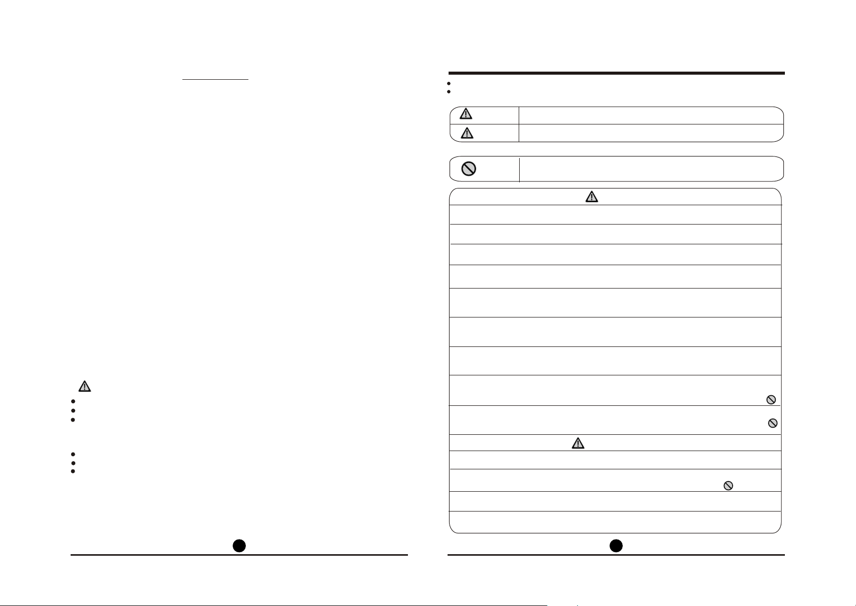
SAFETY PRECAUTIONS
Read the follow SAFETY PRECAUTIONS carefully before installation.
Incorrect installation due to ignoring of the instruction will cause harm or damage, and the
seriousness is classified by the following indications.
WARNING
CAUTION
This symbol indicates the possibility of death or serious injury.
This symbol indicates the possibility of injury or damage to property.
The items to be followed are classified by the symbols:
Symbol will background white denotes item that is PROHIBITED from doing.
WARNING
1) Engage dealer or specialist for installation. If installation done by the user is defective, it will
cause water leakage, electrical shock or fire.
2) Install according to this installation instructions strictly. If installation is defective, it will cause
water leakage, electrical shock or fire.
3) Use the attached accessories parts and specified parts for installation. otherwise, it will cause
the set to fall, water leakage, electrical shock or fire.
4) Install at a strong and firm location which is able to withstand the set s weight. If the strength is
not enough or installation is not properly done, the set will drop and cause injury.
5) For electrical work, follow the local national wiring standard, regulation and this installation
instructions. An independent circuit and single outlet must be used. If electrical circuit capacity
is not enough or defect found in electrical work, it will cause electrical shock or fire.
6) Use the specified cable and connect tightly and clamp the cable so that no external force will
be acted on the terminal. If connection or fixing is not perfect, it will cause heat-up or fire at the
connection.
7) Wiring routing must be properly arranged so that control board cover is fixed properly. If
control board cover is not fixed perfectly, it will cause heat-up at connection point of terminal,
fire or electrical shock.
8) When carrying out piping connection, take care not to let air substances other than the specified
refrigerant go into refrigeration cycle. Otherwise, it will cause lower capacity, abnormal high
pressure in the refrigeration cycle, explosion and injury.
9) Do not modify the length of the power supply cord or use of extension cord, and do not share
the single outlet with other electrical appliances. Otherwise, it will cause fire or electrical
shock.
,
CAUTION
1) This equipment must be earthed and installed with earth leakage current breaker. It may cause
electrical shock if grounding is not perfect.
2) Do not install the unit at place where leakage of flammable gas may occur. In case gas leaks
and accumulates at surrounding of the unit, it may cause fire.
3) Carry out drainage piping as mentioned in installation instructions. If drainage is not perfect,
water may enter the room and damage the furniture.
4) For the unit adopts auxiliary electric heater, keep at least 1 meter away from the nearest
combustible materials.
11 22
INSTALLATION INSTRUCTIONS INSTALLATION INSTRUCTIONS
Selecting installation place
Read completely, then follow step by step.
Indoor unit
There should not be any heat source, inflammable gas or stream near the unit.
There should not be any obstacles blocking the air circulation.
A place where air circulation in the room is good.
A place where drainage can be easily done.
A place where noise prevention is taken into consideration.
Do not install the unit near the door way.
Ensure the restrictions on installation specified in the indoor unit installation drawings are met.
Select a location which is firm enough for installation so that the device is not subjected to
vibrations.
The device should beinstalled at a distance of at least 1m from all other electrical devices and
installations, e.g. TV, radio,computer, etc.
There should not be any direct sunlight. If unavoidable, sunlight prevention should be taken
into consideration.
Outdoor unit
If an awning is built over the unit to prevent direct sunsight or rain,be careful that heat
radiation from the condenser is not obstructed.
There should not be any animal or plant which could be affected by hot air discharged.
Make sure that there is sufficient space as specified in the installation drawings.
Do not place any obstacles which may cause a short circuit of the discharged air.
Select a location which avoids causing a nuisance to neighbours from noise and air emissions
from device.
Select a location which is sufficiently well ventilated.
Never cover the air inlets and outlets.
The location must be sufficiently firm for installation and the prevention of vibrations.
There must be no risk presented by combustible gas or gas escaping as a result of corrosion.
Avoid a location where there is a high salt content.
Avoid a location which is heavily exposed to dust.
Avoid a location to which the general public have access.
Tools needed for installation:
Level gauge
Screwdriver
Electric drill,Hole core drill ( 65mm)
Flaring tool set
Specified torque wrenches: 1.8kgf.m,
4.2kgf.m, 5.5kgf.m, 6.6kgf.m
(different depending on model No.)
Spanner (half union)
Hexagonal wrench (4mm-6mm)
Gas-leak detector
Vacuum pump
Gauge manifold
Users manual
Thermometer
Multimeter
Pipe cutter
Measuring tape
Accessories
Number
1
2
3
4
5
6
Name of Accessories
Installation Plate
Clip Anchor
Self-tapping Screw A ST3.9x25
Seal(For cooling & heating models only)
Drain Joint(For cooling & heating models only
Connecting
pipe
Assembly
Liquid side
Gas side
6.35
9.52
9.52
12.7
Qty
1
5-8(depending on models)
5-8(depending on models)
1
1
Parts you must purchase. The
pipe size differ from appliance to
appliance. Consult the technician
for the proper size.
16
7
Remote controller
Self-tapping Screw B ST2.9x10
8
Remote controller holder
9
Air freshening filter(used to install on Air filter)
10
Except the above parts provided,the other parts needed during installation you must
NOTE:
optional
parts
1
2
1
1
purchase.
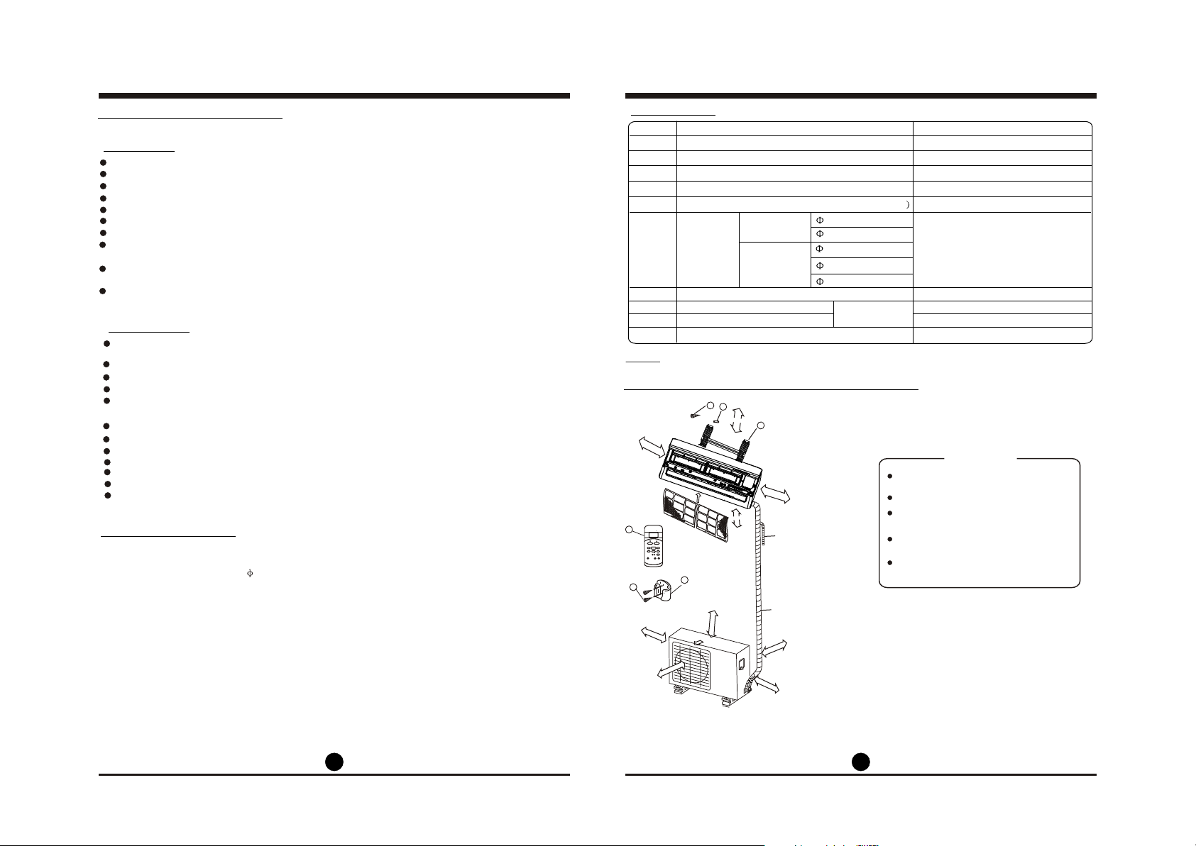
Indoor & outdoor unit installation drawings
3
2
12cm
15cm or more
or mote
The mounting plate should be installed on a wall
1
which can support the weight of the indoor unit.
CAUTION
Air Fi
lter
lterAir Fi
(C)
SET TEMPERATURE
7
FAN
AUTO
HIGH
COOL
MED
DRY
LOW
HEAT
TEMP
ON/OFF
MODE
FAN SPEED
SWING
TIMER ON
SLEEP
TIMER OFF
RESET LOCK
AIR
LED
DIRECTION
DISPLAY
TURBO
30cm or
B
more
200cm or more
9
Air Outlet
r more
o
cm
0
6
8
A
12cm or more
2.3m or more
Additional drain pipe
Wrapping tape(wrap the insulation pipe
with the tape form bottom to top)
30cm or more
60cm o
r more
C
Use a stud finder to locate studs to
prevent unnecessary damage to the
wall.
Two of the A, B and C directions
should be free from obstructions.
This illustration is for explanation
purposes only.
Copper lines must be insulated
independently
Fig.1
33
44
 Loading...