

Pridiom Concealed Duct Installation Manual

INSTALLATION MANUAL
Middle Static Pressure Duct Type
Thank you very much for purchasing our air conditioner,
Before using your air conditioner , please read this manual carefully and keep it for future reference.

If used as MULTI unit, please refer to the Installation & operation manuals packed with outdoor unit.
CONTENTS PAGE
SAFETY PRECAUTIONS.......................................................................................1
INSTALLATION INFORMATION........................................................................... 2
ATTACHED FITTINGS.............................................................................................3
INSPECTING AND HANDLING THE UNIT.........................................................4
INDOOR UNIT INSTALLATION.................................................................................4
OUTDOOR UNIT INSTALLATION............................................................................11
INSTALL THE CONNECTING PIPE..................................................................15
REFRIGERANT PIPE..........................................................................................16
REFRIGERANT PIPE CONNECTION ...............................................................17
CONNECTIVE DIAGRAM......................................................................................18
CONNECT THE DRAIN PIPE..............................................................................18
FRESH AIR DUCT INSTALLATION.......................................................................19
CONTROL..............................................................................................20
WIRING.................................................................................................20
TEST OPERATION................................................................................................21
1. SAFETY PRECAUTIONS
Keep this manual where the operator can easily find them.
Read this manual attentively before starting up the units.
For safety reason the operator must read the following
cautions carefully.
Installation must be performed in accordance with the
requirement of NEC and CEC by authorized personnel only.
The safty precautions listed here are divided into two categories.
WARNING
If you do not follow these instrutions exactly, the unit may
cause property damage, personal injury or loss of life.
CAUTION
If you do not follow these instrutions exactly, the unit may
cause minor or moderate property damage, personal
injury.
After completing the installation, make sure that the unit operates
properly during the start-up operation. Please instruct the customers
on how to operate the unit and keep it maintained.Also, inform
customers that they should store this installation manual along with
the owner's manual for future reference.
WARNING
Be sure only trained and qualified service personnel to
install, repair or service the equipment.
Improper installation, repair, and maintenance may result in
electric shocks, short-circuit, leaks, fire or other damage to
the equipment.
Install according to this installation instructions strictly.
If installation is defective, it will cause water leakage,
electrical shock and fire.
When installing the unit in a small room, take measures
against to keep refrigerant concentration from exceeding
allowable safety limits in the event of refrigerant leakage.
Contact the place of purchase for more information.
Excessive refrigerant in a closed ambient can lead to oxygen
deficiency.
Use the attached accessories parts and specified parts
for installation.
otherwise, it will cause the set to fall, water leakage,
electrical shock and fire.
Install at a strong and firm location which is able to
withstand the set' s weight.
If the strength is not enough or installation is not properly
done, the set will drop to cause injury.
The appliance must be installed 2.3m / 7.5ft above floor.
The appliance shall not be installed in the laundry.
Before obtaining access to terminals, all supply circuits
must be disconnected.
The appliance must be positioned so that the plug is
accessible.
The enclosure of the appliance shall be marked by word,
or by symbols, with the direction of the fluid flow.
For electrical work, follow the local national wiring
standard, regulation and this installation instructions. An
independent circuit and single outlet must be used.
If electrical circuit capacity is not enough or defect in
electrical work, it will cause electrical shock or fire.
Use the specified cable and connect tightly and clamp
the cable so that no external force will be acted on the
terminal.
If connection or fixing is not perfect, it will cause heat-up or
fire at the connection.
Wiring routing must be properly arranged so that control
board cover is fixed properly.
If control board cover is not fixed perfectly, it will cause
heat-up at connection point of terminal, fire or electrical
shock.
If the supply cord is damaged, it must be replaced by the
manufacture or its service agent or a similarly qualified
person in order to avoid a hazard.
An all-pole disconnection switch having a contact
separation of at least 3mm/0.118in in all poles should be
connected in fixed wiring.
When carrying out piping connection, take care not to let
air substances go into refrigeration cycle.
Otherwise, it will cause lower capacity, abnormal high
pressure in the refrigeration cycle, explosion and injury.
Do not modify the length of the power supply cord or use
of extension cord, and do not share the single outlet with
other electrical appliances.
Otherwise, it will cause fire or electrical shock.
Carry out the specified installation work after taking into
account strong winds, typhoons or earthquakes.
Improper installation work may result in the equipment falling
and causing accidents.
installation manual
1
If the refrigerant leaks during installation, ventilate the
area immediately.
Toxic gas may be produced if the refrigerant comes into the
place contacting with fire.
The temperature of refrigerant circuit will be high, please
keep the interconnection cable away from the copper
tube.
After completing the installation work, check that the
refrigerant does not leak.
Toxic gas may be produced if the refrigerant leaks into the
room and comes into contact with a source of fire, such as a
fan heater, stove or cooker.
CAUTION
Ground the air conditioner.
Do not connect the ground wire to gas or water pipes,
lightning rod or a telephone ground wire.inappropriate
grounding may result in electric shocks.
Be sure to install an earth leakage breaker.
Failure to install an earth leakage breaker may result in
electric shocks.
Connect the outdoor unit wires , then connect the indoor
unit wires.
You are not allowed to connect the air conditioner with the
power supply until the wiring and piping is done.
While following the instructions in this installation
manual, install drain piping in order to ensure proper
drainage and insulate piping in order to prevent
condensation.
Improper drain piping may result in water leakage and
property damage.
Install the indoor and outdoor units, power supply wiring
and connecting wires should be at least 1 meter away
from televisions or radios in order to prevent image
interference or noise.
Depending on the radio waves, a distance of 1 meter may not
be sufficient enough to eliminate the noise.
The appliance is not intended for use by young children
or infirm persons without supervision.
Don't install the air conditioner in the following
circumstance:
There is petrolatum existing.
There is salty air surrounding (near the coast).
There is caustic gas (the sulfide, for example) existing
in the air (near a hot spring).
The Volt vibrates violently (in the factories).
In buses or cabinets.
In kitchen where it is full of oil gas.
There is strong electromagnetic wave existing.
There are inflammable materials or gas.
There is acid or alkaline liquid evaporating.
Other special conditions.
The appliance shall be installed in accordance with
national wiring regulations.
Do not operate your air conditioner in a wet room such
as a bathroom or laundry room.
An all-pole disconnection device which has at least 3mm
clearances in all poles , and have a leakage current that
may exceed 10mA, the residual current device (RCD)
having a rated residual operating current not exceeding
30mA, and disconnection must be incorporated in the
fixed wiring in accordance with the wiring rules.
2. INSTALLATION INFORMATION
To install properly, please read this "installation manual" at
first.
The air conditioner must be installed by qualified persons.
When installing the indoor unit or its tubing, please follow
this manual as strictly as possible.
If the air conditioner is installed on a metal part of the
building, it must be electrically insulated according to the
relevant standards to electrical appliances.
When all the installation work is finished, please turn on
the power only after a thorough check.
Regret for no further announcement if there is any change
of this manual caused by product improvement.
INSTALLATION ORDER
Select the location;
Install the indoor unit;
Install the outdoor unit;
Install the connecting pipe ;
Connect the drain pipe;
Wiring;
Test operation.
installation manual
2
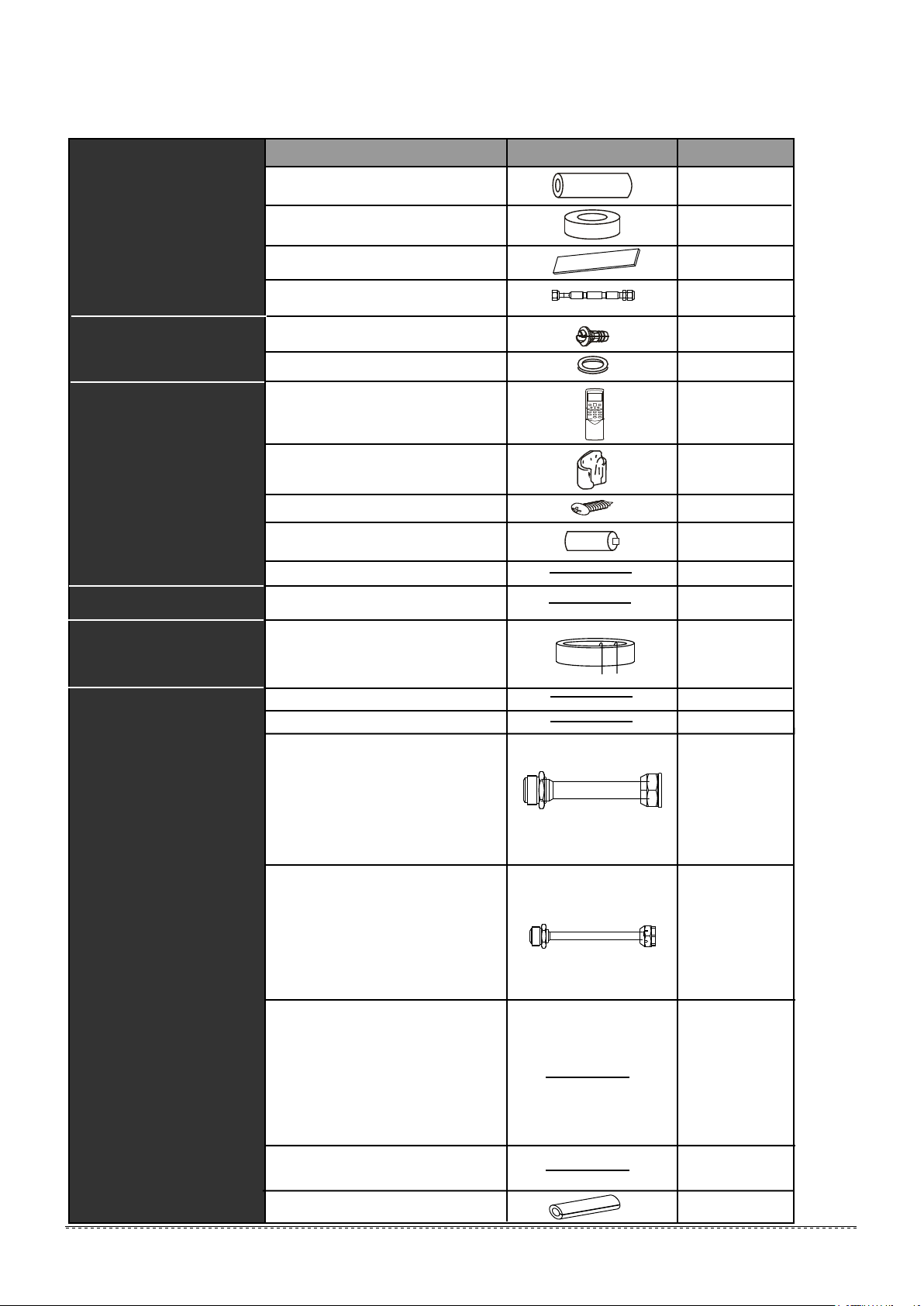
3. ATTACHED FITTINGS
Please check whether the following fittings are of full scope. If there are some spare fittings , please restore them carefully.
Table 3-1
Tubing & Fittings
Drainpipe Fittings
(for cooling & heating)
Remote controller & Its Frame
(Match with
remote controller )
Wire controller & Its Frame
(Match with wire controller )
EMC & Its Fitting
(for some models)
Others
NAME
1. Soundproof / insulation sheath
2. Binding tape
3.Seal sponge
4.Orifice
5. Drain joint
6. Seal ring
7. Remote controller
(on some models)
8. Frame
9.Mounting screw(ST2.9×10-C-H)
10.Alkaline dry batteries (AM4)
11. Remote controller manual
12. Wire controller
13. Magnetic ring
(twist the electirc wires L and N
around the magnetic ring to five
circles)
14. Owner‘s manual
15. Installation manual
16 .Transfer connector(Φ12.7-Φ15.9)/
( )
Φ0.5in-Φ0.63in
(Packed with the indoor unit )
(NOTE: Pipe size differ from appliance
to appliance.To meet different pipe size
requirement, sometimes the pipe
connections need the transfer connector
to install on the outdoor unit .)
17 .Transfer connector(Φ6.35-Φ9.52)/
( )
Φ0.25in-Φ0.375in
(Packed with the indoor unit )
(NOTE: Pipe size differ from appliance
to appliance.To meet different pipe size
requirement, sometimes the pipe
connections need the transfer connector
to install on the outdoor unit .)
18 .Transfer connector(Φ9.52-Φ12.7)/
( )
Φ0.375in-Φ0.5in
(Packed with the indoor unit,used for
multi-type models only )
(NOTE: Pipe size differ from appliance
to appliance.To meet different pipe size
requirement, sometimes the pipe
connections need the transfer connector
to install on the outdoor unit .)
19. Connecting wire for display (2M)
20. Cord protection rubber ring
SHAPE
QUANTITY
2
1
1
1
(on some models)
1
1
1
1
(on some models)
2
2
1
1
1
L
N
1
1
1
(on some models)
1
(on some models)
1
(on some models)
1
(on some models)
1
(on some models)
installation manual
3
4. INSPECTING AND HANDLING THE UNIT
At delivery, the package should be checked and any damage should
be reported immediately to the service agent.
When handling the unit, take into account the following:
Fragile, handle the unit with care.
1
Keep the unit upright in order to avoid compressor
damage.
Choose on before hand the path along which the unit is to be
2
brought in.
Move this unit as originally package as possible.
3
4
When lifting the unit , always use protectors to prevent belt
damage and pay attention to the position of the unit’s centre
of gravity.
5. INDOOR UNIT INSTALLATION
5.1 Installation place
The indoor unit should be installed in a location that meets
the following requirements:
There is enough room for installation and maintenance.
The ceiling is horizontal, and its structure can endure the
weight of the indoor unit.
The outlet and the inlet are not impeded, and the
influence of external air is the least.
The air flow can reach throughout the room.
The connecting pipe and drainpipe could be extracted out
easily.
There is no direct radiation from heaters.
CAUTION
Keep indoor unit, outdoor unit, power supply wiring and
transmission wiring at least 1 meter away from televisions
and radios. This is to prevent image interference and
noise in those electrical appliances. (Noise may be
generated depending on the conditions under which the
electric wave is generated, even if 1 meter is kept.)
5.2 Install the main body
1 Installing Ø10/Ø0.394in hanging screw bolts. (4 bolts)
Please refer to the following figures for positioning 4 screw
bolts.
Evaluate the ceiling construction and please install with
Ø0.394in hanging screw bolts.
/
Consult the construction personnels for the specific procedures.
Do keep the ceiling flat. Consolidate the roof beam to avoid
possible vibration.
Carry out the pipe and line operation in the ceiling after finishing
the installation of the main body. While choosing where to start
the operation, determine the direction of the pipes to be drawn
out. Especially in case there is a ceiling, position the refrigerant
pipes, drain pipes,indoor & outdoor lines to the connection
places before hanging up the machine.
The installation of hanging screw bolts.
Cut off the roof beam.
Strengthen the place that has been cut off, and consolidatethe roof beam.
After the selection of installation location, position the refrigerant pipes, drain pipes,indoor & outdoor wires to the connection
places before hanging up the machine.
The installation of hanging screw bolts.
Ø10
Maintena nce roomage
200mm/7.874in or more
300mm/11.811in or more
600mmX600mm/23.622inX23.622in
checking orifice
Fig.5-1
NOTE
Confirm the minimum drain tilt is 1/100 or more
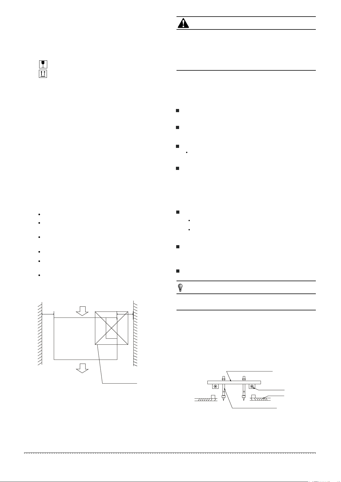
5.2.1
Wooden construction
Put the square timber traversely over the roof beam, then install
the hanging screw bolts. (Refer to Fig.5-2)
Timber over the beam
Roof beam
Ceiling
Hanging screw bolts
Fig.5-2
installation manual
4
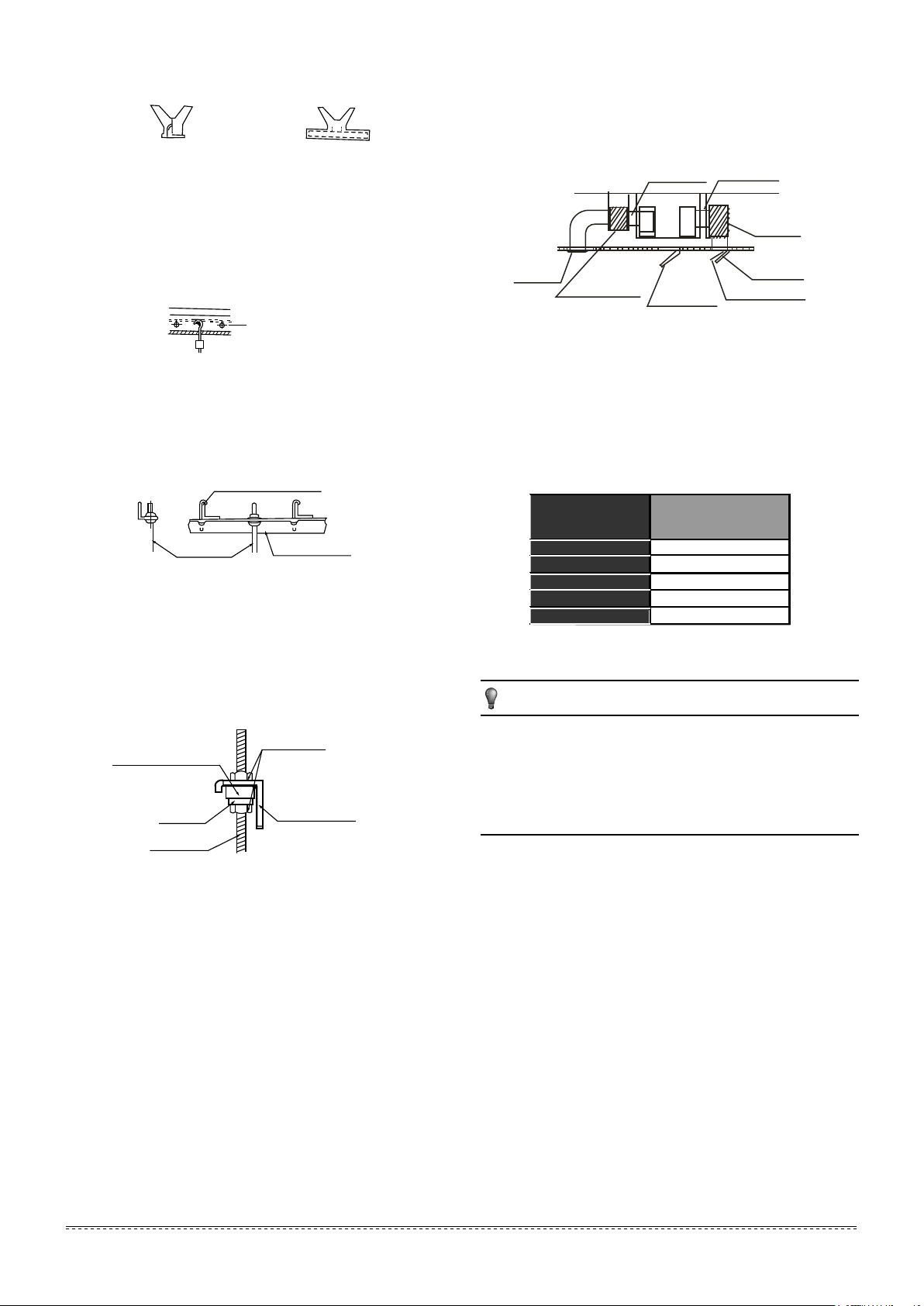
New concrete bricks
5.2.2
Inlaying or embedding the screw bolts. (Refer to Fig. 5-3)
(Blade shape insertion)
For Original concrete bricks
5.2.3
(Slide insertion)
Fig.5-3
3.
Air inlet and air outlet duct should be apart far enough to avoid
air passage short-circuit.
Recommended duct connection
4.
Canvas tie-in Canvas tie-in
Isolation booth
Use embedding screw bold, crock and stick harness.
(Refer to Fig.5-4)
Steel bar
Embedding screw bolt
(Pipe hanging and embedding screw bolt)
Fig.5-4
5.2.4
Steel roof beam structure
Install and use directly the supporting angle steel. (Refer to Fig.5-5)
Hanging screw bolt
Hanging bolts
2
Overhanging the indoor unit
(1) Overhang the indoor unit onto the hanging screw bolts with
block.
(2) Position the indoor unit in a flat level by using the level indicator,
unless it may cause leakage.
Shockproof cushion
Washer
Hanging
screw bolt
Supporting
angle steel
Fig.5-5
Screw nut
Overhang part
Fig.5-6
Air outlet
5. Please refer to the following static pressure to install
Table.5-1
Change the fan motor static pressure corresponding to external
duct static pressure.
Isolation booth
MODEL
(Btu/h)
12
18
24
30~36
42~60
checking orifice
Static Pressure
(Pa)
30
70
70
80
100
Air inlet
Air dust filter
Fig.5-7
NOTE
Do not put the connecting duct weight on the indoor unit.
1.
2.
When connecting duct, use inflammable canvas tie-in to prevent
vibrating.
3.
Insulation foam should be wrapped outside the duct to avoid
condensate and internal duct underlayer shall be added to reduce
the noise for special requirement.
5.3 Duct and accessories installation
Install the filter(optional) according to air inlet size.
1.
2.
Install the canvas tie-in between the body and duct.
installation manual
5
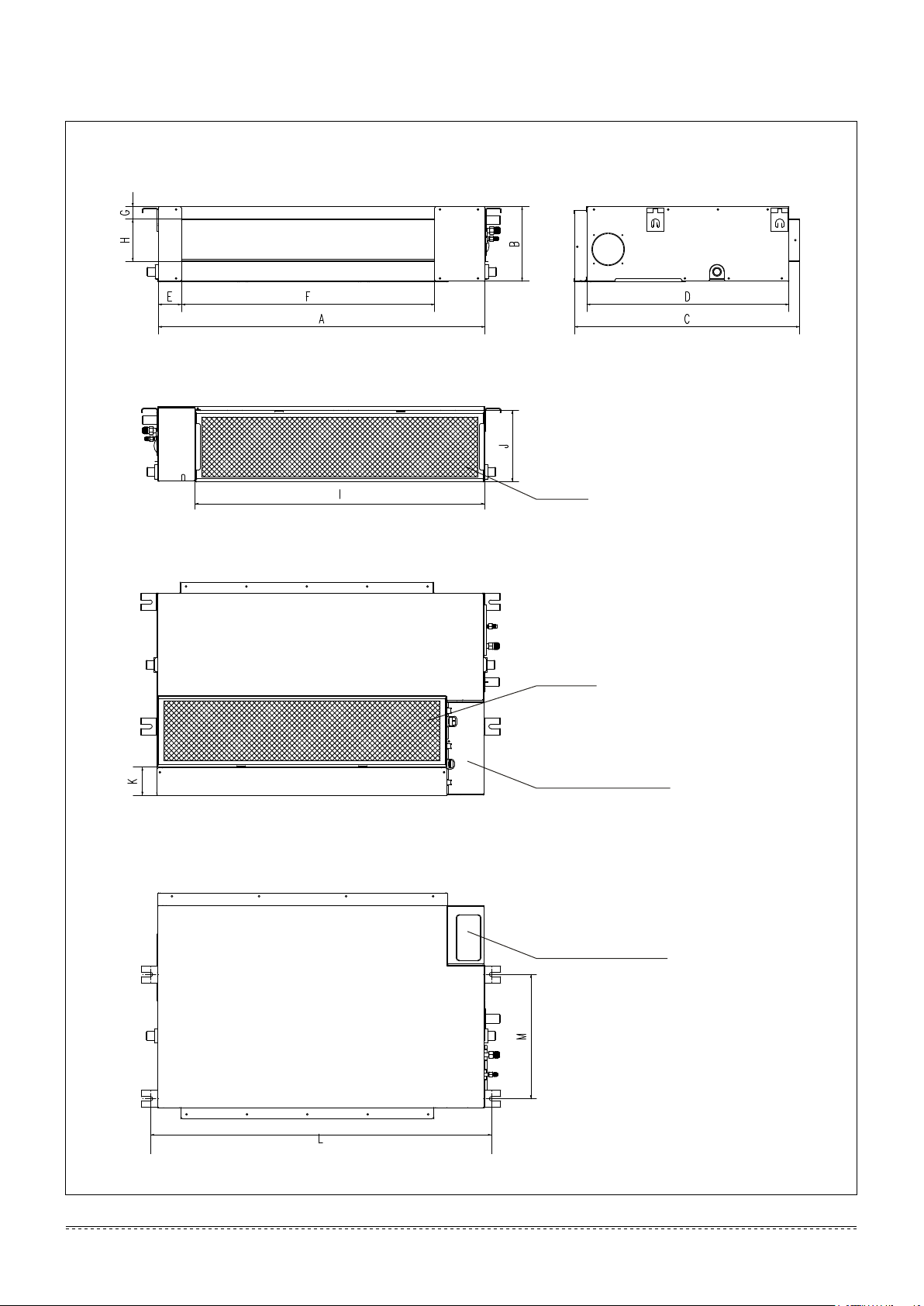
The positioning of ceiling hole, indoor unit and hanging screw bolts
Dimension and air outlet size
Air inlet size
Position size of descensional ventilation opening
Unit: mm
Air filter
Size of mounted hook
Air filter
Electric control box
Electric control box
installation manual
6
Fig.5-8
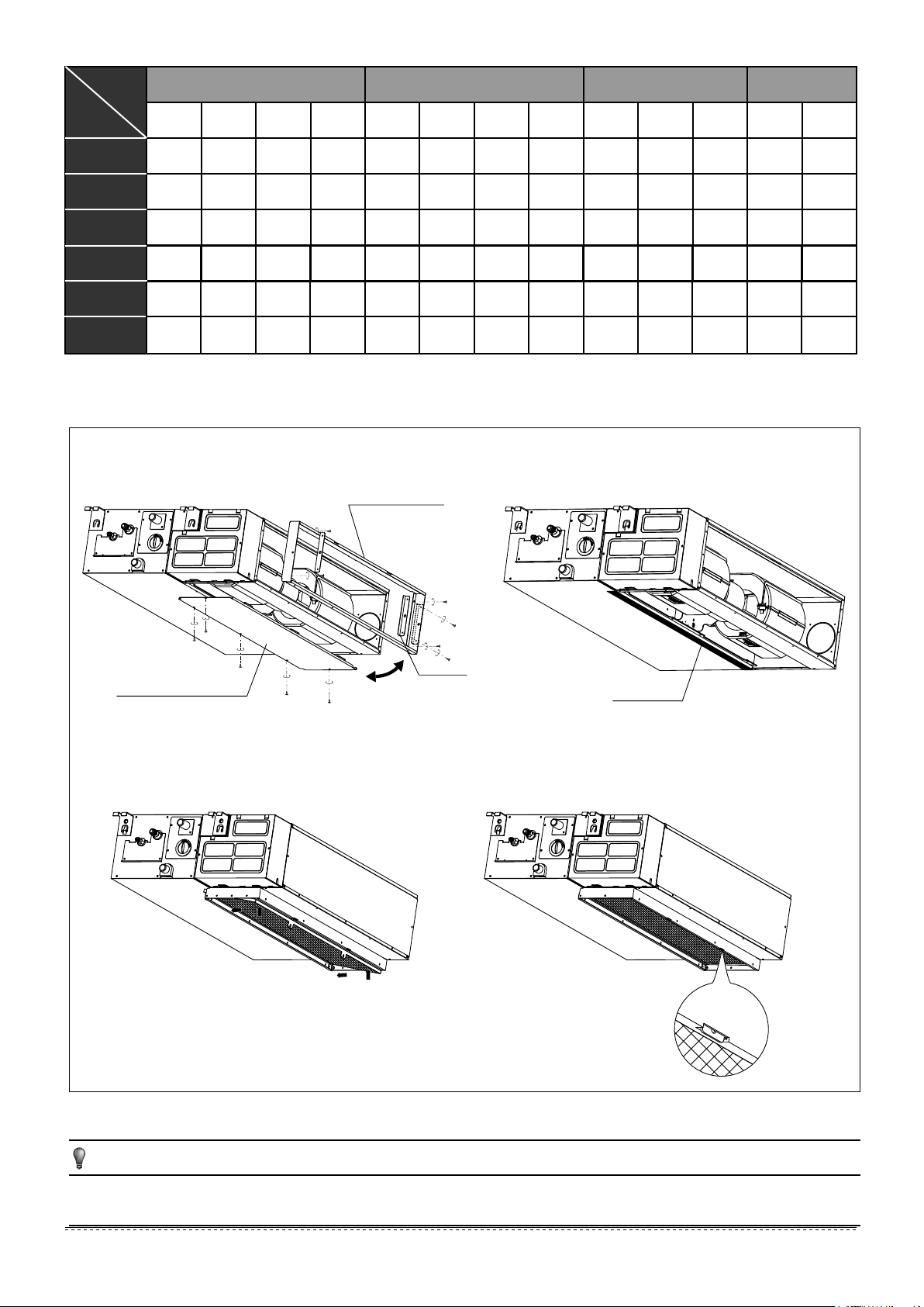
Table.5-2 mm
Outline dimension
air outlet opening size
air return opening size
Size of
mounted lug
A B C D E F G H I J K L M
12
12~18
24
36
(small model)
30~36
42~60
(in=mm/25.4)
700 210 635 570 65 493 35 119 595 200 80 740 350
920 210 635 570 65 713 35 119 815 200 80 960 350
920 270 635 570 65 713 35 179 815 260
920 270 635 570 65 713 35 179 815 260
1140 270 775 710 65 933 35 179 1035 260
1200
300 865 800 80 968 40 204 1094 288 45 1240 500
How to adjust the air inlet direction? (From rear side to under-side.)
1.
Take off ventilation panel and flange, cut off the staples at
side rail.
Air return flange
2.
Stick the attached seal sponge as per the indicating place in
the following fig, and then change the mounting positions of
air return panel and air return flange .
20 960 350
20 1180 490
45 1240 500
Dentilation panel
3.
When install the filter mesh, please plug it into flange inclined
from air return opening, and then push up.
Side rail
Seal sponge
4.
The installation has finish, upon filter mesh which fixing
blocks have been insert to the flange positional holes.
Fig.5-9
NOTE
All the figures in this manual are for explanation purpose only. They may be slightly different from the air
conditioner you purchased.The actual unit shall prevail.
installation manual
installation manual
7
 Loading...