

Pride Mobility Travel scooter series, 36, 40X, 44E, 40LX Owner's Manual
...

TRAVEL SCOOTER FEATURES TABLE
Model
Ä
AB CDAB COnUnit OffUnit
A
(
Release Lever
)B(Lock‐upPin)
Suspension
Seat Post Lights
Changea ble
ColorPanels
36
yyyyy
40X
y y yyy
44X
y y yyy
40E
y
y
AU only
y yyy y
44E
y
y
AU only
y yyy y
40LX
yy yyy yyy
44LX
yy yyy yyy
53
y y yyy y
53HD
y y yyy y
54
yy yyyyy
54HD
y y yyy y
73
yy yyy yyy
74
yy yyy yyy
83
yyyyy
84
yyyy
ConsoleStyle BatteryPackStyle FrameLock‐upStyleBatteryCharging Options*
*NOTE: Travel Scooter options vary by country. Please contact your Provider to determine which options
are available for your Travel Scooter.
NOTE: Please become familiar with your Travel scooter’s model number. The number can be found
on the product specification sheet in your owner’s package. Throughout this owner’s manual, Travel
Scooter attributes are indentified by model number (far left-hand column on Travel Scooter Features
Table). Knowing your unit’s model number will aid you in determining your particular Travel Scooter’s
unique characteristics.
INTENDED USE
The intended use of the Travel Scooter device is to provide mobility to persons limited to a seated position
that have the capability of operating a scooter.
NOTE: This owner’s manual is compiled from the latest specifications and product information
available at the time of publication. We reserve the right to make changes as they become necessary.
Any changes to our products may cause slight variations between the illustrations and explanations in
this manual and the product you have purchased. The latest/current version of this manual is available
on our website.
NOTE: This product is compliant with WEEE, RoHS, and REACH directives and requirements.
This product is manufactured by:
Pride Mobility Products Corporation
182 Susquehanna Avenue
Exeter, PA 18643-2694
USA
Copyright © 2012
INFMANU4392/Rev A/June 2012

CONTENTS
SAFETY GUIDELINES .....................................................................................................................3
I. SAFETY ........................................................................................................................................4
II. YOUR TRAVEL SCOOTER ...................................................................................................6
III. BATTERIES AND CHARGING ...........................................................................................13
IV. OPERATION .............................................................................................................................19
V. COMFORT ADJUSTMENTS ..............................................................................................21
VI. DISASSEMBLY AND ASSEMBLY ...................................................................................24
VII. BASIC TROUBLESHOOTING ...........................................................................................26
VIII. CARE AND MAINTENANCE .............................................................................................28
SAFETY GUIDELINES
WARNING! An authorized Pride Provider or qualified technician must perform the initial
setup of this scooter and must perform all of the procedures in this manual.
The symbols below are used throughout this owner's manual and on the scooter to identify warnings
and important information. It is very important for you to read them and understand them completely.
WARNING! Indicates a potentially hazardous condition/situation. Failure to follow
designated procedures can cause either personal injury, component damage, or
malfunction. On the product, this icon is represented as a black symbol on a yellow
triangle with a black border.
MANDATORY! These actions should be performed as specified. Failure to perform
mandatory actions can cause personal injury and/or equipment damage. On the product,
this icon is represented as a white symbol on a blue dot with a white border.
PROHIBITED! These actions are prohibited. These actions should not be performed at any
time or in any circumstances. Performing a prohibited action can cause personal injury
and/or equipment damage. On the product, this icon is represented as a black symbol
with a red circle and red slash.
Travel Scooter Series
3
I. SAFETY
PRODUCT SAFETY SYMBOLS
The symbols below are used on the Travel Scooter to identify warnings, mandatory actions, and prohibited
actions. It is very important for you to read and understand them completely.
NOTE: There are more warnings identified and explained in the Consumer Safety Guide that is
included with your Travel Scooter. Please become familiar with all the warnings and safety information
found in the Consumer Safety Guide and refer to this resource often.
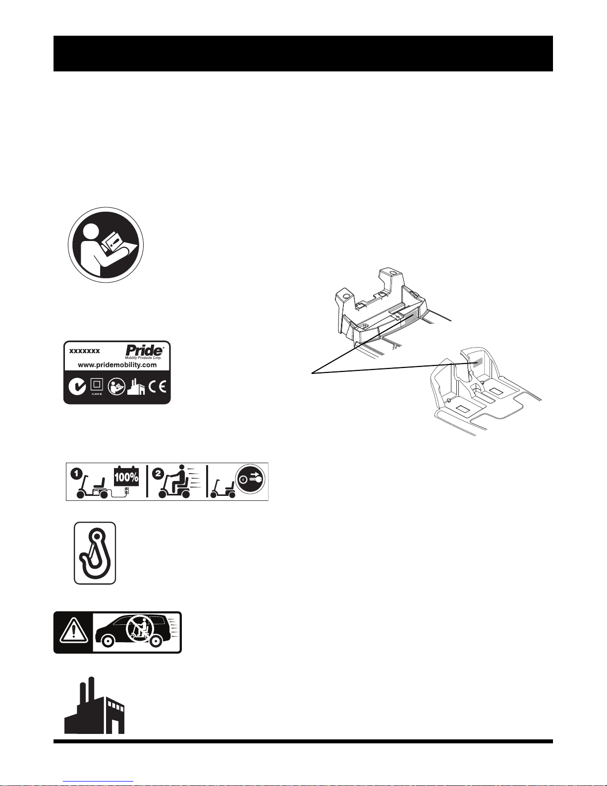
Read and follow the information in the owner’s manual.
MODELS: 83/84
Scooter information label.
MODELS: ALL MODELS
EXCEPT 83/84
Fully charge batteries before operating.
Remove key from an unattended Travel Scooter.
Indicates tie-down points on the Travel Scooter.
Does not meet 7176-19 standards for occupied transport in a motor
vehicle. When travelling in a motor vehicle, do not sit in your Travel
Scooter.
Manufactured in.
4
Travel Scooter Series

I. SAFETY
GENERAL
MANDATORY! Do not operate your new Travel Scooter for the first time without
completely reading and understanding this owner’s manual and the Consumer Safety
Guide.
Your Travel Scooter is a state-of-the-art life-enhancement device designed to increase mobility. We
provide an extensive variety of products to best fit the individual needs of the Travel Scooter user. Please
be aware that the final selection and purchasing decision regarding the type of Travel Scooter to be used
is the responsibility of the Travel Scooter user who is capable of making such a decision and his/her
healthcare professional (i.e., medical doctor, physical therapist, etc.).
The contents of this manual are based on the expectation that a mobility device expert has properly fitted
the Travel Scooter to the user and has assisted the prescribing healthcare professional and/or the authorized
Provider in the instruction process for the use of the product.
There are certain situations, including some medical conditions, where the Travel Scooter user will need
to practice operating the Travel Scooter in the presence of a trained attendant. A trained attendant can be
defined as a family member or care professional specially trained in assisting a Travel Scooter user in
various daily living activities.
As you begin using your Travel Scooter during daily activities, you will probably encounter situations in
which you will need some practice. Simply take your time and you will soon be in full and confident
control as you maneuver through doorways, on and off elevators, up and down ramps, and over moderate
terrain.
Additional general information can be found on the supplemental information sheets and booklets
included in your Owner’s Package. Please fully read and review the information, and keep it readily
available for future reference.
Below are some precautions, tips, and other safety considerations that will help you become accustomed
to operating the Travel Scooter safely.
PRE-RIDE SAFETY CHECK
Get to know the feel of your Travel Scooter and its capabilities. We recommend that you perform a safety
check before each use to make sure your Travel Scooter operates smoothly and safely.
Perform the following inspections prior to using your Travel Scooter:
Check the condition of the tires. Make sure they are not damaged or excessively worn.
Check all electrical connections. Make sure they are tight and not corroded.
Check all harness connections. Make sure they are secured properly.
Check the brakes to ensure they operate properly.
Check the battery condition meter to ensure the batteries are fully charged.
Ensure the manual freewheel lever is in drive mode before sitting on the Travel Scooter.
If you discover a problem, contact your authorized Provider for assistance. Please refer to the Contact
Information insert in your Owner’s Package.
Travel Scooter Series
5
II. YOUR TRAVEL SCOOTER
1 2 3 4
5
1 4 3 2
5
6
7
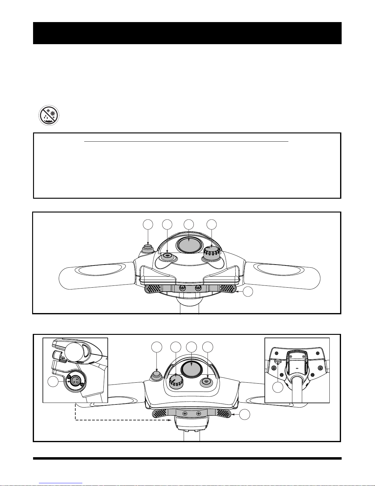
TILLER CONSOLE
The tiller console houses all controls needed to drive your Travel Scooter, including the key switch,
throttle control lever, horn button, speed adjustment dial, and the battery condition meter. Please refer to
the Travel Scooter Features Table on the inside of the front cover of this owner’s manual to determine
which console figure to choose. See figures 1 through 4.
PROHIBITED! Do not expose the tiller console to moisture. In the event that the tiller
console does become exposed to moisture, do not attempt to operate your Travel
Scooter until the tiller console has dried thoroughly.
IDENTIFICATION KEY FOR FIGURES 1 THROUGH 4
1. HORN 6. CHARGER POWER CORD RECEPTACLE (TILLER PORT)
2. KEY SWITCH 7. OFF-BOARD CHARGER FUSE
3. BATTERY CONDITION METER 8. LIGHT FUSE
4. SPEED ADJUSTMENT DIAL 9. LIGHT SWITCH
5. THROTTLE CONTROL LEVER
Figure 1. Tiller Console A
Figure 2. Tiller Console B
6
Travel Scooter Series
3
1
5
4
2
II. YOUR TRAVEL SCOOTER
3
7
8
5
6
9
2
4
1
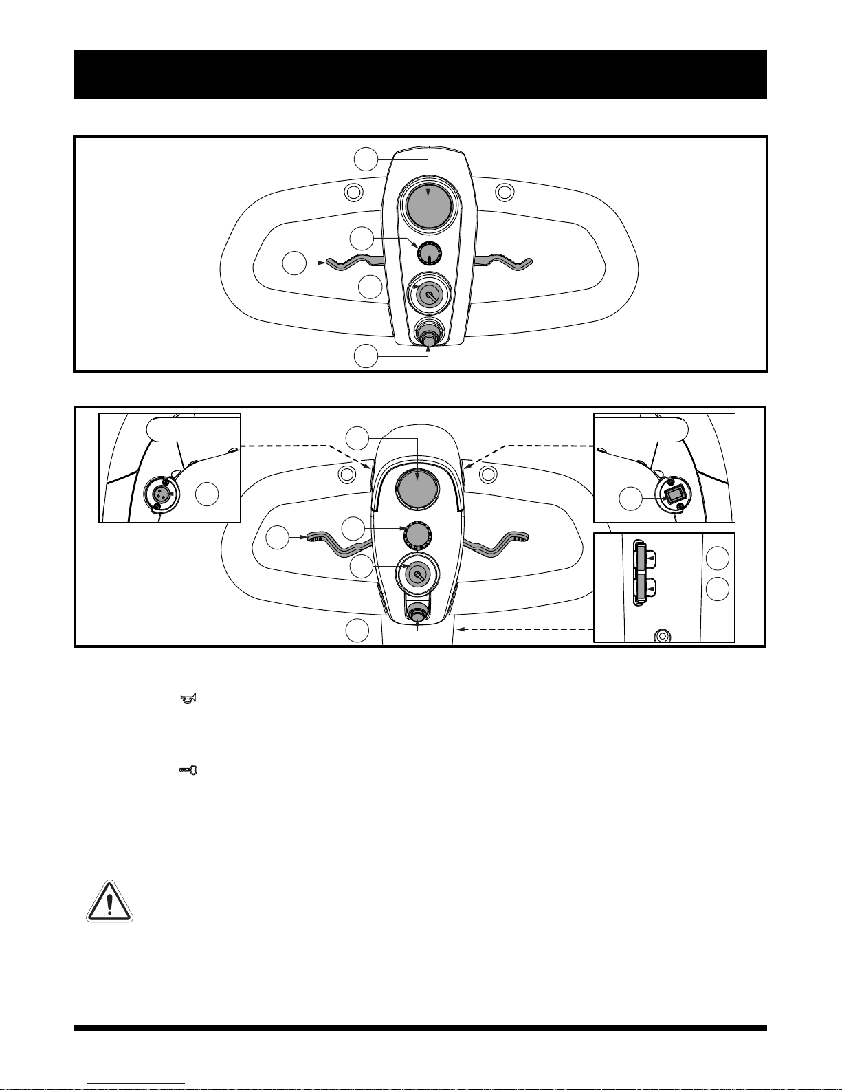
Figure 3. Tiller Console C
Figure 4. Tiller Console D
Horn Button
This button activates a warning horn. Your Travel Scooter must be turned on for the horn to be operational.
Do not hesitate to use the warning horn when doing so may prevent accident or injury.
Key Switch
Insert the key into the key switch and turn it clockwise to power up (turn on) your Travel Scooter.
Turn the key counterclockwise to power down (turn off) your Travel Scooter.
Although the key can be left in the key switch when the Travel Scooter is powered down, we recommend
removing it to prevent unauthorized use of your Travel Scooter.
WARNING! If the key is moved to the “off” position while your Travel Scooter is in motion,
the electronic brakes will engage and your Travel Scooter will come to an abrupt stop!
Battery Condition Meter
When the key is fully inserted into the key switch and turned clockwise to power up your scooter, this
meter indicates approximate battery strength. For further information on the battery condition meter,
see III. “Batteries and Charging.”
Travel Scooter Series
7
II. YOUR TRAVEL SCOOTER
1
3
2
Speed Adjustment Dial
This dial allows you to preselect and limit your Travel Scooter’s top speed.
The image of the tortoise represents the slowest speed setting.
The image of the hare represents the fastest speed setting.
Throttle Control Lever
This lever allows you to control the forward speed and the reverse speed of your Travel Scooter up to the
maximum speed you preset with the speed adjustment dial.
Place your right hand on the right handgrip and your left hand on the left handgrip.
Use your right thumb to push the right side of the lever to disengage your Travel Scooter’s brakes and
move forward.
Release the lever and allow your Travel Scooter to come to a complete stop before pushing the other
side of the lever to move in reverse.
When the throttle is completely released, it automatically returns to the center “stop” position and
engages your Travel Scooter’s brakes.
Lights Switch (If Equipped)
This switch controls your Travel Scooter’s lighting system. See figure 4.
Toggle the switch forward to turn on the lighting system.
Toggle the switch rearward to turn off the lighting system.
WARNING! Scooter users are required to use their lights when visibility is restricted —
day or night.
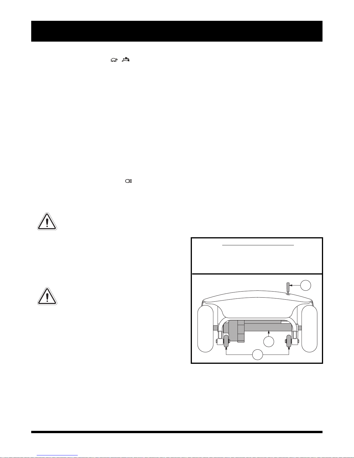
REAR COMPONENTS
The manual freewheel lever, anti-tip wheels, and
motor/transaxle assembly are located on your Travel
Scooter as shown. See figure 5.
WARNING! Before placing your
Travel Scooter into or taking it out of
freewheel mode, remove the key
from the key switch. Never sit on a
Travel Scooter when it is in
freewheel mode. Never put a Travel
Scooter in freewheel mode on any
incline.
Manual Freewheel Lever
Whenever you need or want to push your Travel
Scooter for short distances, you can put it in
freewheel mode.
1. Locate the manual freewheel lever at the top right
of the rear section.
2. Push forward on the manual freewheel lever to
disable the drive system and the brake system.
You may now push your Travel Scooter.
3. Push the manual freewheel lever rearward to
reengage the drive and the brake systems; this
takes your Travel Scooter out of freewheel mode.
IDENTIFICATION KEY
1. MANUAL FREEWHEEL LEVER
2. MOTOR/TRANSAXLE ASSEMBLY
3. ANTI-TIP WHEELS
Figure 5. Rear Components
8
Travel Scooter Series

II. YOUR TRAVEL SCOOTER
WARNING! When your Travel Scooter is in freewheel mode, the braking system is
disengaged.
Disengage the drive motors only on a level surface.
Ensure the key is removed from the key switch.
Stand to the side of the Travel Scooter to engage or disengage freewheel mode.
Never sit on a Travel Scooter to do this.
After you have finished pushing your Travel Scooter, always return it to the drive
mode to lock the brakes.
Motor/Transaxle Assembly
The motor/transaxle assembly is an electromechanical unit that converts electrical energy from your
Travel Scooter’s batteries into the controlled mechanical energy that drives the Travel Scooter’s wheels.
Anti-Tip Wheels
The anti-tip wheels are an integral and important safety feature of your Travel Scooter. They are bolted to
the frame at the rear of the Travel Scooter.
PROHIBITED! Do not remove the anti-tip wheels or modify your Travel Scooter in any way
that is not authorized by your Provider.
WARNING! The anti-tip wheels may cause interference with the smooth transition of your
Travel Scooter when ascending or descending a curb. Contact your authorized Provider
for more information.
Main Circuit Breaker (Reset Button)
When the voltage in your Travel Scooter’s batteries becomes low or the Travel Scooter is heavily strained
because of excessive loads or steep inclines, the main circuit breaker may trip to protect the motor and
electronics from damage. See figure 6.
The main circuit breaker reset button pops out when the breaker trips.
When the breaker trips, the entire electrical system of your Travel Scooter shuts down.
Allow a minute or two for your Travel Scooter’s electronics to “rest.”
Push in the reset button to reset the main circuit breaker.
If the main circuit breaker trips frequently, you may need to charge your batteries more often. You may
also need to have your authorized Provider perform a load test on your Travel Scooter’s batteries.
If the main circuit breaker trips repeatedly, see your authorized Provider for service.
Travel Scooter Series
9

III. YOUR TRAVEL SCOOTER
BATTERY PACK
Your Travel Scooter is equipped with an innovative, easy-to-remove battery pack. A handle on the top of
the battery pack makes it easy to lift the pack off of the Travel Scooter with one hand. The battery pack
contains two rechargable batteries, and may contain the charger power cord receptacle, the main circuit
breaker (reset button), and the battery pack fuse. See figure 6.
IDENTIFICATION KEY
1. BATTERY PACK
2. BATTERY PACK HANDLE 6. BATTERY CABLE WIRING HARNESS
3. CHARGER POWER CORD RECEPTACLE 7. BATTERY TERMINALS
4. BATTERY PACK FUSE 8. TILLER CONSOLE FUSE
5. MAIN CIRCUIT BREAKER (RESET BUTTON)
Battery Pack Style A Battery Pack Style B Battery Pack Style C
2
1
4
3
5 3 5
6
7
1
6
2
2
1
7 4
8 5
(Travel Scooter Deck)
Figure 6. Battery Pack
10
Travel Scooter Series
7
6
(Travel Scooter Deck)
 Loading...