

Page 1

®
BASIC OPERATION INSTRUCTIONS
Power Glide
TM
Page 2
WARNING! An authorized Pride Provider or a qualified
technician must perform the initial setup of this product
and must perform all of the instructions in this manual.
The symbols below are used throughout this owner's manual and on the
product to identify warnings and important information. It is very important
for you to read them and understand them completely.
WARNING! Indicates a potentially hazardous condition/
situation. Failure to follow designated procedures can
cause either personal injury, component damage, or
malfunction. On the product, this icon is represented as a
black symbol on a yellow triangle with a black border.
MANDATORY! These actions should be performed as
specified. Failure to perform mandatory actions can cause
personal injury and/or equipment damage. On the product,
this icon is represented as a white symbol on a blue dot
with a white border.
PROHIBITED! These actions are prohibited. These actions
should not be performed at any time or in any
circumstances. Performing a prohibited action can cause
personal injury and/or equipment damage. On the product,
this icon is represented as a black symbol with a red circle
and a red slash.
SAFETY GUIDELINES
Copyright © 2011
Pride Mobility Products Corporation
INFMANU3990/Rev B/April 2011
NOTE: These instructions are compiled from the latest specifications and
product information available at the time of publication. We reserve the
right to make changes as they become necessary. Any changes to our
products may cause slight variations between the illustrations and explanations in this manual and the product you have purchased. The latest/
current version of this manual is available on our website.
Page 3

Basic Operation Instructi o ns 3
www.pridemobility.com Power Glide
TABLE OF CONTENTS
LABEL INFORMATION.................................................................. 4
INTRODUCTION ............................................................................ 6
POWER GLIDE ..............................................................................8
INSTALLATION.............................................................................10
OPERATION OF THE POWER GLIDE........................................ 14
BATTERIES AND CHARGING.....................................................15
FAULT CODES..............................................................................19
SPECIFICATIONS.........................................................................20
WARRANTY..................................................................................21
Page 4
4 Basic Operation Instructions
Power Glide www.pridemobility.com
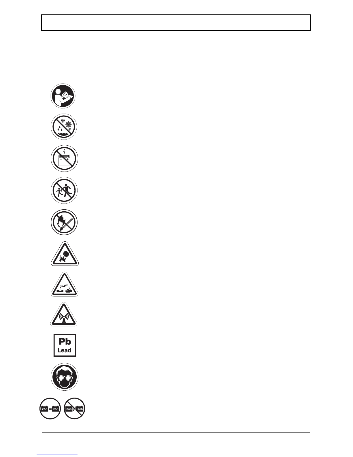
Read and follow the information in the owner’s manual.
Avoid exposure to rain, snow, ice, salt, or standing water
whenever possible. Maintain and store in a clean and dry
condition.
PRODUCT SAFETY SYMBOLS
The symbols below are used on the product to identify warnings, mandatory
actions, and prohibited actions. It is very important for you to read and
understand them completely.
Contains Lead.
Explosive conditions exist!
Wear safety goggles.
Keep tools and other metal objects away from battery
terminals. Contact with tools can cause electrical
shock.
LABEL INFORMATION
Corrosive chemicals contained in battery.
Do not allow unsupervised children to play near the
mobility product while the batteries are charging.
Do not expose to open flame.
Always replace the battery with the exact same type,
chemistry, and amp-hour (Ah) capacity. Refer to the
specifications table in this manual for recommended
type and capacities.
EMI/RFI - The product has been tested and passed at an
immunity level of 20 V/m.
Page 5
Basic Operation Instructi o ns 5
www.pridemobility.com Power Glide
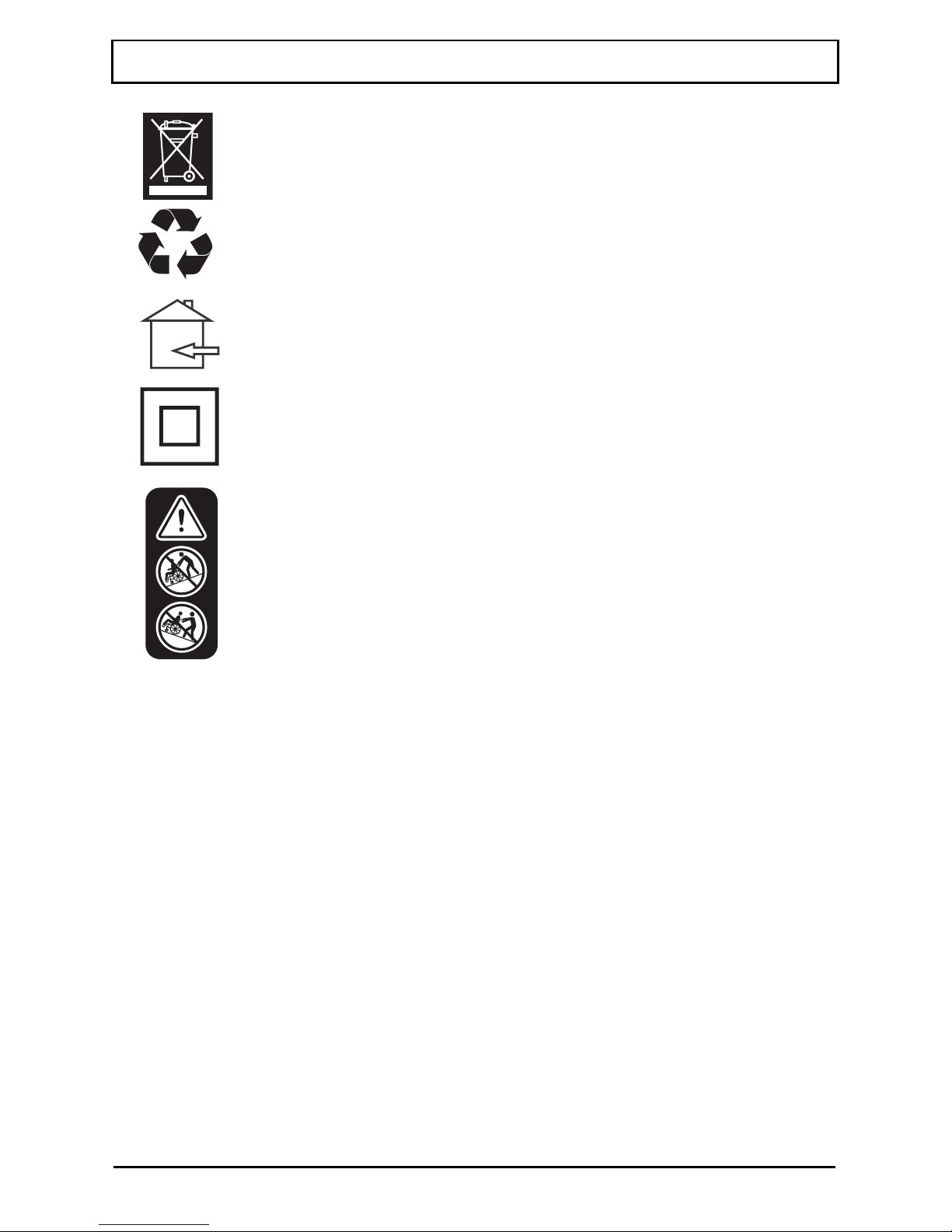
Disposal and recycling—Contact your authorized Pride
Provider for information on proper disposal of your
Pride product and its packaging.
LABEL INFORMATION
Battery charger for indoor use only.
Class II Equipment.
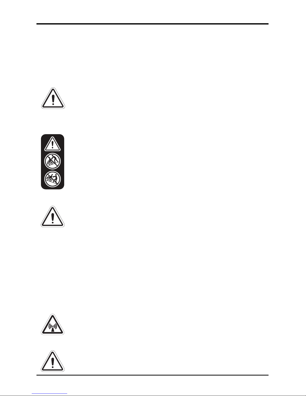
WARNING! Do not attempt to operate a wheelchair
equipped with a Power Glide on an incline or decline
greater than 2° (3.5%) without an attendant.
Page 6

6 Basic Operation Instructions
Power Glide www.pridemobility.com
INTRODUCTION
WELCOME to Pride Mobility Products (Pride). The product you have
purchased combines state-of-the-art components with safety, comfort, and
styling in mind. We are confident that the design features will provide you
with the conveniences you expect during your daily activities.
Understanding how to safely use and care for this product should bring you
years of trouble-free operation and service.
Read and follow all instructions, warnings, and notes in this manual and all
other accompanying literature before attempting to use this product for the
first time. In addition, your safety depends upon you, as well as your
provider, caretaker, or healthcare professional in using good judgement.
This manual is to be used in addition to the owner’s manual that came with
your wheelchair. If there is any information in this manual which you do not
understand, or if you require additional assistance for setup or operation,
please contact your authorized Pride Provider. Failure to follow the
instructions, warnings, and notes in this manual and those located on
your Pride product can result in personal injury and/or equipment
damage and will void Pride’s product warranty.
PURCHASER’S AGREEMENT
By accepting delivery of this product, you promise that you will not change,
alter, or modify this product or remove or render inoperable or unsafe any
guards, shields, or other safety features of this product; fail, refuse, or
neglect to install any retrofit kits from time to time provided by Pride to
enhance or preserve the safe use of this product.
INFORMATION EXCHANGE
We want to hear your questions, comments, and suggestions about this
manual. We would also like to hear about the safety and reliability of your
new Pride product, and about the service you received from your authorized
Pride Provider. Please notify us of any change of address, so we can keep
you apprised of important information about safety, new products, and new
options that can increase your ability to use and enjoy your Pride product.
NOTE: If you ever lose or misplace your product registration card or your
copy of this manual, contact us and we will be glad to send you a new one
immediately.
Page 7

Basic Operation Instructi o ns 7
www.pridemobility.com Power Glide
My Authorized Pride Provider Is:
Name: ______________________________________________________
Address: ____________________________________________________
Phone Number: _______________________________________________
Purchase Date: _______________________________________________
Page 8
8 Basic Operation Instructions
Power Glide www.pridemobility.com
POWER GLIDE
The Power Glide is designed to assist an attendant when pushing an occupied wheelchair up hills and ramps and over uneven ground.
WARNING! Do not operate the Power Glide when the
wheelchair is unoccupied.
WARNING! Ensure the on/off key is in the off position
before anyone transfers into or out of the wheelchair.
WARNING! Do not attempt to climb an incline without the
assistance of an attendant.
WARNING! Do not attempt to operate a wheelchair
equipped with a Power Glide outside of the safe limits as
recommended by the wheelchair manufacturer.
WARNING! Do not attempt to operate a wheelchair
equipped with a Power Glide on an incline or decline
greater than 2° (3.5%) without an attendant.
Electromagnetic and Radio Frequency Interference (EMI/RFI)
WARNING! Laboratory tests have shown that
electromagnetic and radio frequency waves can have an
adverse effect on the performance of electrically-powered
mobility vehicle.
Electromagnetic and Radio Frequency Interference can come from sources
such as cellular phones, mobile two-way radios (such as walkie-talkies),
radio stations, TV stations, amateur radio (HAM) transmitters, wireless
computer links, microwave signals, paging transmitters, and medium-range
mobile transceivers used by emergency vehicles. In some cases, these waves
can cause unintended movement or damage to the control system. Every
electrically-powered mobility vehicle has an immunity (or resistance) to
EMI. The higher the immunity level, the greater the protection against EMI.
This product has been tested and has passed at an immunity level of 20 V/m.
WARNING! Be aware that cell phones, two-way radios,
laptops, and other types of radio transmitters may cause
unintended movement of your electrically-powered mobility
vehicle due to EMI. Exercise caution when using any of
these items while operating your mobility vehicle and avoid
coming into close proximity of radio and TV stations.
WARNING! The addition of accessories or components to
the electrically-powered mobility vehicle can increase the
susceptibility of the vehicle to EMI. Do not modify your
assistive device in any way not authorized by Pride.
Page 9

Basic Operation Instructi o ns 9
www.pridemobility.com Power Glide
6
4
2 3
67
8
1
5
Figure 1. Power Glide Components (One-wheel Model Shown)
The Power Glide consists of (see figure 1):
1. Holding straps
2. Powerpack with lifting strap
3. Battery pack
4. Handle extensions
5. Battery charger
6. Mounting brackets (left and right shown)
7. Crossbar assembly (includes large and small)
8. Control module with bracket
WARNING! The electrically-powered mobility vehicle itself
can disturb the performance of other electrical devices
located nearby, such as alarm systems.
NOTE: For further information on EMI/RFI, go to the Resource Center
on www.pridemobility.com. If unintended motion or brake release
occurs, turn your power chair off as soon as it is safe to do so. Call Pride
or your authorized Pride Provider to report the incident.
Page 10

10 Basic Operation Instruc t io ns
Power Glide www.pridemobility.com
Follow these steps to install the Power Glide onto a wheelchair:
1. Ensure that you have all of the components that are shown in
figure 1
.
2. Install a mounting bracket to the bottom of each side of the wheelchair
frame and tighten the hardware. Keep both of the mounting brackets at
the same axle position on each side of the frame. See figure 2.
3. Insert the large crossbar into the crossbar housing as shown in figure 3,
and then lock it and the gearbox together with the four (4) supplied
screws.
NOTE: Do not tighten the main thumbscrew at this time.
4. Insert the small crossbar into the large crossbar and adjust the length so
that the combined crossbars securely fit into both mounting brackets.
See figure 3.
5. Confirm that the mounting brackets are locked.
6. Secure the combined crossbars with the thumbscrew. See figure 3.
7. Confirm that the powerpack is at the central position of the wheelchair
frame.
8. Tighten the main thumbscrew.
INSTALLATION
The Power Glide can be easily installed on any wheelchair that is 14-20 in.
(35.56-50.8 cm) in width.
WARNING! The Power Glide is heavy. See specifications
table. If you are unable to lift that much weight, be sure to
get help. Use proper lifting techniques and avoid lifting
beyond your capacity.
WARNING! Always remove the powerpack from the box
first, then remove the battery from the box. Do not remove
both together, as the battery may slip.
WARNING! Always install the powerpack onto the
wheelchair first, then install the battery.
MANDATORY! Do not exceed the weight capacity listed in
your wheelchair owner’s manual or 300 lbs./21 stone (136 kg),
whichever is less. Keep in mind that the maximum weight
capacity includes the combined weight of the user and any
accessories mounted to the wheelchair, including the
Power Glide.
Page 11

Basic Operation Instructi o ns 11
www.pridemobility.com Power Glide
Mounting
Bracket
Screws
Small
Crossbar
Large
Crossbar
Crossbar
Housing
Screws
Thumbscrew
Main
Thumbscrew
Figure 3. Crossbar Installation (One-wheel Model Show n)
Figure 2. Mounting Bracket Installation
Page 12

12 Basic Operation Instruc t io ns
Power Glide www.pridemobility.com
Screws
9. Fit the control module bracket to one of the back canes of the wheelchair,
making sure that the seatback does not touch the controller bracket when
the seatback is reclined, if equipped. Tighten the hardware.
See figure 4.
10. Place the battery pack on the powerpack. See figure 5.
11. Connect the battery plug on the powerpack to the plug on the battery.
See figure 5.
12. Route the cable from the powerpack up along the seatback and connect
the socket from the powerpack to the control module. See figure 6.
13. Attach each holding strap to the bottom of the wheelchair frame as
shown in figure 6.
14. Route the holding straps over the top of the installed Power Glide and
secure them with reusable hook and loop fasteners.
NOTE: The holding straps cannot be installed on all models of wheelchairs.
Figure 4. Controller Bracket Installation
Figure 5. Battery Pack Installation
Page 13

Basic Operation Instructi o ns 13
www.pridemobility.com Power Glide
Controller Cable
Holding Straps
Handle
Extensions
Figure 6. Controller Cable Routing and Holding Strap Installation (One-wheel Model
Shown)
Page 14

14 Basic Operation Instruc t io ns
Power Glide www.pridemobility.com
Status LED
Forward/
Reverse
Switch
Speed
Dial
Throttle Lever
On/Off Key
To install the handle extensions:
1. Remove the hand grip from the back cane.
2. Pry off the cap that covers the setscrews on the handle extension.
3. Loosen the setscrews.
4. Install the handle extension so that the flat side of the handle extension
is against the controller bracket. See figure 4 and figure 6.
5. Tighten the setscrews.
6. Reinstall the cap.
7. Install the handle extension on the other back cane following the above
steps.
OPERATION OF THE POWER GLIDE
Figure 7 provides information on the Power Glide control module
components. Use this diagram to familiarize yourself with the function and
location of each component before using the Power Glide.
Figure 7. Control Module Components
On/Off Key
The on/off key turns the system on and off.
NOTE: The wheelchair can be pushed when the Power Glide system is off.
Status LED
The status LED illuminates when the on/off key is in the on position and
also flashes fault codes. See “Fault Codes.”
Page 15

Basic Operation Instructi o ns 15
www.pridemobility.com Power Glide
Speed Dial
The speed dial controls the maximum speed of the Power Glide. Turn the
speed dial clockwise to increase maximum speed and counterclockwise to
reduce maximum speed.
NOTE: We recommend that the first few times you operate your Power Glide,
you set the speed to the slowest setting until you become familiar with its
operation. Always select a speed setting that is a comfortable walking pace.
WARNING! Do not pull or lift the handle extensions, if
installed. Pride recommends that handle extensions should
only be used to push the wheelchair. Check the setscrews
periodically to ensure proper securement.
Forward/Reverse Switch
The forward/reverse switch controls the direction of the Power Glide without having to manually reverse the wheelchair or lift the Power Glide off of
the ground. Push the switch toward the front of the wheelchair to go forward
and push the switch toward the rear of the wheelchair to go rearward.
NOTE: Switching the Power Glide into reverse may cause the powerpack
to flip over. Use caution when switching into reverse.
Throttle Lever
The throttle lever activates the Power Glide to the maximum speed set by
the speed dial. Pull the throttle lever up to activate the Power Glide.
BATTERIES AND CHARGING
Your Power Glide uses one long-lasting, 12-volt, deep-cycle battery. The
battery is sealed and maintenance free. Since it is sealed, there is no need to
check the electrolyte (fluid) level. Deep-cycle batteries are designed to
handle a longer and deeper discharge. Though they are similar in appearance to automotive batteries, they are not interchangeable. Automotive batteries are not designed to handle a long, deep discharge, and also are unsafe
for use in mobility devices.
MANDATORY! Battery posts, terminals, and
related accessories contain lead and lead
compounds. Wear goggles and gloves when
handling batteries and wash hands after
handling.
WARNING! Contact your authorized Pride
Provider if you have any questions regarding the
battery in your Power Glide.
Page 16

16 Basic Operation Instruc t io ns
Power Glide www.pridemobility.com
WARNING! Always protect the battery from freezing and
never charge a frozen battery.
WARNING! Explosive conditions exist!
WARNING! Corrosive chemicals contained in battery.
MANDATORY! Use only AGM or Gel-Cell battery to reduce
the risk of leakage or explosive conditions.
PROHIBITED! Removal of grounding prong can create
electrical hazard. If necessary, properly install an
approved 3-pronged adapter to an electrical outlet having
2-pronged plug access.
PROHIBITED! Do not connect an extension cord to the AC/
DC converter or the battery charger.
PROHIBITED! Do not allow unsupervised children to play
near the mobility product while the battery is charging.
PROHIBITED! Do not expose the battery to open flame.
Charging the Battery
The battery charger is essential in providing long life for your Power Glide
battery. It is designed to optimize your product’s performance by charging
the battery safely, quickly, and easily. The battery charger is only functional when the charger power cord is plugged into an electrical outlet.
The battery may encounter temperature extremes that can influence its performance. Extreme heat diminishes the charge on the battery; extreme cold
slows the available power and extends the time needed to recharge the battery. Keep the battery fully charged whenever possible and protect the battery from extreme heat or cold.
Page 17

Basic Operation Instructi o ns 17
www.pridemobility.com Power Glide
Battery
Pack
Battery
Charger
To Electrical Outlet
Figure 8. Battery Charging
Follow these steps to charge the
Power Glide (see figure 8):
1. Place the wheelchair equipped
with the Power Glide near a
standard electrical outlet.
2. Disconnect the black and white
charger harness extending from
the battery pack from the motor
harness.
NOTE: The battery charger is
equipped with an LED that indicates power and the state of
charge. A red LED indicates
power, an orange LED indicates
active charging, and a green LED
indicates that the battery is fully
charged.
3. Connect the charger harness to the black and white connectors on the
power cord extending from the battery pack, then plug the 3-pronged
plug into the electrical outlet.
4. When the battery is fully charged (a green LED will illuminate),
unplug the charger from the electrical outlet and then from the battery
pack.
PROHIBITED! Avoid exposure to rain, snow, ice, salt, or
standing water whenever possible. Maintain and store in a
clean and dry condition.
MANDATORY! Battery charger for indoor use only.
MANDATORY! Read the battery charging instructions in
this manual and in the manual supplied with the battery
charger before charging the batteries.
Page 18

18 Basic Operation Instruc t io ns
Power Glide www.pridemobility.com
Battery Replacement
MANDATORY! Battery posts, terminals, and
related accessories contain lead and lead
compounds. Wear goggles and gloves when
handling batteries and wash hands after
handling.
WARNING! Always replace the battery with
the exact same type, chemistry, and amp-hour
(Ah) capacity. Refer to the specifications
table in this manual for recommended type
and capacities.
To replace the battery in the battery pack:
1. Disconnect the battery pack from the powerpack. See figure 5.
2. Unzip the battery pack.
3. Disconnect the battery leads from the battery terminals and remove the
battery.
4. Put a new battery into the battery pack.
5. Connect the battery leads: red wire to the positive terminal (+) and black
wire to the negative terminal (-).
6. Zip the battery pack.
7. Reconnect the battery pack to the powerpack. See figure 5.
Page 19

Basic Operation Instructi o ns 19
www.pridemobility.com Power Glide
FAULT CODES
The status LED will flash fault codes when the Power Glide detects an abnormal condition in the electrical system. The status LED will continue to flash
the fault codes until the problem is fixed. The table below identifies the individual fault codes. If any of these fault codes persist, contact your authorized
Pride Provider.
Flash
Code
Probable
Cause
Impact
Possible
Solution
1 Battery needs
recharging
Will drive Battery charge is running
low. Recharge the battery
as soon as possible.
2 Battery volt-
age too low
Drive inhibited Battery is fully discharged.
Recharge the battery.
3 Battery volt-
age too high
Drive inhibited Battery charge is too high.
Excessive charging can
cause this fault.
Check the battery connections.
4 Current limit
time out
Drive inhibited The device has drawn too
much current for too long,
possibly due to a shorted
motor. Turn the device off
for a few minutes, then turn
back on. Check the motor
for shorts. Contact your
authorized Pride Provider if
the problem persists.
7 Throttle/speed
potentiometer
error
Drive inhibited The wiring may be faulty.
Contact your authorized
Pride Provider.
9 Internal error Drive inhibited Contact your authorized
Pride Provider.
Page 20

20 Basic Operation Instruc t io ns
Power Glide www.pridemobility.com
SPECIFICATIONS
Maximum speed:
1
Up to 3.4 mph (5.5 km/h)
Range:
1,4
Up to 10 miles (16 km)
Drive train: Single motor
Battery:
3
One 12-volt, deep-cycle 20 Ah
Battery charger: 1.5 amp off-board
Drive Wheels: 8 in. (20.32 cm), solid
Weight capacity: 300 lbs. (21 stone; 136 kg)
Overall size:
2
Height: 9.65 in. (24.5 cm)
Length: 11.81 in. (30 cm)
Width: 7.87 in. (20 cm)
Component weights:
5
Powerpack: One-wheel Model 14 lbs. (6.4 kg)
Two-wheel Model 17 lbs. (7.7 kg)
Battery: 15 lbs. (6.8 kg)
1
Varies with base model, user weight, terrain type, battery amp hour rating (Ah), battery
charge, battery condition, tire type, and tire condition.
2
Due to manufacturing tolerances and continued product improvement, this specification
can be subject to a variance of (+ or - ) 3%.
3
AGM or Gel-Cell type required. See “Batteries and Charging.”
4
Tested in accordance with ANSI/RESNA, WC Vol 2, Section 4 & ISO 7176-4 standards.
Results derived from theoretical calculation based on battery specifications and drive
system performance. Test conducted at maximum weight capacity.
5
Battery weight may vary based on battery manufacturer.
NOTE: This product conforms to all applicable ANSI-RESNA testing requirements and ISO 7176 series EN12183 and EN12184 standards. All specifications subject to change without notice.
Page 21

Basic Operation Instructi o ns 21
www.pridemobility.com Power Glide
WARRANTY
For one (1) year from the date of purchase, Pride will repair or replace at
our option to the original purchaser, free of charge, any part found upon
examination by an authorized representative of Pride to be defective in
material and/or workmanship.
SIX-MONTH LIMITED WARRANTY
Battery
The battery is covered by a separate six-month warranty, provided by the
battery manufacturer. The battery is not warranted by Pride.
WARRANTY EXCLUSIONS
Tires (wear items)
Circumstances beyond the control of Pride
Labor, service calls, shipping, and other charges incurred for repair of
the product, unless specifically authorized by Pride.
Repairs and/or modifications made to any part without specific consent
from Pride
Exclusions also include components with damage caused by:
Contamination
Abuse, misuse, accident, or negligence
Battery fluid spillage or leakage
Commercial use, or use other than normal
Improper operation, maintenance, or storage
NOTE: Gradual deterioration in performance because the battery has
been left in a discharged state, left in cold conditions for an extended
period of time, or worn out through heavy use is not covered.
SERVICE CHECKS AND WARRANTY SERVICE
Warranty service must be performed by an authorized Pride Provider. Do
not return faulty parts to Pride without prior written authorization. All transportation costs and shipping damage incurred while submitting parts for
repair or replacement are the responsibility of the purchaser.
Page 22

22 Basic Operation Instruc t io ns
Power Glide www.pridemobility.com
Failure to follow the instructions, warnings, and notes in the owner’s manual and those located on your Pride product can result in personal injury or
product damage and will void Pride’s product warranty.
There is no other express warranty.
IMPLIED WARRANTIES
Implied warranties, including those of merchantability and fitness for
a particular purpose, are limited to one (1) year from the date of purchase and to the extent permitted by law. Any and all other implied
warranties are excluded. This is the exclusive remedy. Liabilities for con-
sequential damages under any and all warranties are excluded.
Some states do not allow limitations on how long an implied warranty lasts
or do not allow the exclusion or limitation of incidental or consequential
damages. The above limitation or exclusion may not apply to you.
This warranty gives you specific rights, and you may also have other rights
which vary from state to state.
Please fill out and return the product registration card to Pride. This will aid
Pride in providing the best possible technical and customer service.
Page 23

23 Basic Operation Instruc t io ns
Power Glide www.pridemobility.com
NOTES
Page 24

*INFMANU3990*
®
Pride Mobility Products Corporation
182 Susquehanna Avenue
Exeter, PA 18643-2694
USA
Pride Mobility Products Company
380 Vansickle Road Unit 350
St. Catharines, Ontario L2R 6P7
Canada
Pride Mobility Products Ltd.
32 Wedgwood Road
Bicester, Oxon OX26 4UL
UK
Pride Mobility Products Australia Pty. Ltd.
21 Healey Road
Dandenong, 3175
Victoria, Australia
Pride Mobility Products Italia S.r.l.
Via del Progresso - ang. Via del Lavoro
Loc. Prato della Corte
00065-Fiano Romano (RM)
Pride Mobility Products Europe B.V.
Castricummer Werf 26
1901 RW Castricum
The Netherlands
 Loading...