

Page 1
SilverStar
SIL VER BOOM 300
™
www.silverst arlifts.com www .pridemobility .com
Page 2
SAFETY GUIDELINES
WARNING! An authorized Pride Provider or qualified technician must perform the initial
setup of this lift and must perform all of the instructions in this manual.
The symbols below are used throughout this owner's manual and on the product to identify warnings and important
information. It is very important for you to read them and understand them completely .
WARNING! Indicates a potentially hazardous condition/situation. Failure to follow
designated procedures can cause either personal injury, component damage, or
malfunction. On the product, this icon is represented as a black symbol on a yellow triangle
with a black border.
MANDATORY! These actions should be performed as specified. Failure to perform
mandatory actions can cause personal injury and/or equipment damage. On the product,
this icon is represented as a white symbol on a blue dot with a white border .
PROHIBITED! These actions are prohibited. These actions should not be performed at any
time or in any circumstances. Performing a prohibited action can cause per sonal injury
and/or equipment damage. On the product, this icon is represented as a black symbol with
a red circle and red slash.
Please fill out the following information for quick reference:
Pride Provider:_____________________________________________________________________
Address:__________________________________________________________________________
Phone Number: ___________________
Purchase Date:____________________ Serial Number:_________________________________
NOTE: This owner’s manual is compiled from the latest specifications and product information available at the time of publication. We reserve the right to make changes as they become necessary. Any
changes to our products may cause slight variations between the illustrations and explanations in this
manual and the product you have purchased. The latest/current version of this manual is available on
our website.
088 609 661
Copyright © 2007
Pride Mobility Products Corp.
INFMANU3210/Rev D/September 2007
Page 3

CONTENTS
I. INTRODUCTION......................................................................................................................... 4
II. SAFETY......................................................................................................................................... 5
III. INSTALLATION .......................................................................................................................... 8
IV. OPERATION............................................................................................................................... 15
V. TROUBLESHOOTING............................................................................................................ 19
VI . MAINTENANCE SCHEDULE .............................................................................................. 21
VII. WARRANTY................................................................................................................................22
www .silverstarlifts.com
3SilverBoom 300
Page 4

I. INTRODUCTION
W elcome to Pride Mobility Products Corporation (Pride). Congratulations on the purchase of your new SilverBoom.
The SilverBoom design combines the most advanced state-of-the-art components with modern, attractive styling.
W e are certain that the design features and trouble-free operation will add convenience to your daily living and
ensure complete satisfaction.
At Pride, your safety is important to us. Please read and follow all instructions in this manual before operat-
ing your SilverBoom for the first time. These instructions were produced for your benefit. Y our understanding
of these instructions is essential for the safe operation of your new SilverBoom.
Pride is not liable for damage to property or personal injury arising out of the unsafe use of a Pride SilverBoom. Pride
is also not liable for any property damage or personal injury arising out of the failure of any person and/or user to
follow the instructions and recommendations set forth in this manual or any other instructions or recommendations
contained in other SilverBoom related literature issued by Pride or contained on the Pride SilverBoom itself.
INTERNET AND PRIVATE PURCHASES
If you purchased your product over the internet or from a previous owner and have any questions about the safe
use and/or maintenance of the product, please visit Pride’s web site www.pridemobility.com or contact your
authorized Pride Provider .
PURCHASER’S AGREEMENT
By accepting delivery of this product, you promise that you will not change, alter, or modify this product or remove
or render inoperable or unsafe any guards, shields, or other safety features of this product; fail, refuse, or neglect to
install any retrofit kits from time to time provided by Pride to enhance or preserve the safe use of this product.
SHIPPING AND DELIVERY
Before using your lift, make sure your delivery is complete as some components may be individually packaged. If
you do not receive a complete delivery , please contact your authorised Pride Provider . Where damage has occurred during transport, either to the packaging or content, please contact the delivery company responsible.
INFORMA TION EXCHANGE
W e want to hear your questions, comments, and suggestions about this manual. W e would also like to hear about the
safety and reliability of your new SilverBoom , and about the service you received from your authorized Pride Provider.
Please notify us of any change of address, so we can keep you apprised of important information about safety , new
products, and new options that can increase your ability to use and enjoy your SilverBoom. Please feel free to
contact us at the address below:
Pride Mobility Products Corporation
Attn.: Customer Care Department
182 Susquehanna A ve.
Exeter, PA 18643-2694
customercare@pridemobility .com
800.424.8205
NOTE: If you ever lose or misplace your product registration card or your copy of this manual, contact
us and we will be glad to send you a new one immediately.
4
www .silverstarlifts.com
SilverBoom 300
Page 5

II. SAFETY
PRODUCT SAFETY SYMBOLS
The symbols below are used on the lift system to identify warnings, mandatory actions, and prohibited actions. It
is very important for you to read and understand them completely .
Read and follow the information in the owner’s manual.
Do not sit on mobility product while operating the lift system or during transport.
Do not lift people.
Maximum lifting capacity .
Pinch/Crush points created during assembly and/or operation.
Do not lift pets.
Do not extend the lifting strap past the warning label located on it.
www .silverstarlifts.com
5SilverBoom 300
Page 6

II. SAFETY
Avoid exposure to rain, snow , ice, salt, or standing water whenev er possible. Maintain
and store in a clean and dry condition.
Only authorized personnel may service this equipment.
Disposal and recycling-Contact y our authorized Pride Provider for information on proper
disposal of your Pride product and its packaging.
Disposal and recycling-Contact your authorized Pride Pro vider for information on proper
disposal of your Pride product and its packaging.
6
www .silverstarlifts.com
SilverBoom 300
Page 7

II. SAFETY
LIFTING CAPABILITIES
The SilverBoom 300 is designed to lift a maximum weight of 300 lbs. (136 kg). Under no circumstances should
the SilverBoom be made to exceed this weight limit. Subjecting the SilverBoom to the strain of lifting more than it
is designed to, may cause it to fail, resulting in damage to the mobility product and/or injury to the lift operator .
Refer to the mobility product owner’s manual for information on the overall weight of the mobility product before
lifting with the SilverBoom.
WARNING! Adding accessories, oversized batteries, or a different seat will increase the
weight of your mobility product. Verify with your authorized Pride Provider that the total
weight of your mobility product, including the additions, does not exceed 300 lbs. (136 kg).
INSTALLATION
Y our SilverBoom lift system was designed to be mounted primarily in a motor vehicle. Mounting your SilverBoom
on a platform, where the height of the lift may cause the lifting strap to extend beyond a safe point, can damage the
SilverBoom and injure the operator of the lift. The distance between the top of the boom-arm and the mobility
product should not exceed 70 in (178 cm) when the boom-arm is fully extended.
Read and fully understand the directions for drilling the mounting holes for the SilverBoom base before installing the lift system.
WARNING! Before drilling the mounting holes in your vehicle, make absolutely certain
through a visual inspection that there are no obstructions in the path of the drill bit, such
as the fuel tank, exhaust pipes, or electrical wires.
LIFTING NON-PRIDE ITEMS
The SilverBoom is an extremely versatile device, which users may employ to lift items other than Pride products.
Pride has no control over such use, nor can Pride anticipate every possible use to which a SilverBoom may be put.
Lifting non-Pride products with the SilverBoom is done at the operator’s own risk, and Pride accepts no liability
for damage or injury resulting from such use.
PRELIFT INSPECTION
Inspect the lifting strap of the SilverBoom before every use for twisting, fraying, and signs of wear. If signs of wear
become evident, have the strap replaced by your authorized Pride Provider .
WARNING! A frayed or worn lifting strap can snap, r esulting in damage to the mobility
product being lifted and injury to the lift operator.
OPERA TOR POSITIONING
Keep hands clear of the lifting strap while the SilverBoom is lifting/lowering a mobility product. The operator of the
lift should stand a safe distance from the unit being lifted/lowered to ensure that his/her feet are never positioned
under a raised mobility product.
TRANSPORT VEHICLE POSITIONING
Be sure your vehicle is parked on flat, level ground and the emergency brake is engaged before attempting to lift a
mobility product.
WARNING! Attempting to lift a mobility product when a vehicle is not on level ground will
cause the mobility product to swing toward or away from the vehicle, making it difficult to
get the mobility product into the vehicle.
www .silverstarlifts.com
7SilverBoom 300
Page 8
III. INSTALLATION
The SilverBoom can be installed in either side of your
vehicle. The illustrations demonstrate installation on the
right side.
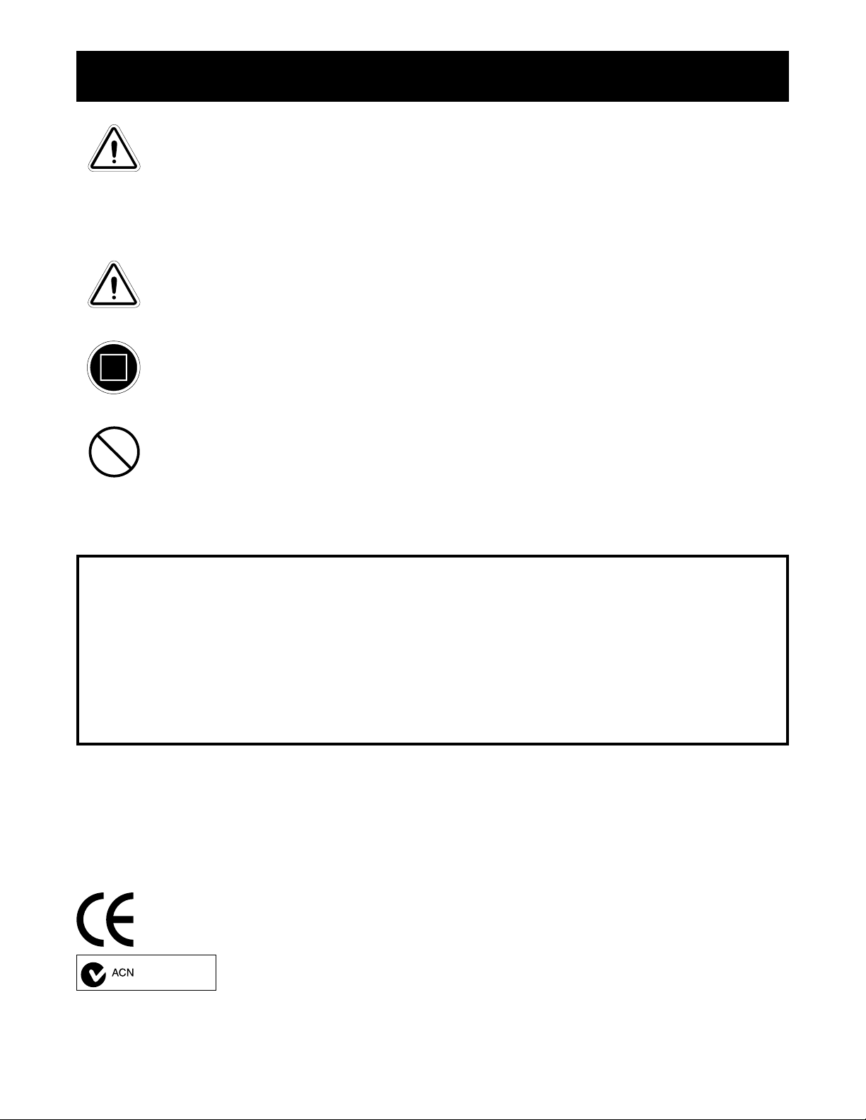
POWER ROTATING BASE SHR OUD REMOVAL
Installing a power rotating base requires that the base
shroud be removed in order to access the rear mounting
holes of the L-base. See figure 1.
1. Remove the 4 screws that secure the shroud to the
base.
2. Carefully lift the shroud up and off of the base.
SCREWS
SCREWS
NOTE: SilverBoom lifts that have a power rotating base should only be installed into a van or SUV.
DETERMINE L-BASE LOCA TION
WARNING! The lift is heavy.
Assistance may be necessary during
installation. Use proper lifting
techniques and avoid lifting beyond
your physical capability .
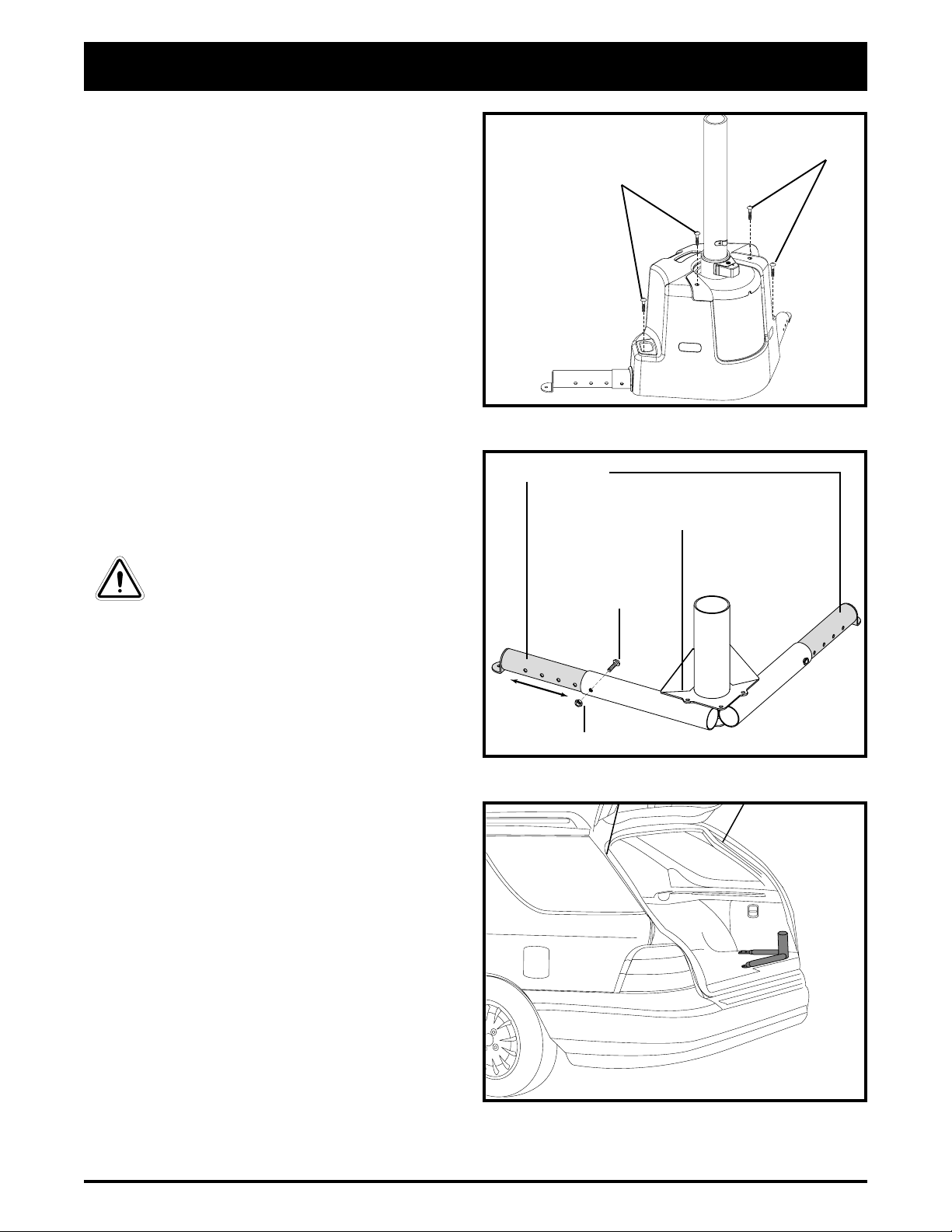
1. Assemble the L-Base. See figure 2. For optimal
use, insert the base extensions into the L-base at
their farthest extension point and install the hardware
(nuts and bolts). The base extensions can be adjusted to accommodate obstructions.
NOTE: Always insert the bolt from the inside of
the L-base. This allows the base extensions to be
properly tightened without rattling.
Figure 1. Power Rotating Base Shroud Removal
BASE EXTENSIONS
L-BASE
BOLT 55 MM (2.5”)
NUT
Figure 2. L-Base Extensions
2. Before permanently installing the lift, place the Lbase inside your vehicle in the area in which you intend to install it. See figure 3 for L-base positioning
for SUV’ s and vehicles with hatchbacks, or figure
4 for trunk installation.
NOTE: Positioning the L-base close to the rear
allows the boom-arm to stay as short as possible;
this enables the boom-arm to swing freely without
making contact with the motor vehicle.
8
www .silverstarlifts.com
Figure 3. L-Base (Hatchback Installation)
SilverBoom 300
Page 9

III. INSTALLATION
TRUNK INSTALLATION (SILVERBOOM
300 MANUAL RO T A TION ONL Y)
Position the L-base as shown in figure 3. Y ou may need
to situate the L-base so the wheel well does not interfere
with the L-base extensions. Ensure there is adequate room
for a mobility product to comfortably fit into the trunk.
ASSEMBLING THE LIFT
1. Insert the upper post into the L-base. See figure 5.
NOTE: When inserting the upper post into a power
rotating base, a slight adjustment of the sprocket
may be needed to align the insertion hole of the
sprocket with the lower post located inside the power
rotating base. This can be done by inserting the
upper post into the sprocket hole and moving it until
the upper post descends into the power rotating
base’s lower post.
WHEEL WELL
Figure 4. L-Base (T runk Installation)
!
MINIMUM OF 6” (15 CM)
!
2. Slide the height adjustment ring (see figure 6) over
the upper post and tighten the setscrew (a good starting point is approximately 12 in. (30.5 cm) down
from the top of the upper post). See figure 4. T o
ensure safe operation, the height adjustment ring must
be secured no closer than 6 in. (15 cm) from the top
of the upper post.
WARNING! Failing to tighten the
height adjustment ring setscrew
could cause damage to your lift,
mobility product, and vehicle.
NOTE: The height adjustment ring may need to be
adjusted down so the boom-arm has sufficient head
room to swing into a vehicle, or adjusted up so the
mobility product being lifted has ample room to
clear obstructions.
NOTE: If the length of the upper post for the
power rotating base needs to be made shorter during installation to ensure a proper fit into the vehicle, a qualified technician should remove the upper post cap, cut the necessary length from the
top of the post, then reinstall the upper post cap
See figure 13A.
HEIGHT ADJUSTMENT RING
UPPER POST
L-BASE
Figure 5. Upper Post Installation
SETSCREW
PROHIBITED! Do not cut any length
from the bottom of the upper post of
the power rotating base.
www .silverstarlifts.com
Figure 6. Height Adjustment Ring Assembly
9SilverBoom 300
Page 10

III. INSTALLATION
3. Lower the motor housing over the upper post until it
rests on the height adjustment ring. See figure 7.
WARNING! Pinch Point Hazard! Keep
hands clear of the upper post when
lowering the motor housing.
WARNING! The lift will be top heavy
until mounted securely. Get
assistance to help stabilize the lift
while swinging the boom-arm.
HA T CHB ACK INSTALLA TION- MINIVANS,
ST ATION WA GONS, ETC.
Once the lift is assembled and seated on the L-base,
close the hatch slowly to make sure it does not make
contact with it. If the lift is too close to the rear, adjust its
position slightly until the hatch can close without making
contact with the lift. Positioning the L-base close to the
rear allows the boom-arm to stay as short as possible.
This enables the lift to swing into the vehicle without contacting the far side of the vehicle.
Y ou may need to adjust the height of the motor housing
(see figures 7 and 8) or the length of the boom-arm
(see figure 9) so the boom-arm can swing freely with-
out hitting at any point inside the vehicle.
Figure 7. Motor Housing Installation
TOP OF POST
HEIGHT ADJUSTMENT RING
SECURE NO CLOSER THAN 6” (15 CM)
FROM THE TOP OF THE POST.
SETSCREW
MOTOR HOUSING HEIGHT ADJUSTMENT
The placement of the height adjustment ring determines
the height of the motor housing. See figure 8.
" Lower the ring when more room is needed over-
head to swing the boom-arm inside a vehicle.
" Raise the ring when more height is needed to enable
a mobility product to be lifted into a trunk.
T o adjust the height adjustment ring:
1. Loosen the setscrew on the ring. See figure 8.
2. Raise or lower the ring to the necessary height.
3. Tighten the setscrew .
Figure 8. Height Adjustment Ring Position
10
www .silverstarlifts.com
SilverBoom 300
Page 11

III. INSTALLATION
BOOM-ARM ADJUSTMENT
Before adjusting the boom-arm, lower the lifting hook
about 12 in. (30.5 cm). This will provide enough slack in
the strap to enable the adjustable portion of the boomarm (top tube) to be pulled out of the bottom tube to its
farthest adjustment hole. See figure 9.
BOW TIE COTTER PIN
TOP TUBE
ADJUSTMENT HOLES
T o adjust the boom-arm:
BOTTOM TUBE
1. Remove the bow tie cotter pin from the adjustment
pin and remove the adjustment pin.
2. Slide the top tube in or out to the desired adjustment
LIFTING HOOK
hole.
3. Align the adjustment holes of the top and bottom
ADJUSTMENT PIN
tube and reinsert the adjustment pin.
NOTE: Do not force the pin into the adjustment
hole. Be sure that the strap is not pinched when
inserting the pin.
Figure 9. Boom-arm Adjustment
4. Reinstall the bow tie cotter pin into the adjustment
pin to secure the boom-arm.
L-BASE INST ALLATION
T ools needed for installation:
" Power drill " 3/8” drill bit " Adjustable wrench " Socket set
" Phillips head screwdriver
After determining the ideal spot for your lift to be permanently mounted, remove the entire lift from the vehicle
except for the L-base.
1. Inspect the undercarriage of the vehicle where the lift L-base is located for obstructions that may hinder the
installation of the five (5) mounting bolts that will secure the L-base to the vehicle. Obstructions may consist of
electrical wiring, gas tank, bumper mounts, or exhaust pipes. You may need to adjust the base extensions to
clear obstructions. If possible, install the L-base with the base extensions fully extended. See figure 10.
WARNING! Explosive Conditions Hazard! The bumper mounts on some vehicles are gas
pressured. DO NOT drill into them.
2. If all is clear under the L-base, mark the position of the five (5) mounting holes and drill them using a 3/8-in. drill
bit. Drill all mounting holes from inside the vehicle. See figure 10.
3. Reinstall the L-base and align the mounting holes of the L-base with the holes you just drilled.
4. Position the T -bar on the end of the base support that runs parallel with the rear of the vehicle, and install a
mounting bolt and washer through it and the L-base. See figure 10.
NOTE: When the lift is installed inside a trunk, it may be necessary to remove the motor housing and
upper post for the trunk to close.
5. Install the four (4) remaining mounting bolts and washers onto the L-base.
www .silverstarlifts.com
11SilverBoom 300
Page 12

III. INSTALLATION
NOTE: Choosing the correct length bolt allows enough bolt-thread to pass through the undercarriage,
ensuring enough room for the mounting washer and nut to be installed securely.
6. From under the vehicle, install the mounting washers and nuts to all five (5) mounting bolts and tighten. See figure 10.
NOTE: The holes in the mounting washers are for working around obstructions. Choose the hole that
best works in the area you are installing the mounting bolts.
7. Place the L-base cap over the L-base and secure it with the supplied screws. See figure 11. Replace the base
shroud for power rotating base models.
8. Reinstall the upper post.
NOTE: When inserting the upper post into the power rotating base, a slight adjustment of the sprocket
may be needed to align the insertion hole with the lower post located inside the power rotating base. This
can be done by inserting the upper post into the sprocket and moving it until it descends into the power
rotating base’s lower post.
9. Reinstall the motor housing and make adjustments as necessary.
The lift is now fully assembled. See figure 12.
MOUNTING BOLTS
2” (50 MM) OR 3” (75 MM)
T-BAR
MOUNTING HOLE
WASHER
Figure 10. Securing The L-Base
12
www .silverstarlifts.com
MOUNTING WASHER
NUT
SilverBoom 300
Page 13

PHILLIPS HEAD SCREW 10 MM
III. INSTALLATION
L-BASE CAP
Figure 11. L-Base Cap Installation
MOTOR HOUSING
UPPER POST
L-BASE CAP
L-BASE
T-BAR
Figure 12. Fully Assembled Lift (SilverBoom 300 Shown)
ELECTRICAL WIRING INST ALLA TION
1. Route the lift’ s long power wire (starting at the lift) through the interior of the vehicle until you reach the
automobile battery . See figure 13 and 13A. Conceal the wire behind or under the interior panels (there
should be existing holes). Be certain that the wire is protected with a rubber grommet when passing it through
the metal panels and into the engine compartment. Inside the engine compartment, secure the wire to the
firewall and the inner fender with the supplied plastic wire ties. Use care not to cause abrasions to the power
wire. It is important to secure the power wire at various points along its run.
2. Insert the red positive (+) lead on the power wire into the spliced end of the red positive (+) battery lead, then
crimp the splice to secure the wire.
3. Connect the red positive (+) battery lead to the positive (+) battery terminal and the black negative (-) ground
wire to the negative (-) battery terminal.
WARNING! The red positive (+) wire must be connected directly to the positive (+) ba ttery
terminal.
WARNING! The black negative (-) wire must be connected directly to the negative (-)
battery terminal.
4. Connect the harness extending from the motor housing to the harness coming from the battery (black to black
and red to red).
www .silverstarlifts.com
13SilverBoom 300
Page 14

MOTOR HOUSING
III. INSTALLATION
ROUTE BLACK (-) GROUND WIRE TO
NEGATIVE (-) BATTERY TERMINAL
ROUTE RED (+) POWER WIRE TO
POSITIVE (+) BATTERY TERMINAL
FUSE 25-AMP
CRIMP HERE
Figure 13. SilverBoom 300 Electrical Wiring Connections
MOTOR HOUSING
UPPER
POSTCAP
POWER
ROTATING BASE
AUTOMOBILE BATTERY
ROUTE BLACK (-) GROUND WIRE TO
NEGATIVE (-) BATTERY TERMINAL
ROUTE RED (+) POWER WIRE TO
POSITIVE (+) BATTERY TERMINAL
FUSE 25-AMP
CRIMP HERE
Figure 13A. SilverBoom 300 With Power Rotating Base Electrical Wiring Connections
14
www .silverstarlifts.com
AUTOMOBILE BATTERY
SilverBoom 300
Page 15

IV. OPERATION
PROHIBITED! Avoid exposure to rain,
snow, ice, salt, or standing water
whenever possible. Maintain and
store in a clean and dry condition.
HAND/REMOTE CONTROL OPERA TION
Hand Control
The hand control for the SilverBoom 300 operates the lifting strap in two directions, up and down. See figure 14.
Power Rotating Base
The hand control for the SilverBoom 300 power rotating base operates the lifting strap up and down and the
boom-arm from side to side. See figure 14A.
PRESS TO OPERATE LIFTING
STRAP IN A DOWNWARD
DIRECTION
PRESS TO OPERATE
LIFTING STRAP IN AN
UPWARD DIRECTION
Figure 14. Hand Control (SilverBoom 300)
WARNING! Excercise extreme
caution when operating the power
rotaing base. Be aware of moving
parts.
Remote Control
The remote control for the SilverBoom 300 equipped
with a power rotating base operates the lifting strap up
and down and the boom-arm from side to side. See
figure 14B. The remote control works best when
used within 6 feet (182 cm) of the power rotating
base. When used in full sunlight, it i s recommend to
be within 3 feet (91 cm) of the power rotating base
for optimal performance.
Programing The Remote Control
1. Press any button on the remote control. Ensure that
the LED lights up.
2. Align the remote control and receiver on the base of
the lift in a straight line and keep them apart by at
least 12 inches (30.48 cm) . Bringing them closer
may lead to a failed programming operation.
3. Press the top button and the right button on the base
station and hold it for 5 seconds.
4. Release the buttons when the LED on the power
base begins to blink.
5. Try the remote control to ensure it works correctly .
PRESS TO OPERATE LIFTING STRAP IN AN UPWARD DIRECTION
PRESS TO ROTATE
THE BOOM-ARM TO
THE RIGHT
PRESS TO OPERATE LIFT IN A DOWNWARD DIRECTION
Figure 14A. Hand Control (SilverBoom 300 With A Power
Rotating Base)
PRESS TO OPERATE LIFTING STRAP IN AN UPWARD DIRECTION
PRESS TO ROTATE
THE BOOM-ARM TO
THE RIGHT
PRESS TO ROTATE
THE BOOM-ARM TO
THE LEFT
PRESS TO ROTATE
THE BOOM-ARM TO
THE LEFT
PRESS TO OPERATE LIFT IN A DOWNWARD DIRECTION
Figure 14B. Remote Control (SilverBoom 300 With A
Power Rotating Base)
www .silverstarlifts.com
15SilverBoom 300
Page 16

IV. OPERATION
Remote Control Battery Replacement
As with all electronic devices powered by batteries, the
battery of the remote control will eventually need to be
replaced. When the lift responds intermittently or no
longer responds to the commands from the remote
control, replace the battery .
DOCKING DEVICE T-BAR
T o replace the batteries of the r emote control:
1. Loosen and remove the screws from the back of the
remote control.
2. Remove the old battery . The battery slides in and
out from the side. Do not lift the battery straight up.
3. Replace old battery with one of the same size
(CR2430 3-volt).
4. Reassemble the remote control.
LIFTING THE MOBILITY PRODUCT
WARNING! Before operating the
SilverBoom for the first time, be
absolutely certain you ha v e the proper
docking device for your mobility product.
1. Prepare your mobility product for transport. Ensure
that the power is off or key is removed and properly
secure the batteries. You may also need to lower the
tiller and/or remove the seat.
2. Position your mobility product on the ground behind
the installed lift. Be sure that there is ample space
between the mobility product and the vehicle bumper
to ensure that the mobility product will not hit the
bumper while being raised. If the mobility product is
too far from the vehicle’s bumper , the mobility product will be dragged when attempting to lift it.
3. Position the boom-arm over the mobility product.
4. Operate the lift (via the hand/remote control in the
downward direction until the lifting hook reaches
the T-bar. The lift strap should drop straight down
to the T-bar. See figure 15 .
LIFTING HOOK
Figure 15. Lifting Hook Placement
Figure 16. Lifting Strap W arning Label
WARNING! Inspect the lifting strap before each use for twisting, fraying, and signs of wear .
" Keep tension on the lifting strap with your free hand when lowering the lifting hook.
" Lower the lifting hook only to the T -bar of the docking device.
WARNING! Do not extend the lifting strap past the warning label located on it. See figure 16.
5. Place the lifting hook onto the docking device T -bar . See figure 15.
6. Operate the lift in the upward direction.
16
www .silverstarlifts.com
SilverBoom 300
Page 17

IV. OPERATION
WARNING! Pinch/Crush Hazard!
Always keep hands clear of the lifting
strap while the SilverBoom is lifting/
lowering a mobility product. The
operator of the lift should stand a
safe distance away from the mobility
product being lifted/lowered to
ensure that feet are never positioned
under a raised mobility product.
Do not drag the mobility product into position using the
lift. If dragging occurs, your mobility product is too far
away from the vehicle. T o prevent dragging:
" Release the lifting strap tension then remove the hook
from the docking device.
" Correct the position of the mobility product.
" Attempt the lift again.
MANDA TOR Y! The SilverBoom 300 is
designed to lift a maximum weight
of 300 lbs (136 kg). Do not exceed
this limit.
Figure 17. Lifting The Mobility pr oduct
7. If the mobility product begins to tilt, lower it completely and adjust the docking device by moving
the pick-up bar in the direction of the tilt (when
using a C-arm).
8. T ighten the pick-up bar once the proper balance point
has been found (when using a C-arm).
9. Once the mobility product is raised high enough to
Figure 18. Securing The Boom-arm
fit into the vehicle, stop the lift. See figure 17.
10. Swing the boom-arm toward the vehicle. When the mobility product is securely in the vehicle, lower the lift
strap until all of the mobility product’ s wheels are on a solid surface.
11. If installed in a van or SUV, disconnect the hook from the docking device and attach it to the T-bar on the
base extension. (This prevents the boom-arm from swinging freely while the motor vehicle is in motion.)
Operate the lift in the upward direction until the strap is snug. See figure 18.
MANDATORY! Secure the boom-arm so it does not swing during transpor t. A swinging
boom-arm can be a hazard. If you cannot secure the boom-arm to prev ent it from swinging
freely, remov e the motor housing and lay it fla t inside the v ehic le.
WARNING! Do not overtighten the strap. Doing so may put excessive strain on the motor,
causing the circuit breaker to trip.
NOTE: If installed in a trunk, disconnect the black-red power harness (see figure 13 or 13A) and
remove the motor housing and upper post and place it in an area where it will be secure. The height of
the boom-arm will not allow the trunk to close.
www .silverstarlifts.com
17SilverBoom 300
Page 18

IV. OPERATION
12. Disconnect the power to the SilverBoom to prevent any accidental movement when transporting your
mobility product.
WARNING! Your SilverBoom was designed to be mounted primarily in a motor vehicle.
Mounting your SilverBoom on a platform, where the height of the lift may cause the lifting
strap to extend beyond a safe point, can damage the SilverBoom and injure the lift operator .
MANUAL LIFT STRAP OPERATION
The SilverBoom 300 with a power rotating base is
equipped with a lift strap manual override that serves as
backup in the event of a power failure. Using the supplied tool, rotate the manual crank located at the front of
the boom-arm motor housing clockwise or counterclockwise to move the lift strap up or down. See figure 19.
NOTE: Attaching the supplied tool to a power
drill will increase the speed at which the lifting
strap will move.
BOOM-ARM MANUAL ROTATION
(MODELS WITH A POWER ROTATING
BASE)
In the event of power failure, the boom-arm can be manually rotated by pulling back the flip handle to disengage
the securement pin. See figure 20. This allows the boomarm to swing freely . T o secure the boom-arm, rotate it
until the flip handle securement pin “clicks” into the upper post.
MANUAL OVERRIDE TOOL INSERTION POINT
Figure 19. Lift Strap Manual Override
BOOM-ARM
UPPER POST
FLIP HANDLE
18
Figure 20. Lift Strap Manual Override
www .silverstarlifts.com
SilverBoom 300
Page 19

V. TROUBLESHOOTING
LIFT WILL NOT OPERATE
" Check the circuit breaker reset button. Reset if nec-
essary. See figures 21 and 22.
" Ensure all harness connections are secure.
" Ensure the power wire leading to the positive
battery terminal is tight and not corroded.
" Check the fuse located on the red power wire near
the battery . If blown, replace with a new 25-amp
fuse. See figure 23.
WARNING! Do not use a higher rated
fuse than 25-amp. Doing so may
damage the lift’s electrical system.
WARNING! The replacement fuse
must exactly match the rating of the
old fuse. Failure to use properly rated
fuses may cause damage to the
electrical system.
LIFT STOPS OPERATING
If your SilverBoom is heavily strained because of excessive loads, the main circuit breaker (see figures
21 and 22) may trip to protect the motor and electronics from damage. When the breaker trips, the entire
electrical system shuts down.
CIRCUIT BREAKER RESET BUTTON
Figure 21. Circuit Breaker Reset Button SilverBoom 300
CIRCUIT BREAKER RESET BUTTON
WARNING! Never attempt to lift more
than 300 lbs. (136 kg) with the
SilverBoom 300.
T o reset the main cir cuit breaker:
1. Allow a minute or so for the electronics to “cool.”
2. Push in the reset button to reset the breaker.
If the breaker trips frequently , contact your authorized
Pride Provider.
Figure 22. Circuit Breaker Reset Button Power Rotating
Base Models
WORKING FUSE BLOWN FUSE
Figure 23. Fuse Replacement
www .silverstarlifts.com
19SilverBoom 300
Page 20

V. TROUBLESHOOTING
LIFTING STRAP TRAVELS IN OPPOSITE DIRECTION OF BUTTON BEING
PUSHED ON HAND CONTROL
Before each use, check that the lifting strap is traveling in the proper direction. If the belt travels in the wrong
direction when you press either the up or down button, you must restore proper lifting strap travel.
T o restor e proper lifting strap travel:
1. Pull slightly on the strap and operate the lift until the strap is extended completely past the “stop” warning label.
2. Allow the strap to rewind itself. Do not allow any twists in the belt.
Observe the travel of the belt: it should correspond with the button being pushed on the hand control. If you are still
experiencing problems, contact your authorized Pride Provider.
20
www .silverstarlifts.com
SilverBoom 300
Page 21

VI. MAINTENANCE SCHEDULE
The following routine maintenance should be performed at the indicated intervals. Failure to perform the required
maintenance procedures at the required intervals may void Pride’ s product warranty.
Perform prior to daily use:
" Inspect lift strap wear and replace if necessary .
" Inspect swivel hook for damage and to ensure it rotates freely .
" Inspect all external electrical connectors for damage and replace if necessary .
Perform every 6 months:
Inspect all mounting hardware for defects and a secure fit. Any hardware found to be loose, should be tightened or
replaced if necessary .
Perform every 6 –12 months:
" Remove upright post and lubricate with “General Purpose Petroleum Based Grease”.
" Remove plastic shrouds and visually inspect chains for damage and replace if necessary .
" Lubricate chains with “General Purpose Petroleum Based Grease”.
" Inspect plastic shrouds for cracks or damage and replace if necessary .
Perform every 36 months (Power Rotating Base only):
Remove plastic shroud and apply anti-seize lubricant to the main drive sprocket shaft.
NOTE: Use “Petroleum Based Anti-seize lubricant” only.
www .silverstarlifts.com
21SilverBoom 300
Page 22

VII. WARRANTY
THREE-YEAR TRANSFERABLE LIMITED WARRANTY
For three (3) years from the date of purchase, Pride Mobility Products will repair or replace at our option, free of
charge, any mechanical or electrical component found upon examination by an authorized representative of Pride
to be defective in material and/or workmanship.
This warranty does not extend to those items, which may require replacement due to normal wear and tear.
" Labor, service calls, shipping, and other char ges incurred for repair of the product, unless specifically
authorized by Pride Mobility Products Corporation IN ADV ANCE, are excluded.
Exclusions also include components with damage caused by:
" Contamination
" Abuse, misuse, accident, or negligence
" Battery fluid spillage or leakage
" Commercial use, or use other than normal
" Improper operation, maintenance, or storage
" Repairs and/or modifications made to any part without specific consent from Pride Mobility Products Corpo-
ration.
" Circumstances beyond the control of Pride
ONE-YEAR WARRANTY
The battery is covered by a separate one (1) year warranty provided by the battery manufacturer . The batteries are
not warranted by Pride Mobility Products Corporation.
SERVICE CHECKS AND WARRANTY SERVICE
An authorized Pride Mobility Products Provider must perform warranty service. Do not return faulty parts to Pride
Mobility Products without prior written authorization. All transportation costs and shipping damage incurred while
submitting parts for repair or replacement is the responsibility of the purchaser .
Failure to follow the instructions, warnings, and notes in the owner’s manual and those located on your Pride lift
product can result in personal injury or product damage and will void Pride’s product warranty .
There is no other express warranty .
IMPLIED WARRANTIES
Implied warranties, including those of merchantability and fitness for a particular purpose, are limited to one (1)
year from the date of purchase and to the extent permitted by law . Any and all implied warranties are excluded.
This is the exclusive remedy . Liabilities for consequential damages under any and all warranties are excluded.
Some states do not allow limitations on how long an implied warranty lasts or do not allow the exclusion of
limitation incidental or consequential damages. The above limitation or exclusion may not apply to you.
This warranty gives you specific rights, and you may also have other rights, which vary from state to state.
Please fill out and return the product registration card to Pride Mobility Products. This will aid Pride in providing
the best possible technical and customer service.
22
www .silverstarlifts.com
SilverBoom 300
Page 23

Page 24

*INFMANU3210*
 Loading...