

Page 1
BASIC OPERATION INSTRUCTIONS
TM
GC2 Controller
ACN# 088 609 661
Page 2
SAFETY GUIDELINES
WARNING! An authorized Pride Provider or a qualified
technician must perform the initial setup of this product
and must perform all of the instructions in this manual.
The symbols below are used throughout this owner’s manual and on the
controller to identify warnings and important information. It is very important for you to read them and understand them completely.
WARNING! Indicates a potentially hazardous condition/
situation. Failure to follow designated procedures can
cause either personal injury, component damage, or
malfunction. On the product, this icon is represented as a
black symbol on a yellow triangle with a black border.
MANDATORY! These actions should be performed as
specified. Failure to perform mandatory actions can cause
personal injury and/or equipment damage. On the product,
this icon is represented as a white symbol on a blue dot
with a white border.
PROHIBITED! These actions are prohibited. These actions
should not be performed at any time or in any
circumstances. Performing a prohibited action can cause
personal injury and/or equipment damage. On the product,
this icon is represented as a black symbol with a red circle
and a red slash.
NOTE: These instructions are compiled from the latest specifications and
product information available at the time of publication. We reserve the
right to make changes as they become necessary. Any changes to our
products may cause slight variations between the illustrations and explanations in this manual and the product you have purchased. The latest/
current version of this manual is available on our website.
088 609 661
Copyright © 2009
Pride Mobility Products Corporation
INFMANU3785/Rev C/October 2009
GC2 Controller www.pridemobility.com
Page 3

TABLE OF CONTENTS
LABEL INFORMATION ....................................................................4
INTRODUCTION .................................................................................5
GC2 CONTROLLER ...........................................................................7
PRECAUTIONARY GUIDELINES ...............................................7
OPERATING THE GC2 CONTROLLER .................................. 11
CONTROLLER COMMUNICATION CONNECTOR .............14
LOCK MODE .......................................................................................14
SLEEP MODE .....................................................................................15
THERMAL ROLLBACK ..................................................................15
FAULT CODES ..................................................................................16
CARE AND MAINTENANCE ........................................................17
WARRANTY ........................................................................................17
www.pridemobility.com GC2 Controller
Page 4
LABEL INFORMATION
PRODUCT SAFETY SYMBOLS
The symbols below are used on the controller to identify warnings, mandatory actions, and prohibited actions. It is very important for you to read and
understand them completely.
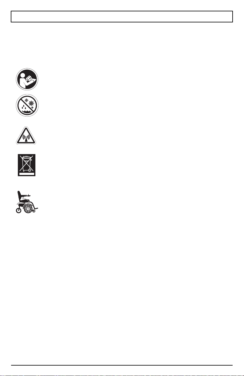
Read and follow the information in the owner’s manual.
Avoid exposure to rain, snow, ice, salt, or standing water
whenever possible. Maintain and store in a clean and dry
condition.
EMI-RFI — This product has been tested and passed at an
immunity level of 20 V/m.
Disposal and recycling — Contact your authorized Pride
Provider for information on proper disposal and recycling of
your Pride product and its packaging.
Use correct tie-down points for controller harness to
prevent the harness from getting caught in the drive tires,
pinched in the seat frame, or damaged when passing
through doorways.
GC2 Controller www.pridemobility.com
Page 5

Basic Operation Instructions 5
INTRODUCTION
WELCOME to Pride Mobility Products Corporation (Pride). The product
you have purchased combines state-of-the-art components with safety,
comfort, and styling in mind. We are confident that the design features will
provide you with the conveniences you expect during your daily activities.
Understanding how to safely operate and care for this product should bring
you years of trouble-free operations and service.
Read and follow all instructions, warnings, and notes in this manual before
attempting to operate your product for the first time. You must also read all
instructions, warnings, and notes contained in any supplemental
instructional booklets for the controller, front riggings, and/or seating
system that accompanied your power chair before initial operation. Your
safety depends upon you, as well as your provider, caretaker, or healthcare
professional, in using good judgement.
This manual is to be used in addition to the power base owner’s manual that
came with your power chair. If there is any information in this manual which
you do not understand, or if you require additional assistance for setup or
operation, please contact your authorized Pride Provider. Failure to follow
the instructions, warnings, and notes in this manual and those located
on your Pride product can result in personal injury and/or product
damage and will void Pride’s product warranty.
PURCHASER’S AGREEMENT
By accepting delivery of this product, you promise that you will not change,
alter, or modify this product or remove or render inoperable or unsafe any
guards, shields, or other safety features of this product; fail, refuse, or
neglect to install any retrofit kits from time to time provided by Pride to
enhance or preserve the safe use of this product.
INFORMATION EXCHANGE
We want to hear your questions, comments, and suggestions about this
manual. We would also like to hear about the safety and reliability of your
new Pride product, and about the service you received from your authorized
Pride Provider. Please notify us of any change of address, so we can keep
you apprised of important information about safety, new products, and new
options that can increase your ability to use and enjoy your Pride product.
www.pridemobility.com GC2 Controller
Page 6

6 Basic Operation Instructions
NOTE: If you ever lose or misplace your product registration card or your
copy of this manual, contact us and we will be glad to send you a new one
immediately.
My authorized Pride Provider is:
Name:
Address:
Phone Number:
Purchase Date:
GC2 Controller www.pridemobility.com
Page 7

Basic Operation Instructions 7
GC2 CONTROLLER
The GC2 controller is a fully-programmable, modular electronic controller
system that allows you to operate your power chair. It is designed to allow
the user to have complete control over chair movement and speed.
The controller has been pre-programmed to meet a typical user’s needs. The
program is set using either a personal computer with software provided by
the controller manufacturer or with a hand-held programmer, also provided
by the controller manufacturer.
WARNING! The controller program can affect speed,
acceleration, deceleration, dynamic stability, and braking.
If it is programmed incorrectly or outside of the safe limits
as determined by your healthcare professional, it can
create a dangerous situation. Only the power chair
manufacturer, an authorized representative of the
manufacturer, or a trained service technician should
program the controller.
PRECAUTIONARY GUIDELINES
Before operating the GC2 controller, please read the following. These
guidelines are provided for your benefit and will aid you in the safe operation of the control system.
Turn off the power to the controller when transferring to or from your
power chair.
Follow all of the procedures and heed the warnings as explained in your
power chair owner’s manual.
www.pridemobility.com GC2 Controller
Page 8

8 Basic Operation Instructions
Electromagnetic and Radio Frequency Interference (EMI/RFI)
WARNING! Laboratory tests have shown that
electromagnetic and radio frequency waves can have an
adverse effect on the performance of electrically-powered
mobility vehicles.
Electromagnetic and Radio Frequency Interference can come from sources
such as cellular phones, mobile two-way radios (such as walkie-talkies),
radio stations, TV stations, amateur radio (HAM) transmitters, wireless computer links, microwave signals, paging transmitters, and medium-range
mobile transceivers used by emergency vehicles. In some cases, these waves
can cause unintended movement or damage to the control system. Every
electrically-powered mobility vehicle has an immunity (or resistance) to
EMI. The higher the immunity level, the greater the protection against EMI.
This product has been tested and has passed at an immunity level of 20 V/m.
WARNING! Be aware that cell phones, two-way radios,
laptops, and other types of radio transmitters may cause
unintended movement of your electrically-powered
mobility vehicle due to EMI. Exercise caution when using
any of these items while operating your mobility vehicle
and avoid coming into close proximity of radio and TV
stations.
WARNING! The addition of accessories or components to
the electrically-powered mobility vehicle can increase the
susceptibility of the vehicle to EMI. Do not modify your
power chair in any way not authorized by Pride.
WARNING! The electrically-powered mobility vehicle itself
can disturb the performance of other electrical devices
located nearby, such as alarm systems.
NOTE: For further information on EMI/RFI, go to the Resource Center
on www.pridemobility.com. If unintended motion or brake release occurs,
turn your power chair off as soon as it is safe to do so. Call Pride or your
authorized Pride Provider to report the incident.
GC2 Controller www.pridemobility.com
Page 9

Basic Operation Instructions 9
GC2 Controller Features
Figure 1 provides information on the GC2 components and connections.
Use this diagram to familiarize yourself with the function and location of
each component before using the GC2 controller.
The following functions are available with the GC2 controller:
Joystick Control
The joystick is used to control the direction and speed of the power
chair.
Speed Adjustment
The user can increase or decrease the maximum speed of the power
chair.
Sleep Mode
This feature is designed to preserve battery charge and can be disabled
through programming.
Thermal Rollback
A safety feature designed to prevent the power chair from overheating
and causing damage to the motors or controller.
www.pridemobility.com GC2 Controller
Page 10

10 Basic Operation Instructions
Joystick
A multi-functional tool used
to control speed and
direction.
Speed Dial
Turn to increase or decrease
maximum speed.
Battery Condition Meter
Series of five colored LEDs
which display the battery
condition and fault codes.
On/Off Key
Press to power on or off the
power chair and controller.
Horn Key
Activates a warning horn.
Off-board Charger/
Programming Port
Used to charge or program
the power base.
Figure 1. GC2 Components and Connections
GC2 Controller www.pridemobility.com
Page 11
Basic Operation Instructions 11
3
4
1
6
5
2
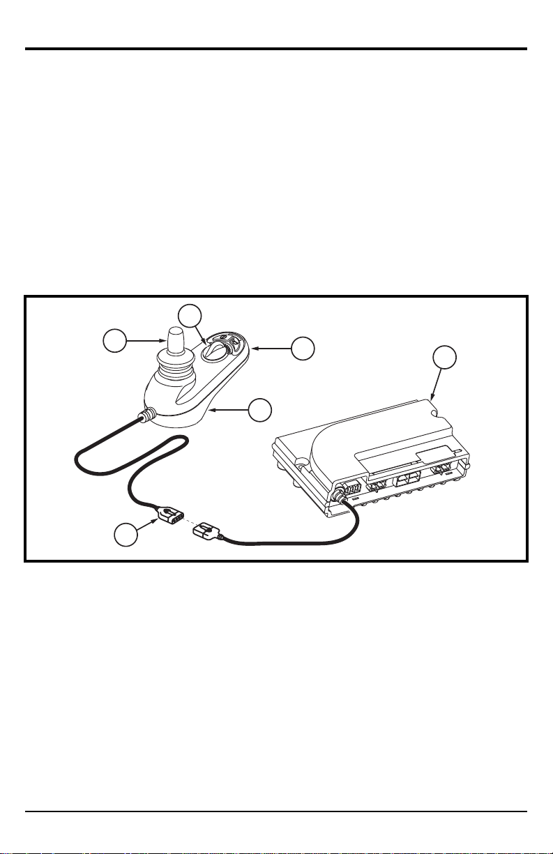
OPERATING THE GC2 CONTROLLER
The GC2 controller is used to operate your power chair and all of its
components.
The GC2 controller system consists of (see figure 2):
1. Joystick
2. Control panel
3. Joystick module
4. Off-board charging/programming socket
5. Power module
6. Controller communication connector
Figure 2. GC2 Controller
Joystick Control
The joystick controls the driving speed and direction of the power chair. When
the joystick is at rest, it is in the neutral (center) position, and the chair is
stationary. In order to drive the chair, the joystick must be taken out of neutral.
Moving the joystick in any direction will switch the chair from neutral to
drive, and the chair will move in the direction indicated by joystick position.
The farther away from the neutral position the joystick is, the faster the chair
will move in that direction. To stop chair movement, simply release the
joystick or move it back to the neutral position. The chair’s electromagnetic
brakes will engage after the chair has come to a controlled stop.
www.pridemobility.com GC2 Controller
Page 12

12 Basic Operation Instructions
BATTERY CONDITION METER
ON/OFF KEY HORN KEY
SPEED DIAL
JOYSTICK
Figure 3. Control Panel
Control Panel
The control panel is located directly in front of the joystick. It contains keys
and a dial that you will use to control your power chair. See figure 3.
On/Off Key
The on/off key turns the system on and off.
WARNING! Unless faced with an emergency situation, do
not use the on/off key to stop the chair. This will cause the
power chair to stop abruptly.
WARNING! Always turn the power off when you are
stationary to prevent unexpected movement.
Horn Key
The horn key activates a warning horn.
Speed Dial
The GC2 controller provides a speed dial to control the speed of the power
chair. See figure 3.
GC2 Controller www.pridemobility.com
Page 13

Basic Operation Instructions 13
To change the speed:
1. Push the on/off key to power on the chair and the controller.
2. To increase your speed, turn the speed dial clockwise.
3. To decrease your speed, turn the speed dial counterclockwise.
NOTE: We recommend that the first few times you operate your power
chair, you set the speed to the slowest setting until you become familiar
with your new power chair.
Battery Condition Meter
The battery condition meter consists of five LEDs arranged in an arc over
the on/off and horn keys. See figure 1. When functioning as the battery condition meter, this indicates the status of the electrical system using LED
codes. For example, as the battery voltage drops, the number of LEDs
reduces from right to left. When the battery capacity drops to 10% or below,
the left red LED will flash.
Battery condition meter codes are as follows:
Left Red LED Flashing Slowly or Steady: Battery charge is low;
charge the batteries as soon as possible.
Red and Yellow LEDs Flashing: Battery charge is low; charge the
batteries overnight.
LEDs Scroll From Left to Right: The controller is in inhibit or
charging mode.
LEDs Ripple Side-to-Side Twice, then All LEDs Flash Quickly:
joystick was not in the center position when the power was switched on, or
the controller system detected a fault; refer to “Fault Codes.”
The
NOTE: Your GC2 controller may be equipped with a battery charge
reminder feature. This feature will be activated if your power chair is
turned off AND it has been driven for 8 hours without being charged. If
equipped, the red LED on the battery condition meter will flash four (4)
times in 0.5-second intervals until the batteries are charged.
www.pridemobility.com GC2 Controller
Page 14

14 Basic Operation Instructions
CONTROLLER COMMUNICATION CONNECTOR
The controller communications connector provides the GC2 with a connection to the power module.
MANDATORY! Prevent controller harness damage! Avoid
routing the controller harness on the outside of the armrest
pad. Route the harness under the armrest or toward the
inside of the armrest pad. Use correct tie-down points for
the controller harness to prevent the harness from getting
caught in the drive tires, pinched in the seat frame, or
damaged when passing through doorways.
LOCK MODE
The controller is equipped with a feature that enables you to “lockout” unauthorized users.
To lock the controller:
1. While the power is on, press and hold the on/off key until it beeps
(approximately 1 second).
2. Release the on/off key.
3. Move the joystick to the full forward position until it beeps.
4. Move the joystick to the full rearward position until it beeps.
5. Release the joystick. There will be one long beep. The controller system
is now locked.
NOTE: The battery condition meter will be stepping up from left to right.
The sequence will continue to step up for two full cycles and then turn off.
To unlock the controller:
1. Press the on/off key to turn on the controller. The battery condition
meter will ripple the “locked” sequence.
2. Move the joystick to the full forward position until it beeps.
3. Move the joystick to the full rearward position until it beeps.
4. Release the joystick. There will be one long beep. The controller system
is now unlocked.
GC2 Controller www.pridemobility.com
Page 15

Basic Operation Instructions 15
SLEEP MODE
Your GC2 Controller has a sleep mode feature. Sleep mode is a built-in
circuit that automatically shuts off the main power if the joystick is not
moved in any direction for a period of time predetermined by the controller
program. When the programmed period of time is reached, the joystick will
beep and then power off. To restore power, push the on/off key.
THERMAL ROLLBACK
The GC2 controller is equipped with a thermal rollback circuit that monitors
the temperature of the chair’s motors and controller. If either exceeds the
safe operating temperature, the controller reduces the output to 50% of full
operation level. This reduces the chair’s speed and allows a cool down
period. Once the temperature returns to a safe level, the chair will resume
normal operation.
www.pridemobility.com GC2 Controller
Page 16

16 Basic Operation Instructions
FAULT CODES
The battery condition meter will flash fault codes when the controller system
detects an abnormal condition in the electrical system. All of the battery condition meter LEDs will flash a number of times quickly, then pause, then flash
again. The battery condition meter will continue to flash the fault codes until
the problem is fixed. The table below identifies the individual fault codes. If
any of these fault codes persist, contact your authorized Pride Provider.
Fault
Codes
1 Flash The batteries need charging.
2 Flashes
3 Flashes The left motor has a short to
4 Flashes
5 Flashes
Scroll Left
to Right
7 Flashes
8 Flashes
9 Flashes
Probable Causes Possible Solutions
There is a bad connection to
the batteries.
There is a bad connection on
the left motor.
the battery connection.
There is a bad connection on
the right motor.
The right motor has a short to a
battery connection.
The charge inhibit has been
activated.
There is a joystick fault. Make sure the joystick is in the cen-
There is a control system fault. Check power module and joystick
The park brakes have a bad
connection.
Check the battery connections. If the
battery connections are good, then try
charging the batteries.
Check the left motor connections and
wiring harnesses.
Contact your authorized Pride Provider.
Check the right motor connections
and wiring harnesses.
Contact your authorized Pride Provider.
Make sure that the battery charger is
not connected to the power base.
ter position and then power off and
on again.
module connections and wiring.
Check the left and right motor connections and wiring.
10 Flashes
GC2 Controller www.pridemobility.com
An excessive voltage has been
applied to the control system.
Check the battery connections.
Page 17

Basic Operation Instructions 17
CARE AND MAINTENANCE
Refer to your power chair owner’s manual for proper cleaning and disposal
instructions.
WARRANTY
Refer to your power chair owner’s manual for specific information on
controller warranty.
www.pridemobility.com GC2 Controller
Page 18

NOTES
GC2 Controller www.pridemobility.com
Page 19

NOTES
www.pridemobility.com GC2 Controller
Page 20

Pride Mobility Products Corporation
182 Susquehanna Avenue
Exeter, PA 18643-2694
USA
Pride Mobility Products Company
380 Vansickle Road Unit 350
St. Catharines, Ontario L2R 6P7
Canada
Pride Mobility Products Ltd.
32 Wedgwood Road
Bicester, Oxon OX26 4UL
UK
Pride Mobility Products Australia Pty. Ltd.
21 Healey Road
Dandenong, 3175
Victoria, Australia
Pride Mobility Products Italia S.r.l.
Via del Progresso - ang. Via del Lavoro
Loc. Prato della Corte
00065-Fiano Romano (RM)
Pride Mobility Products Europe B.V.
Castricummer Werf 26
1901 RW Castricum
The Netherlands
*INFMANU3785*
 Loading...