

Page 1
Mobility Products Australia Pty. Ltd.
www.pridemobility.com
®
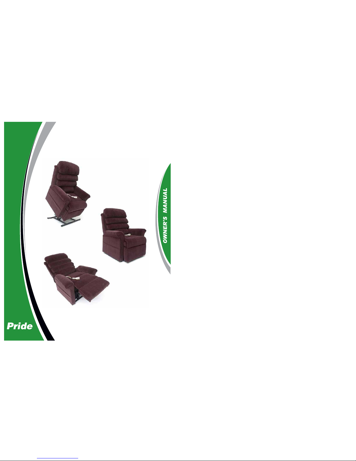
LIFT CHAIR
SERIES
Available From
Moreton Medical Equipment
Ph: (07) 3284 2811
1/107 Anzac Ave, Redcliffe
www.moretonmedicalequipment.com.au
Page 2
LIFT CHAIR SERIES
088 609 661
SAFETY GUIDELINES
The symbols below are used throughout this owner's manual and on the product to identify warnings and
important information. It is very important for you to read them and understand them completely.
WARNING! Indicates a potentially hazardous condition/situation. Failure to follow
designated procedures can cause either personal injury, component damage, or
malfunction. On the product, this icon is represented as a black symbol on a yellow
triangle with a black border.
MANDATORY! These actions should be performed as specified. Failure to perform
mandatory actions can cause personal injury and/or equipment damage. On the
product, this icon is represented as a white symbol on a blue dot with a white
border.
PROHIBITED! These actions are prohibited. These actions should not be performed
at any time or in any circumstances. Performing a prohibited action can cause
personal injury and/or equipment damage. On the product, this icon is represented
as a black symbol with a red circle and red slash.
Please fill out the following information for quick reference:
Pride Provider:
Address:
Phone Number:
Purchase Date: Serial Number:
NOTE: This owner’s manual is compiled from the latest specifications and product information
available at the time of publication. We reserve the right to make changes as they become necessary. Any changes to our products may cause slight variations between the illustrations and
explanations in this manual and the product you have purchased. The latest/current version of
this manual is available on our website.
This product is manufactured by:
Pride Mobility Products Corporation
182 Susquehanna Avenue
Exeter, PA 18643-2694
USA
Copyright © 2011
Pride Mobility Products Australia Pty. Ltd.
INFMANU1767/Rev J/February 2011
Page 3
LABEL INFORMATION
LIFT CHAIR SERIES
PRODUCT SAFETY SYMBOLS
The symbols below represent labels used on the product to identify warnings, mandatory actions, and prohibited actions. It is very important for you to read and understand t hese symbols comple tely. Do not remove
these labels from your product. Please note that not all of the symbols may be used on your lift chair model.
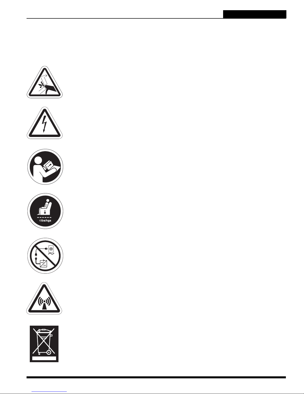
Pinch/Crush Points Hazard! Do not place objects or appendages in the path
of moving parts.
Electrical Hazard
Read and follow the information in the owner’s manual.
Maximum weight capacity
Do not connect an extension lead to the AC/DC converter or the battery
charger.
This product has been tested and complies to IEC 60601-1-2.
Properly dispose of all electronic components, including the external
transformer, hand control, batteries, actuator motors, and wiring. Contact
your authorised Pride Provider for more information.
Lift Chair Series www.pridemobility.com 3
Page 4
LIFT CHAIR SERIES
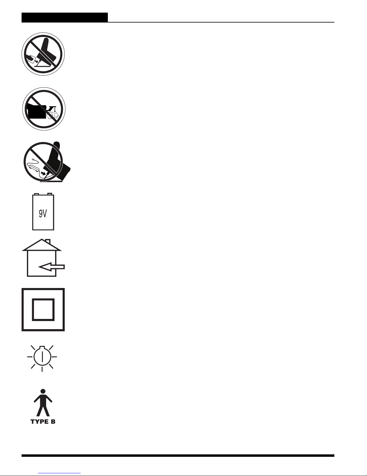
Do not place objects under lift chair. Make sure area is clear of obstructions,
including pets and small children during operation.
Do not place objects under the footrest when lift chair is in fully reclined
position. Make sure area is clear of obstructions, including pets and small
children during operation.
Do not cover or place the external transformer under the chair. Keep in an
open, well-ventilated area free from foreign material and away from possible
pinch points.
LABEL INFORMATION
Battery Door Location
Indoor Use Only. Avoid exposure to rain, snow, ice, salt, or standing water.
Maintain and store in a clean and dry environment.
Cla s s II E qu i p men t
Green LED indicates power to the unit is on. Not applicable to all models.
Degree of protection against electric shock.
4 www.pridemobility.com Lift Chair Series
Page 5

TABLE OF CONTENTS
LIFT CHAIR SERIES
SAFETY GUIDELINES .......................................................................................... 2
LABEL INFORMATION ......................................................................................... 3
I. INTRODUCTION................................................................................................ 6
SAFETY ........................................................................................................................................................................6
PURCHASER’S AGREEMENT.....................................................................................................................................6
INFORMATION EXCHANGE........................................................................................................................................6
II. GENERAL GUIDELINES ................................................................................... 7
MODIFICATIONS .........................................................................................................................................................7
WEIGHT LIMITATIONS ................................................................................................................................................7
PINCH/CRUSH HAZARDS ...........................................................................................................................................7
DEGREE OF PROTECTION/MODE OF OPERATION ................................................................................................7
STORAGE AND OPERATION TEMPERATURES .......................................................................................................7
EMI/RFI.........................................................................................................................................................................8
SHIPPING AND DELIVERY .........................................................................................................................................8
MOTOR VEHICLE TRANSPORT .................................................................................................................................8
III. YOUR LIFT CHAIR.......................................................................................... 9
BODY COMPONENTS .................................................................................................................................................9
ELECTRICAL COMPONENTS ...................................................................................................................................10
IV. ASSEMBLY/DISASSEMBLY .......................................................................... 12
LIFT CHAIR SETUP ...................................................................................................................................................12
LIFT CHAIR PLACEMENT .........................................................................................................................................14
BATTERY INSTALLATION .........................................................................................................................................14
LIFT CHAIR DISASSEMBLY ......................................................................................................................................15
V. OPERATION................................................................................................... 16
OPERATION PRECAUTIONS ....................................................................................................................................16
HAND CONTROL OPERATION .................................................................................................................................16
VI. TROUBLESHOOTING ................................................................................... 20
FREQUENTLY ASKED QUESTIONS.........................................................................................................................20
VII. CARE AND MAINTENANCE ......................................................................... 22
FABRIC CARE ............................................................................................................................................................22
ELECTRONICS CARE ...............................................................................................................................................22
DISPOSAL AND RECYCLING ...................................................................................................................................22
VIII. WARRANTY................................................................................................ 23
APPENDIX.......................................................................................................... 24
Lift Chair Series www.pridemobility.com 5
Page 6

LIFT CHAIR SERIES
I. INTRODUCTION
SAFETY
WELCOME to Pride Mobility Products (Pride). The product you have purchased combines stateof-the-art components with safety, comfort, and styling in mind. We are confident the design
features will provide you with the conveniences you expect during your daily activities. Understanding how to safely operate and care for this product should bring you years of trouble-free
operation and service.
Read and follow all instructions, warnings, and notes in this manual and all other accompanying literature
before attempting to operate this product for the first time. In addition , your safety depends upon you, as well
as your provider, carer, or healthcare professional in using good judgement.
If there is any information in this manual which you do not understand, or if you require additional assistance
for setup or operation, please contact your authorised Pride Provider. Failure to follow the instructions,
warnings, and notes in this manual and those located on your Pride product can result in personal
injury or product damage and will void Pride’s product warranty.
PURCHASER’S AGREEMENT
By accepting delivery of this product, you promise that you will not change, alter, or modify this product or
remove or render inoperable or unsafe any guards, shields, or other safety features of this product; fail,
refuse, or neglect to install any retrofit kits from time to time provided by Pride to enhance or preserve the
safe use of this product.
INFORMATION EXCHANGE
We want to hear your questions, comments, and suggestions about this manual. We would also like to hear
about the safety and reliability of your new lift chair, and about the service you receive d from your authorised
Pride Provider. Please notify us of any change of address, so we can keep you apprised of important information about safety, new products, and new options that can increase your ability to use and enjoy your lift
chair. Please feel free to contact us at the address below:
Pride Mobility Products Australia Pty. Ltd.
21 Healey Road
Dandenong, 3175
Victoria, Australia
NOTE: If you ever lose or misplace your product registration card or your copy of this manual,
contact us and we will be glad to send you a new one immediately.
6 www.pridemobility.com Lift Chair Series
Page 7
II. GENERAL GUIDELINES
LIFT CHAIR SERIES
Your lift chair is a state-of-the-art life-enhancement device designed to increase mobility. Pride
provides an extensive variety of products to best fit your individual needs. Please be a ware th at
the final selection and purchasing decision regarding the type of lift chair to be used is the
responsibility of you, the lift chair user, if capable of making such a decision, and/or your healthcare professional (i.e., medical doctor, physical therapist, etc.).
MANDATORY! Read and follow the information provided in this owner’s manual
before attempting to operate your lift chair for the first time.
There are certain situations, including some medical conditions, where you will need to practice operating the
lift chair in the presence of a trained attendant. A trained attendant can be defined as a family member or
healthcare professional specially trained in assisting you with performing various daily living activities while
safely operating a lift chair.
Below are some precautions, tips, and other safety considerations that will help you become accustomed to
operating the lift chair in a safe manner.
MODIFICATIONS
Pride has designed and engineered your lift chair to provide maximum comfort and utility. However, to prevent personal injury and/or damage to your lift chair, you should not modify, add, remove, or disable any
feature, part, or function of your lift chair. Unauthorised modifications may also void your product’s warranty.
NOTE: Use Pride parts only for all repairs and replacements.
WEIGHT LIMITATIONS
Your lift chair is rated for a maximum weight capacity. Refer to “Appendix A” for more information.
MANDATORY! Stay within the specified weight capacity of your lift chair. Pride will
not be held responsible for injuries and/or product damage resulting from failure to
observe weight limitations.
PINCH/CRUSH HAZARDS
The scissor and lift mechanisms are labeled as pinch/crush point hazards on your lift chair. Keep clear of
these areas and make sure the path of motion is unobstructed. See figure 3.1 for pinch/crush point locations.
WARNING! Do not place objects or appendages in the path of moving parts.
DEGREE OF PROTECTION/MODE OF OPERATION
Class II equipment/Type B protection against electric shock
Degree of protection against the ingress of solid/liquids—IPX0
Mode of operation—Maximum Duty Cycle: 2 min. ON/18 min. OFF
STORAGE AND OPERATION TEMPERATURES
Transportation or storage: -75°C/-104°F to 70°C/158°F
Operation: 10°C/50°F to 40°C/104°F
Lift Chair Series www.pridemobility.com 7
Page 8

LIFT CHAIR SERIES
II. GENERAL GUIDELINES
ELECTROMAGNETIC AND RADIO FREQUENCY INTERFERENCE (EMI/RFI)
WARNING! Laboratory tests have shown that electromagnetic and radio frequency
waves can have an adverse affect on the performance of electrically-powered
devices, such as lift chairs.
Electromagnetic and Radio Frequency Interference can come from sources such as cellular phones, mobile
two-way radios (such as walkie-talkies), radio stations, TV stations, amateur radio (HAM) transmitters, wireless computer links, microwave signals, paging transmitters, and medium-range mobile transceivers used by
emergency vehicles. In some cases, these waves can cause unintended movement or damage to the control
system of electrically-powered devices. The lift chair user can help prevent electromagnetic interference by
maintaining a minimum distance between portable and mobile RF communications equipment. It is recommended that at lest 3 metres (9 feet) of distance be maintained between the lift chair and any handheld
equipment emitting 10 W or more of output power. Refer to the manufacturer’s literature for the handheld
device to determine the maximum output of that device.
Every electrically-powered device has an immunity (or resistance) to EMI. The higher the immunity level, the
greater the protection against EMI. Per EMC standards, this product has passed immunity testing and is rated
as a Group 1, Class B product, meaning the lift chair uses RF energy only for its internal function. Therefore,
its RF emissions are very low and are not likely to cause any interference in nearby electronic equipment,
making the lift chair suitable for use in all establishments, including domestic establishments and hospitals.
WARNING! Be aware that cell phones, two-way radios, laptops, and other types of
radio transmitters may cause unintended movement of your electrically-powered
device due to EMI. Exercise caution when using any of these items while operating
your lift chair.
WARNING! The addition of accessories or components to the lift chair can increase
the susceptibility of the chair to EMI. Do not modify your lift chair in any way not
authorised by Pride.
WARNING! Your lift chair itself can disturb the performance of other electrical
devices located nearby, such as alarm systems.
NOTE: If unintended motion occurs, discontinue use of the lift chair. Contact Pride to report the
incident.
SHIPPING AND DELIVERY
Before using your lift chair, make sure your delivery is complete as some components may be individually
packaged. If you do not receive a complete delivery, please contact your authorised Pride Provider immediately. Where damage has occurred during transport, either to the packaging or content, please contact the
delivery company responsible.
MOTOR VEHICLE TRANSPORT
If you will be transporting your lift chair in a motor vehicle, individual components (external transformer, etc.)
should be secured against slipping. The lift chair itself must also be secured against slipping (a possible
hazard during vehicle braking).
8 www.pridemobility.com Lift Chair Series
Page 9
QUICK-RELEASE
CONNECTOR
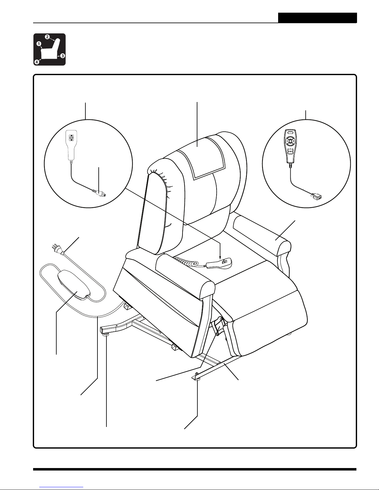
III. YOUR LIFT CHAIR
BODY COMPONENTS
This section describes the features of your lift chair. Carefully review the function and location
of each item described, and note that the illustrations and option locations shown in this manual
may not reflect the type of lift chair that you own.
LIFT CHAIR SERIES
STANDARD HAND CONTROL
POWER LEAD
HEAD COVER
HEAT AND MASSAGE
HAND CONTROL
ARM COVER
EXTERNAL
TRANSFORMER
LOW VOLTAGE
CONNECTION CABLE
LEG LEVELERS (FOUR TOTAL)
Figure 3.1 Pride Lift Chair Main Components
Lift Chair Series www.pridemobility.com 9
SCISSOR
MECHANISMS
(PINCH POINT)
LIFT MECHANISM
(PINCH POINT)
Page 10

LIFT CHAIR SERIES
III. YOUR LIFT CHAIR
Lift Mechanism: Responds to the hand control commands to position the chair in the sit, recline, and stand
positions.
Leg Levelers: Manually rotate up or down in order to stabilise the chair before use (Fig. 3.2).
ROTATE THE LEG LEVELERS TO RAISE OR LOWER THE CHAIR.
Figure 3.2 Leg Levelers
Scissor Mechanisms: Extend or retract to take the
chair through the various stages of recline (Fig. 3.3).
WARNING! Pinch/Crush Points
Hazard! Be aware that the lift
mechanism and scissor
mechanisms are a pinch point on
the lift chair. Keep the following
items and similar objects clear of
these points when operating the
lift chair:
appendages
small children
pets
wires
SCISSOR
MECHANISM
(PINCH POINT)
oxygen tubes
loose items, including but not
limited to clothing and blankets
electrical power leads
Figure 3.3 Scissor Mechanism
ELECTRICAL COMPONENTS
Your Pride Lift Chair is equipped with a low voltage DC electrical system that reduces the standard household
alternating current of 100V AC - 240V AC to direct current (24/39V DC). The electrical components include the
external transformer, batteries (not included), and hand control. Keep these areas free from moisture at all times.
WARNING! Keep all electrical components free from moisture at all times to
prevent shock and/or electrical hazard.
External Transformer: Connects to a standard electrical outlet to provide power to the lift chair. The transformer is equipped with an LED indicator, which shows green when power to the transformer is on.
The external transformer may also come equipped with mounting brackets that allow the transformer to be
mounted to the wall directly under the standard electrical outlet. The screws must be mounted to the wall stud
for security. Refer to “Appendix B” for a mounting diagram.
NOTE: Pride is not responsible for damage due to improper installation.
10 www.pridemobility.com Lift Chair Series
Page 11

III. YOUR LIFT CHAIR
LIFT CHAIR SERIES
Batteries: Provide the power needed to return the lift chair to an upright or semi-upright position in the event
of a power failure. For those models equipped with a battery backup system, the batteries (not included) mu st
be installed into the external transformer. See IV. “Assembly/Disassembly.”
NOTE: The batteries will provide power for only a short period of time after power is removed
from the system, so it is important to act quickly in the event of a power failure. Engage and
hold the up/down switch on the hand control as soon as possible. Maintain a steady pressure on
the switch to avoid excessive draw from the battery and achieve the most amount of lift. Keep
in mind that the amount of lift the batteries will be able to provide is affected by user weight
and battery condition.
Hand Control: Contains the controls needed to operate the various functions of the lift chair. Refer to V.
“Operation” for more information. The hand control may be equipped with a quick-release connector, which
enables the user to detach the hand control from the chair, disabling all functions of the hand control.
Lift Chair Series www.pridemobility.com 11
Page 12

LIFT CHAIR SERIES
Your lift chair may require some assembly before initial use. It may also require disassembly to
make servicing the chair more convenient. If your lift chair is a Knock-Down (KD) model, follow
the instructions in “Lift Chair Setup.” If your lift chair is not a KD model, proceed to “Lift Chair
Placement.”
LIFT CHAIR SETUP
KD models will arrive in the knock-down position (Fig. 4.1).
IV. ASSEMBLY/DISASSEMBLY
Figure 4.1 Knock-Down (KD) Position
Follow these steps to assemble the lift chair:
4.1.1 Remove the packaging from the back portion
of the chair and check that the locking clip is in
the vertical position. Reposition if necessary.
4.1.2 Drape the hand control and cable over the
chair base, then slide the left and right KD
sleeves of the chair-back onto the KD connections on the arms and seat of the chair.
NOTE: Depending on chair width, you may need to slide on one side of the chair-back at a time.
If this is the case, level the chair-back before pressing down to lock into position.
12 www.pridemobility.com Lift Chair Series
Page 13

HEAT CONNECTION
TO JUNCTION BOX
MASSAGE UNIT
IV. ASSEMBLY/DISASSEMBLY
LIFT CHAIR SERIES
“CLICK”
4.1.3 Push firmly on the top of the chair-back to
lock into position. Listen for a click on each
side to ensure the chair-back is locked in
properly.
NOTE: Pull up on the chair-back to ensure that
it is locked in place. If the back can be pulled
off, then repeat steps 4.1.1 and 4.1.3. You
must hear a click from each side of the chair.
MASSAGE
UNIT
JUNCTION
BOX
4.1.4 Connect the hand control harness to the
motor. For units equipped with heat and/or
massage, connect the hand control harness
directly to the junction box mounted to the
back of the lift chair.
4.1.5 For units equipped with heat and/or massage
options, connect the heat and/or massage
harnesses to the junction box mounted to the
back of the lift chair. There will be one heat
connection and two massage connections.
Lift Chair Series www.pridemobility.com 13
4.1.6 Attach the chair-back to the hook and loop
flaps on the bottom of the chair base.
Page 14

LIFT CHAIR SERIES
IV. ASSEMBLY/DISASSEMBLY
LIFT CHAIR PLACEMENT
Your lift chair should be placed near a standard electrical outlet on dry, level ground where there is ample
room to allow for proper operation. Pride recommends that you have the assistance of an attendant when
positioning the lift chair to avoid the possibility of injury when lifting.
Follow these steps to position the lift chair in a safe manner:
1. Place the back of the lift chair 76 cm (30 in.) from the nearest obstruction while the chair is in the seated
position. This measurement may vary depending on model.
2. Adjust the leg levelers to stabilise the lift chair (Fig. 3.2).
3. Install the batteries into the external transformer if applicable. Refer to “Battery Installation” for more
information.
4. Position the external transformer on the floor in an open, well-ventilated area where it will not be an
obstruction, or if equipped, utilise the optional wall mount.
5. Position the low voltage connection cable where it will not be pinched between the frame and the lift
mechanism.
6. Connect the low voltage connection cable to the external transformer if it is not already connected.
7. Plug the power lead directly into the electrical outlet. Do not use an extension lead!
NOTE: If you discover a problem at any point during the setup and positioning of your lift chair,
stop and contact your authorised Pride Provider immediately. To avoid personal injury and/or
product damage, do not plug the unit into the electrical outlet until the problem is corrected and
do not attempt to fix electrical problems by yourself
.
BATTERY INSTALLATION
Your lift chair may be equipped with a battery backup system that will activate durin g a power failure. The backup
system is powered by two 9V batteries (not included) that need to be installed into the external transformer.
Follow these steps to install the batteries:
1. Unplug the external transformer power lead from
the electrical outlet.
2. Open the marked battery door on the external
transformer.
3. Install two 9V batteries into the external transformer (Fig. 4.2).
4. Replace the battery door.
NOTE: Always make sure the external transformer is equipped with two fresh 9V batteries,
since the battery backup system does not
recharge itself. Fresh batteries are defined as
9V alkaline batteries that are replaced every
time the battery backup system is activated
during a power failure, or once a year if the battery backup system has not been activated.
NOTE: If you unplug your lift chair for an
extended period of time (more than one hour),
remove the batteries from the external transformer. The lift chair will draw power from the
batteries even when it is not in use
.
BATTERY DOOR
POWER LEAD
EXTERNAL TRANSFORMER
(TOP AND BOTTOM VIEW)
14 www.pridemobility.com Lift Chair Series
Figure 4.2 Lift Chair Battery Backup Location
Page 15

MASSAGE
UNIT
IV. ASSEMBLY/DISASSEMBLY
HEAT CONNECTION
TO JUNCTION BOX
LIFT CHAIR SERIES
LIFT CHAIR DISASSEMBLY
The back portion of KD Lift Chairs can be removed to make service a nd transport of the chair more convenient.
Follow these steps to disassemble the lift chair:
MASSAGE
UNIT
JUNCTION
BOX
4.3.1 Remove the bottom of the back fabric from
the hook and loop flaps on the chair base.
4.3.2 For units equipped with heat and/or massa ge
options, disconnect the heat and massage
connectors from the junction box.
4.3.3 Using a large flat-head screwdriver, lift the
left and right locking clips on the chair-back
one side at a time to raise the back from the
connections on the chair base. As you lift
each locking clip, pull up on the chair-back to
lift that side over the lock.
Lift Chair Series www.pridemobility.com 15
4.3.4 Lift the chair-back up and away from the
chair base.
Page 16

LIFT CHAIR SERIES
V. OPERATION
OPERATION PRECAUTIONS
There are certain precautions that should be taken during the operation of your lift chair. Read and
follow these precautions carefully in order to ensure safe lift chair operation and to prevent injury
and/or product damage.
Plug the power lead directly into the electrical outlet. Do not use an extension lead!
Do not place anything (for example, a drinking glass) on top of or near the external transformer.
If the external transformer box or hand control requires cleaning, unplug the power lead from the electri-
cal outlet and use a clean, dry cloth or lightly dampened cloth. Allow ample drying time before plugging
the power lead back into the electrical outlet.
Periodically check the hand control and all power leads for visible damage.
Keep the hand control away from all heated surfaces.
Ensure the hand control is out of the way before sitting in the chair.
Keep children and pets away from all moving parts while operating the lift chair.
Do not allow children to play on or operate the lift chair. Only the intended user should operate the lift chair.
Keep the hand control locked or utilise the quick-disconnect feature on the standard hand control when
the lift chair is not in use to prevent unintended operation of the chair.
Avoid pinch points, such as the lift and scissor mechanisms. Keep hands and feet clear of these areas.
Always leave the lift chair in an upright and closed position when not in use.
Do not sit or stand on the footrest.
Do not “drop” into the lift chair when sitting if it is in a partially raised position.
PROHIBITED! Do not place objects under the lift chair. Make sure area is clear of
obstructions, including pets and small children during operation.
WARNING! Prevent the risk of electrical shock, fire, falls, and/or being pinched.
Follow all instructions and precautions provided.
WARNING! Prevent potential equipment damage! Do not place the external
transformer under the lift chair.
WARNING! Do not cover the external transformer. Keep the transformer in an open,
well-ventilated area free from foreign material/debris to ensure proper operation.
HAND CONTROL OPERATION
Depending on lift chair model, the hand control may be
equipped with switches that control the movement of the
chair-back, chair base, and footrest, as well as the heat and
massage options (Fig. 5.1, 5.2, and 5.3).
WARNING! Do not lean on or apply
downward force to the chair-back when
the lift chair is in the fully reclined
position. Doing so could cause the lift
chair to tip, resulting in personal injury
and/or product damage.
UP
POSITION
DOWN
POSITION
WARNING! Do not use the footrest as a
seat, or for purposes outside its
intended use. Doing so could cause
instability in the lift chair and place
undue stress on lift chair components,
resulting in personal injury and/or
product damage.
WARNING! Be sure to lock or
disconnect the hand control when the
lift chair is not in use.
16 www.pridemobility.com Lift Chair Series
Figure 5.1 Standard Hand Control
Page 17

RECLINE
POSITION
V. OPERATION
LIFT CHAIR SERIES
Follow these steps to sit in your lift chair (Fig. 5.1):
1. Engage and hold the up/down switch in the UP position to raise your lift chair to the standing position.
2. Back into the lift chair and sit in the centre of the seat, using the armrests for support if needed.
3. Engage and hold the up/down switch in the DOWN position to lower the lift chair to a comfortable seated
position.
Follow these steps to recline your lift chair from the seated position (Fig. 5.1):
1. Engage and hold the up/down switch in the DOWN position until comfortably reclined.
2. Engage and hold the up/down switch in the UP position to return to an upright, seated position. Release
the switch when the lift chair reaches a comfortable seated position.
Follow these steps to stand up from your lift chair (Fig. 5.1):
1. Engage and hold the up/down switch in the UP position to raise your lift chair.
2. Release the switch when the lift chair reaches a height where you can stand up comfortably.
Dual Motor Hand Control Operation (LL660)
Follow these steps to sit in your lift chair (Fig. 5.2):
1. Slide the inhibit switch to the left.
2. Engage and hold the up/down switch in the UP position
to raise your lift chair from the seated position to the
standing position.
3. Back into the lift chair and sit in the center of the seat,
using the armrests for support if needed.
4. Engage and hold the up/down switch in the DOWN position to lower the lift chair to a comfortable seated position.
DOWN
POSITION
LIFT
POSITION
UP
POSITION
Follow these steps to recline your lift chair from the
seated position (Fig. 5.2):
INHIBIT
SWITCH
1. Slide the inhibit switch to the right.
2. Engage and hold the up/down switch in the DOWN position until comfortably reclined.
3. Engage and hold the up/down switch in the UP position
to return to an upright, seated position. Release the
switch when the lift chair reaches a comfortable seated
position.
Figure 5.2 Dual Motor Hand Control (LL660)
Follow these steps to raise or lower the footrest while in the seated or reclined position (Fig. 5.2):
1. Slide the inhibit switch to the left.
2. Engage and hold the up/down switch in the DOWN position until the footrest is fully elevated.
3. Engage and hold the up/down switch in the UP position to lower the footrest.
Follow these steps to stand up from your lift chair from the seated position (Fig. 5.2):
1. Slide the inhibit switch to the left.
2. Engage and hold the up/down switch in the UP position to raise your lift chair.
3. Release the switch when the lift chair reaches a height where you can stand up comfortably.
Follow these steps to recline your LL770 Lift Chair to the “Trendelenburg” position from the seated
position (Fig. 5.2):
NOTE: The “Trendelenburg” position is designed to elevate the legs above the head
Lift Chair Series www.pridemobility.com 17
.
Page 18

LIFT CHAIR SERIES
V. OPERATION
1. Slide the inhibit switch to the left.
2. Engage and hold the up/down switch in the DOWN position until the footrest is fully elevated.
3. Slide the inhibit switch to the right.
4. Engage and hold the up/down switch in the DOWN position until the seatback is fully reclined.
5. Engage and hold the up/down switch in the UP position to return to an upright, seated position. Release
the switch when the lift chair reaches a comfortable seated position.
6. Slide the inhibit switch to the left.
7. Engage and hold the up/down switch in the UP position to lower the footrest.
Follow these steps to recline your LL770 Lift Chair to the “zero gravity” position from the seated
position (Fig. 5.2):
NOTE: The “zero gravity” position is designed to disperse body weight evenly across the chair
while raising the user’s legs above the torso.
1. Slide the inhibit switch to the left.
2. Engage and hold the up/down switch in the DOWN position until the footrest is fully elevated.
3. Slide the inhibit switch to the right.
4. Engage and hold the up/down switch in the DOWN position to recline the seatback until your body
reaches a “V-like” position with your legs elevated higher from the ground than your torso.
5. Engage and hold the up/down switch in the UP position to return to an upright, seated position. Release
the switch when the lift chair reaches a comfortable seated position.
6. Slide the inhibit switch to the left.
7. Engage and hold the up/down switch in the UP position to lower the footrest.
Heat and Massage Hand Control Operation
Follow these steps to sit in your lift chair (Fig. 5.3):
1. Press and hold the UP button to raise your lift chair to the
HEAT BUTTON
UP BUTTON
LOCK/UNLOCK
BUTTON
standing position.
2. Back into the lift chair and sit in the centre of the seat,
using the armrests for support if needed.
3. Press and hold the DOWN button to lower the lift chair to
a comfortable seated position.
Follow these steps to recline your lift chair from the
seated position (Fig. 5.3):
1. Press and hold the DOWN button until comfortably
reclined.
2. Press and hold the UP button to return to an upright,
seated position. Release the button when the lift chair
reaches a comfortable seated position.
UNLOCK
LED
MASSAGE
SETTING
LEDS
MASSAGE
BUTTON
LOCK LED
DOWN BUTTON
INTENSITY
SETTING
LEDS
INTENSITY
BUTTON
Follow these steps to stand up from your lift chair (Fig. 5.3):
1. Press and hold the UP button to raise your lift chair.
2. Release the button when the lift chair reaches a height
where you can stand up comfortably.
Figure 5.3 Heat and Massage Hand
Control
Follow these steps to activate/deactivate the lock feature (Fig. 5.3):
1. Press and hold the LOCK button for approximately 3 seconds to lock the hand control. The red LED to
the right of the button will light up to indicate the hand control has been locked.
2. Press and hold the LOCK button for approximately 6 seconds to unlock the hand control. The green LED
to the left of the button will light up to indicate the hand control has been unlocked.
18 www.pridemobility.com Lift Chair Series
Page 19

V. OPERATION
LIFT CHAIR SERIES
Follow these steps to operate the heat function (Fig. 5.3):
1. Press the HEAT button once to activate the heat function. The heat function will shut off automatically
after 20 minutes of continuous use.
2. Press the HEAT button again to turn off the heat function.
Follow these steps to operate the massage option (Fig. 5.3):
1. Press the MASSAGE button once to activate the massage function. This will automatically set the massage to the wave setting.
2. Press the MASSAGE button again to go to the next of three available massage settings: wave, steady, or
pulse. Each press of the button w ill take you to the next setting. Each setting is indicated by a c oloured LED.
3. Press and hold the MASSAGE button for approximately 2 seconds to shut off the massage function,
otherwise this function will shut off automatically after 20 minutes of continuous use.
Follow these steps to adjust the intensity of the massage function (Fig. 5.3):
1. Press the INTENSITY button once to set the massage option to low.
2. Press the INTENSITY button again to set the massage option to the next of three available settings: low,
medium, or high. Each press of the button will take you to the next setting. Each setting is indicated by a
coloured LED.
NOTE: All heat units are designed with an auto-shutoff mechanism that turns off the heat after
20 minutes of use. Pride recommends that the heat and massage units not be used for more than
20 minutes at a time. However, you should consult your physician about how often you should
use the heat and massage options on your lift chair.
Lift Chair Series www.pridemobility.com 19
Page 20

LIFT CHAIR SERIES
Your Pride Lift Chair is a state-of-the-art product designed to enhance your mobility. Your lift chair
should bring you years of trouble-free service, however, it may require occasional troubleshooting. The following troubleshooting tips and FAQs should summarise what you need t o know about
your lift chair. If at any time you do not feel comfortable performing the troubleshooting steps listed
in this manual, contact your authorised Pride Provider for service. Please have the model number,
serial number, and nature of the problem when calling.
VI. TROUBLESHOOTING
FREQUENTLY ASKED QUESTIONS
What if my lift chair does not operate at all?
Ensure the external transformer is plugged into a properly wired electrical outlet.
Check the circuit breaker box connected to the electrical outlet to ensure the outlet is receiving power.
Ensure the low voltage connection cable is plugged into the external transformer.
Ensure that all cables are connected properly.
What if my lift chair operates in one direction only?
Check the up and down buttons on the hand control to make sure the buttons do no t st ick. If the b uttons
are sticking in either position, the hand control may need to be replaced.
Contact your authorised Pride Provider for further assistance.
What if my lift chair stops during a lifting cycle?
Your lift chair is equipped with an internal thermal shutoff switch located inside the external transformer
that prevents the motor control box from overheating. If the thermal shutoff activates, allow the lift chair
to remain in a stationary position for 10 minutes to allow the motor to cool, then resume normal operation.
If you notice the motors overheating frequently, contact your authorised Pride Provider.
There may have been a power failure and/or there are no batteries in the external transformer or the
batteries have no charge. Always make sure there are fresh 9V batteries in the external transformer if
equipped with battery backup.
Check the circuit breaker box connected to the electrical outlet to ensure the outlet is receiving power.
What if the heat and massage options on my lift chair do not function?
Ensure the junction box is connected properly to the external transformer and that there is power to the
transformer. A green LED will light on the transformer to indicate power.
Ensure the heat and massage units are connected properly to the junction box at the rear of the lift chair.
Ensure the hand control is connected properly to the junction box. If connected properly, the LEDs on the
hand control will be lit.
If any of the LEDs do not light, contact your authorised Pride Provider for further assistance.
What if my lift chair is rocking from corner to corner after I position the chair?
The floor may be uneven or the carpet may be affecting chair position. Adjust the leg levelers in the area
where the chair is rocking. See III. “Your Lift Chair” for instructions on leveling your chair.
Where can I place the external transformer box?
On the floor away from heat sources in an open, well-ventilated area where it will not be an obstruction.
On the wall away from heat sources utilising the optional external transformer wall mount. Refer to
“Appendix B.”
20 www.pridemobility.com Lift Chair Series
Page 21

VI. TROUBLESHOOTING
LIFT CHAIR SERIES
Where do I find the serial number on my lift chair?
You can find the serial number in two locations—one is near the rear of the motor on the steel lift mechanism,
the second is attached to the frame below the scissor mechanisms. The model number for your lift chair is
printed below the serial number bar code.
Who do I call for service?
Contact your authorised Pride Provider for service.
Lift Chair Series www.pridemobility.com 21
Page 22

LIFT CHAIR SERIES
VII. CARE AND MAINTENANCE
Your Pride Lift Chair will require routine maintenance checks. You can perform some of these
checks, but others may require assistance from an authorised Pride Provider. By following the
maintenance checks in this section as scheduled, you can help ensure your lift chair gives you
years of trouble-free operation. If you have any questions regarding your lift chair’s care, contact
your authorised Pride Provider.
FABRIC CARE
Inspect the fabric on a regular basis for any pulls, tears, or gaps.
Your lift chair fabric is made of 100% polyester and falls under cleaning code W. Frequent vacuuming and
light brushing to remove dust and grime is the recommended cleaning method for your lift chair. If spot
cleaning is required, you should use the foam from water-based cleaning agents such as mild detergent
or non-solvent upholstery shampoo. Apply the foam with a soft brush in a circular motion and vacuum
when dry. Pretest a small area of the fabric with the cleaning agent before using this method. If your lift
chair fabric is in an overall soiled condition, use a professional furniture-cleaning service.
WARNING! Fabric should not be allowed to come in direct contact with any type of
heat source, e.g., a space heater or cigarette. Personal injury or fire damage may
occur.
WARNING! Pride strongly recommends that you do not smoke cigarettes while
seated in or using your lift chair, although the lift chair has passed the necessary
testing requirements for cigarette smoking. You must adhere to the following
safety guidelines if you decide to smoke cigarettes while seated in or using your lift
chair.
Do not leave lit cigarettes unattended.
Keep ashtrays a safe distance from the lift chair.
Always make sure cigarettes are completely extinguished before disposal.
NOTE: Do not use solvent-type cleaners to spot clean. Do not saturate the fabric. Prevent damage
to the fabric; do not expose the lift chair to direct sunlight
.
ELECTRONICS CARE
Inspect all wiring harnesses to make sure they are not damaged or frayed.
If damage is present, unplug the lift chair and contact your authorised Pride Provider for service.
Keep all electronics free from moisture and temperature extremes. Pride Lift Chairs are intended for
indoor use only!
WARNING! Even though the lift chair has passed the necessary testing
requirements for ingress of liquids, you should keep electrical connections away
from sources of dampness, including direct exposure to water or bodily fluids and
incontinence. Check electrical components frequently for signs of corrosion and
replace as necessary.
DISPOSAL AND RECYCLING
Your lift chair must be disposed of according to applicable local and national statutory regulations. Contact
your local waste disposal agency or authorised Pride Provider for information on proper disposal of lift chair
packaging, metal frame components, fabric, electronic components, and batteries.
WARNING! Plastic bags are a suffocation hazard. Dispose of plastic bags properly
and do not allow children to play with them.
22 www.pridemobility.com Lift Chair Series
Page 23

VIII. WARRANTY
LIFT CHAIR SERIES
TWO-YEAR LIMITED WARRANTY
For two (2) years from the date of purchase, Pride will repair or replace at our option to the
original purchaser any of the following parts found upon examination by an authorised
representative of Pride to be defective in material and/or workmanship:
Steel Frame Motor Hand Control Scissor Mechanisms
Scissor Lift Mechanism
NOTE: Pride reserves the right to replace only the part of the steel lift mechanism that may be
defective.
NOT COVERED UNDER WARRANTY
The following parts are classed as wear items, which may under normal wear and tear require replacing.
These items are not therefore covered under warranty: all fabric. Warranty will also be refused if damage is
deemed to have been caused through misuse or accident for which Pride Mobility Products Australia Pty. Ltd.
cannot be deemed responsible.
NOTE: Pride Mobility Products Australia Pty. Ltd provides parts only under warranty. Your Pride
Provider is responsible for labour and service. Please contact your Pride Provider for information
about these services and for any applicable charges.
Lift Chair Series www.pridemobility.com 23
Page 24

LIFT CHAIR SERIES
MODEL NUMBER WEIGHT CAPACITY (RATED)
APPENDIX A
805KD
136 kg (300 lbs.)
C15KD
LC101
147 kg (325 lbs.)
LC101R
550SKD
550MKD
550LKD
560KD
570KD
170 kg (375 lbs.)
585KD
660KD
D30KD
LC900
555KD
MANDATORY! Stay within the specified weight capacity of your lift chair.
Exceeding the weight capacity voids your Pride Lift Chair warranty.
272 kg (600 lbs.)
24 www.pridemobility.com Lift Chair Series
Page 25

APPENDIX B
LIFT CHAIR SERIES
EXTERNAL TRANSFORMER OPTIONAL WALL MOUNT DIAGRAM
Cut out this diagram (1:1 scale) and use to mark area of placement for the external transformer.
Drill
Lift Chair Series www.pridemobility.com 25
Page 26

LIFT CHAIR SERIES
APPENDIX B
(This page intentionally left blank.)
26 www.pridemobility.com Lift Chair Series
Page 27

Page 28

Mobility Products Australia Pty. Ltd.
®
*INFMANU1767*
Available From
Moreton Medical Equipment
Ph: (07) 3284 2811
1/107 Anzac Ave, Redcliffe
www.moretonmedicalequipment.com.au
 Loading...