

Page 1
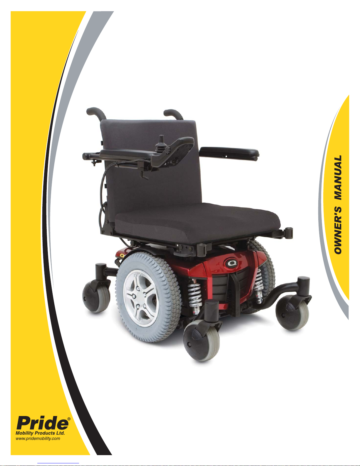
QUANTUM
610
Page 2
SAFETY GUIDELINES
WARNING! A Quantum Rehab Dealer or a qualifi ed technician must perform the initial setup of
this power chair and must perform all of the procedures in this manual.
The symbols below are used throughout this owner’s manual and on the power chair to identify warnings and
important information. It is very important for you to read them and understand them completely.
WARNING! Indicates a potentially hazardous condition/situation. Failure to follow designated
procedures can cause either personal injury, component damage, or malfunction. On the
product, this icon is represented as a black symbol on a yellow triangle with a black border.
MANDATORY! These actions should be perfor med as specifi ed. Failure to perform mandatory
actions can cause personal injury and/or equipment damage. On the product, this icon is
represented as a white symbol on a blue dot with a white border.
PROHIBITED! These actions are prohibited. These actions should not be performed at any
time or in any circumstances. Performing a prohibited action can cause personal injury and/or
equipment damage. On the product, this icon is represented as a black symbol with a red circle
and red slash.
INTENDED USE
The intended use of the Pride Mobility Products device is to provide mobility to persons limited to a seated
position that have the capability of operating a powered wheelchair.
Quick Reference Information:
Quantum Rehab Dealer:
Address:
Phone Number:
Purchase Date:
NOTE: This owner’s manual is compiled from the latest specifi cations and product information available at
the time of publication. We reserve the right to make changes as they become necessary. Any changes to our
products may cause slight variations between the illustrations and explanations in this manual and the product
you have purchased. The latest/current version of this manual is available on our website.
NOTE: This product meets IPX4 classifi cation (IEC 60529).
NOTE: This product is compliant with WEEE, RoHS and REACH directives and requirements.
NOTE: The Quantum 610 and its components are not made with natural rubber latex. Consult with the
manufacturer regarding any after-market accessories.
Copyright © 2015
INFMANU3077/Rev D/September 2015
Page 3

CONTENTSCONTENTS
I. INTRODUCTION ...................................................................................................................................4
II. SAFETY ....................................................................................................................................................5
III. YOUR POWER CHAIR ........................................................................................................................7
IV. ASSEMBLY ............................................................................................................................................11
V. COMFORT ADJUSTMENTS ..........................................................................................................14
VI. BATTERIES AND CHARGING ......................................................................................................20
VII. CARE AND MAINTENANCE ..........................................................................................................24
Quantum 610 www.pridemobility.com 3
Page 4

I. INTRODUCTION
SAFETY
WELCOME to Quantum Rehab. The power chair you have purchased combines state-of-the-art components with
safety, comfort, and styling in mind. We are confi dent that these design features will provide you with the con-
veniences you expect during your daily activities. Once you understand how to safely operate and care for your
power chair, it should give you years of trouble-free operation and service.
Read and follow all instructions, warnings, and notes in this manual before attempting to operate your power
chair for the fi rst time. You must also read all instructions, warnings, and notes contained in any supplemental
instructional booklets for the controller, front riggings, and/or seating system that accompanied your power chair
before initial operation. Your safety depends upon you, as well as your dealer, carer, or healthcare professional in
using good judgment.
If there is any information in this manual which you do not understand, or if you require additional assistance for
setup or operation, please contact your Quantum Rehab Dealer. Failure to follow the instructions in this man-
ual and those located on your power chair can lead to personal injury and/or damage to the power chair,
including voiding the warranty.
PURCHASER’S AGREEMENT
By accepting delivery of this product, you promise that you will not change, alter, or modify this product or remove or render inoperable or unsafe any guards, shields, or other safety features of this product; fail, refuse, or
neglect to install any retrofi t kits from time to time provided by Quantum Rehab to enhance or preserve the safe
use of this product.
SHIPPING AND DELIVERY
Before using your power chair, make sure your delivery is complete as some components may be individually
packaged. If you do not receive a complete delivery, please contact your Quantum Rehab Dealer immediately.
Where damage has occurred during transport, either to the packaging or content, please contact the delivery com-
pany responsible.
United Kingdom
Pride Mobility Products Ltd
32 Wedgwood Road
Bicester, Oxfordshire OX26 4UL
UK
NOTE: If you ever lose or misplace your copy of this manual, contact us and we will be glad to send you a new
one immediately.
4 www.pridemobility.com Quantum 610
Page 5
II. SAFETY
PRODUCT SAFETY SYMBOLS
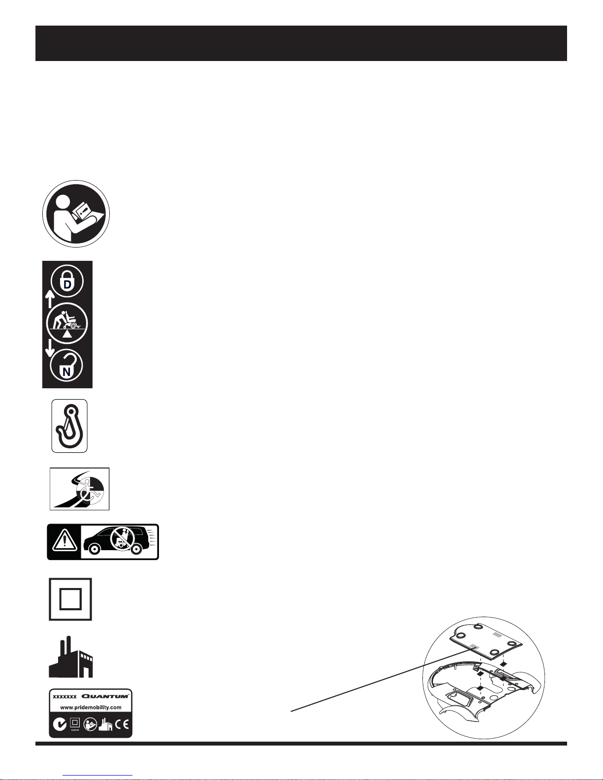
The symbols below are used on the power chair to identify warnings, mandatory actions, and prohibited actions.
It is very important for you to read and understand them completely.
NOTE: There are more warnings identifi ed and explained in the Consumer Safety Guide that is included with
your power chair. Please become familiar with all the warnings and safety information found in the Consumer
Safety Guide and refer to this resource often.
Read and follow the information in the owner’s manual.
Locked and in drive mode.
Place unit on level ground and stand to one side when changing from drive mode to
freewheel mode or freewheel mode to drive mode.
Unlocked and in freewheel mode.
Indicates power chair securement points.
Indicates that power chair, with similarly labeled seating system, conforms to ISO
7176-19 for transport of an occupied power chair in a motor vehicle.
Indicates that power c hair with a similar label is not rated for occupied transit.
Class II Equipment
Manufactured in
Power chair information label
Quantum 610 www.pridemobility.com 5
Page 6

II. SAFETY
GENERAL GUIDELINES
MANDATOR Y! Do not operate your new po wer chair f or the fi rst time without completely reading
and understanding this owner’s manual.
Your power chair is a state-of-the-art life-enhancement device designed to increase mobility. Quantum Rehab provides
an extensive variety of products to best fi t the individual needs of the power chair user. Please be aware that the fi nal
selection and purchasing decision regarding the type of power chair to be used is the responsibility of the power chair
user, who is capable of making such a decision, and his/her healthcare professional (i.e., medical doctor, physical
therapist, etc.).
The contents of this manual are based on the expectation that a mobility device expert has properly fi tted the
power chair to the user and has assisted the prescribing healthcare professional and/or the Quantum Rehab Dealer
in the instruction process for the use of the product.
There are certain situations, including some medical conditions, where the power chair user will need to practice
operating the power chair in the presence of a trained attendant. A trained attendant can be defi ned as a family
member or care professional specially trained in assisting a power chair user in various daily living activities.
As you begin using your power chair during daily activities, you will probably encounter situations in which
you will need some practice. Simply take your time and you will soon be in full and confi dent control as you
manoeuvre through doorways, on and off of lifts, up and down ramps and over moderate terrain.
Below are some precautions, tips, and other safety considerations that will help you become accustomed to
operating your power chair safely.
Pre-Ride Safety Check
Get to know the feel of your power chair and its capabilities. Quantum Rehab recommends that you perform a
safety check before each use to make sure your power chair operates smoothly and safely.
Perform the following inspections prior to using your power chair:
■ Check for proper tyre infl ation. Maintain but do not exceed the psi/bar/kPa air pressure rating indicated on
each tyre if equipped with pneumatic tyres.
■ Check all electrical connections. Make sure they are tight and not corroded.
■ Check all controller connections to the power base. Make sure they are secured properly.
■ Check the brakes. See VII. “Care and Maintenance.”
■ Check battery charge. See VI. “Batteries and Charging.”
■ Ensure the manual freewheel levers are in drive mode before sitting on the power chair.
NOTE: If you discover a problem, contact your Quantum Rehab Dealer for assistance.
6 www.pridemobility.com Quantum 610
Page 7
III. YOUR POWER CHAIR
THE QUANTUM 610
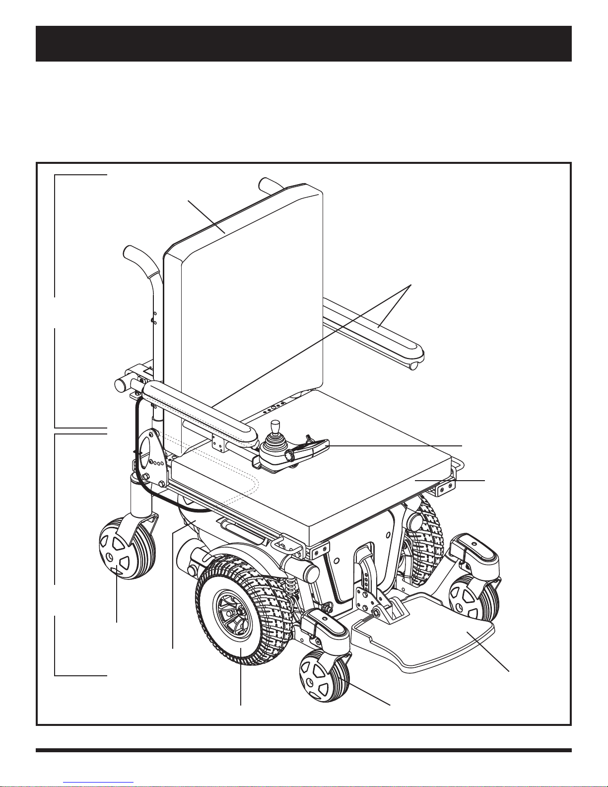
The Quantum 610 has two main assemblies: the seat assembly and the power base assembly. See fi gure 1.
Typically, the seat assembly includes the armrests, seatback and seat base. The power base assembly includes two
motor/brake assemblies, two drive wheels, four castor wheels, two batteries and wiring harnesses. See fi gure 1,
2 and 3.
SEATBACK
ARMRESTS
SEAT
ASSEMBLY
POWER BASE
ASSEMBLY
CASTOR WHEEL
REAR SHROUD
DRIVE WHEEL
CONTROLLER
SEAT BASE
FRONT RIGGING
(FOOT PLATFORM SHOWN)
CASTOR WHEEL
Figure 1. The Quantum 600 Sport
Quantum 610 www.pridemobility.com 7
Page 8
III. YOUR POWER CHAIR
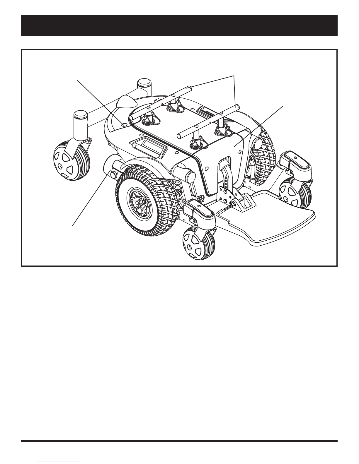
REAR SHROUD FASTENER
MOTOR/BRAKE ASSEMBL Y
TRAPEZE BARS
FRONT COVER
Figure 2. The Quantum 610 Series Power Base
Electrical Components
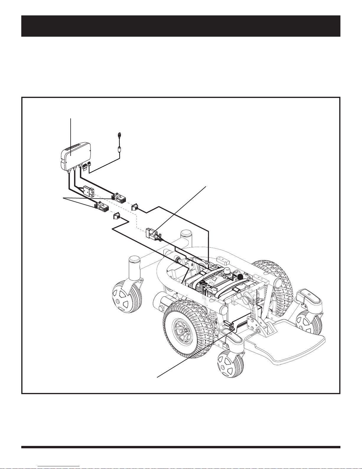
The electrical components are located inside the power base. The main circuit breaker is located on the front of
the battery tray. The controller connector(s) are located inside the power base. See fi gure 3.
Motor Connectors: This is where the controller connects to the motors.
Battery Connector: This is where the controller connects to the batteries.
Controller Connector: This is where the controller connects to the power base. Each controller uses a different
type of harness. Regardless of which type of controller is used, the harness must be secured to the seat assembly
and not allowed to drag on the fl oor.
8 www.pridemobility.com Quantum 610
Page 9
III. YOUR POWER CHAIR
Main Circuit Breaker: The main circuit breaker is a safety feature built into your power chair. When the batteries
and the motors are heavily strained (e.g., from excessive loads), the main circuit breaker trips to prevent damage
to the motors and the electronics. If the circuit trips, allow your power chair to “rest” for approximately one
minute. Next, push in the circuit breaker button, turn on the controller, and continue normal operation. If the main
circuit breaker continues to trip repeatedly, contact your Quantum Rehab Dealer.
POWER MODULE
BATTERY CONNECTOR
MOTOR
CONNECTORS
MAIN CIRCUIT BREAKER
Figure 3. Quantum 610 Series Electrical Components
Quantum 610 www.pridemobility.com 9
Page 10
III. YOUR POWER CHAIR
Manual Freewheel Levers
Your power chair has a manual freewheel lever on each motor. Manual freewheel levers enable you to disengage
the drive motors from the gearboxes and manoeuvre the chair manually.
WARNING! Do not use the power chair while the drive motors are disengaged! Do not
disengage the drive motors when the power chair is on an incline or decline, as the
unit could roll on its own! Only engage the freewheel mode when on a level surface.
WARNING! It is important to remember that when your power chair is in freewheel
mode, the braking system is disengaged.
To engage or disengage the drive motors:
1. Locate the lever on top of each motor.
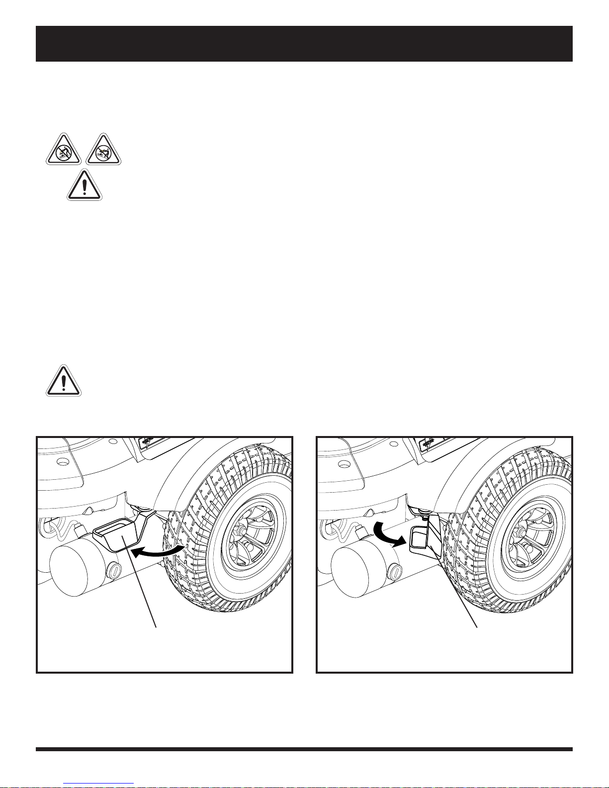
2. Push the two levers inward to engage the drive motors (drive mode). See fi gure 4.
3. Pull the two levers outward to disengage the drive motors (freewheel mode). See fi gure 5.
NOTE: If the lever is diffi cult to move in either direction, rock your power chair back and forth slightly. The
lever should then move to the desired position.
NOTE: The power chair will be signifi cantly easier to push with the power off.
WARNING! Avoid applying excessive force to the manual freewheel levers.
WARNING! Do not use your foot to operate the manual freewheel levers. Do not stand on the
manual freewheel levers. Applying excessive force to the manual freewheel levers may result in
damage to the freewheel levers, motors, and brakes.
WARNING! Do not use the freewheel lever handles as tie-down points to secure this product.
MANUAL FREEWHEEL
LEVER
MANUAL FREEWHEEL
LEVER
Figure 4. Drive Mode (Drive Engaged)
10 www.pridemobility.com Quantum 610
Figure 5. Freewheel Mode (Drive Disengaged)
Page 11
IV. ASSEMBLY
INITIAL ASSEMBLY
Your power chair may require some assembly either before initial use or after transportation. It may also require
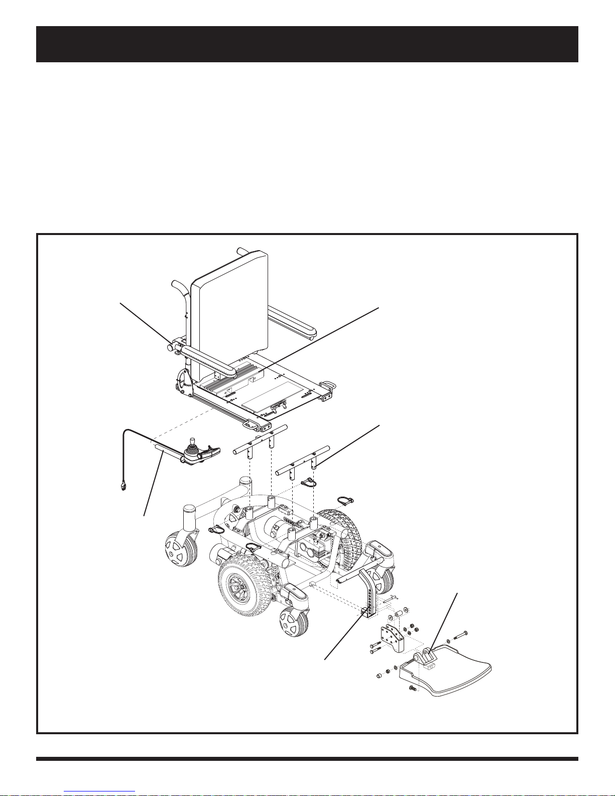
disassembly to make some comfort adjustments. Figure 6 details those parts of the power chair that are designed
to be disassembled and assembled by an end user or by a qualifi ed carer before using the product or making
comfort adjustments.
NOTE: Any nylon insert lock nut removed during the disassembly or adjustment of the power chair must be
replaced with a new nut. Nylon insert lock nuts should not be reused as it may cause damage to the nylon
insert, resulting in a less secure fi t. Replacement nylon insert lock nuts are available at local hardware stores
or through your Quantum Rehab Dealer.
ARMREST ANGLE ADJUSTMENT
CONTROLLER POSITION
SEAT INSTALLATION
SEAT HEIGHT/ANGLE ADJUSTMENT
FOOT PLATFORM
ANGLE ADJUSTMENT
FOOT PLATFORM HEIGHT/DEPTH ADJUSTMENT
Figure 6. Quantum 610 Series Assembly View (Universal Mounting System Shown)
Quantum 610 www.pridemobility.com 11
Page 12
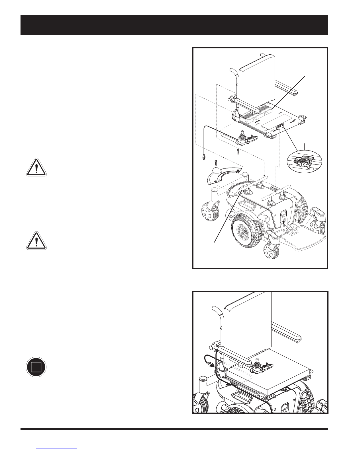
IV. ASSEMBLY
Seat Installation
It may be necessary to install the seat either prior to initial
operation or after transporting your power chair. Most
seats are attached to the power base with the Universal
Mounting System (UMS). The UMS consists of universal
parts that may be attached to any medium-back or high-back
seat, regardless of seat width or seat depth. The two main
components are aluminum extrusions mounted to the seat
base. These extrusions attach to a pair of trapeze bars that are
mounted to the power base. See fi gure 7.
REAR
EXTRUSION
NOTE: If your power chair is equipped with a Synergy
Seat, or a TRU-Balance
®
Power Positioning System, refer
to the information provided in separate manuals.
WARNING! Do not pick up the seat frame by
the armrests. They are free to pivot, and you
may lose control of the seat if they do so.
To install the seat:
1. Tilt the seat back and slide the rear extrusion onto the
rear trapeze bar. See fi gure 7.
2. Lower the front extrusion onto the front trapeze bar until
the seat locks into place.
3. Flip the seat latch safety down. See fi gure 7.
WARNING! Make sure the seat latch saf ety is
fl ipped down before using your power chair.
4. Install the controller and route the harness to the back of
the power base. See fi gure 8.
5. Loosen the rear shroud fasteners and remove the rear
shroud. See fi gure 2.
6. Plug the controller connector into the power base. See
fi gure 3.
7. Reinstall the rear shroud and tighten the rear shroud
fasteners. See fi gure 2.
8. Route the controller harness so that it cannot be pinched
in the seat hinge.
REAR LATCH
SAFETY
REAR TRAPEZE
BAR
Figure 7. Universal Mounting System
MANDATORY! Prevent controller harness
damage! Use correct tie-down points
for controller harness. Avoid routing the
controller harness on the outside of the
armrest pad. Route the harness under the
armrest or toward the inside of the ar mrest
pad. Use correct tie-down points for the
controller harness to prevent the harness
from getting caught in the drive tyres,
pinched in the seat frame, or damaged when
passing through doorways.
9. Secure the controller harness to the armrest receiver with
wire ties. See fi gure 9.
12 www.pridemobility.com Quantum 610
Figure 8. Controller Routed on a Synergy Seat
Page 13
IV. ASSEMBLY
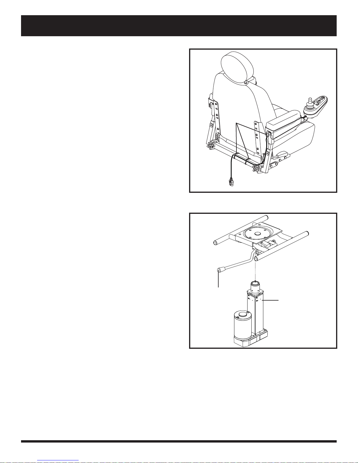
Power Seat Option Installation
Your power chair may be equipped with the power seat
option. While the seat itself may be any one of the styles
offered for this model, the way the seat base attaches to
the power base is different.
To install the power seat:
1. Align the post on the bottom of the power seat base
over the hole in the power seat actuator. See fi gure 10.
2. Slide the post into the actuator and push the friction
lock lever forward.
3. Connect the power seat cable to the power base.
4. Tilt the seat back and slide the rear extension onto the
power seat base.
5. Lower the front extrusion onto the power seat base
until the seat locks into place.
6. Flip down the seat latch safety.
7. Install the controller.
NOTE: Refer to V. “Comfort Adjustments” for more
information on controller installation and adjustment.
WIRE TIES
Figure 9. Controller Routed on a Contour Seat
Quantum 610 www.pridemobility.com 13
FRICTION LOCK
LEVER
Figure 10. Power Seat Actuator
POWER SEAT
ACTUATOR
Page 14
V. COMFORT ADJUSTMENTS
COMFORT ADJUSTMENTS
After becoming familiar with your power chair’s operation, you may fi nd the need to make some adjustments to
increase your comfort, such as seat height and angle, armrest angle, foot platform height and angle, and controller
position. If your power chair is equipped with power positioning options, refer to the information supplied in
supplemental manuals or contact your Quantum Rehab Dealer.
WARNING! The centre of gravity of your power chair was factory set to a position that meets
the needs of the demographic majority of users. Your Quantum R ehab Dealer has evaluated your
power chair and made any necessary adjustments to suit your specifi c requirements. Do not
change your seating confi guration without fi rst contacting your Quantum Rehab Dealer.
WARNING! Some power chair components are heavy. You may need assistance to lift or carr y
them. Please refer to specifi cations table for specifi c component weights before you disassemble
the power chair.
WARNING! Remove the occupant from the power chair before making any adjustments.
Y ou may need the following to make comfort adjustments:
metric/standard socket set and ratchet
adjustable spanner
thread lock
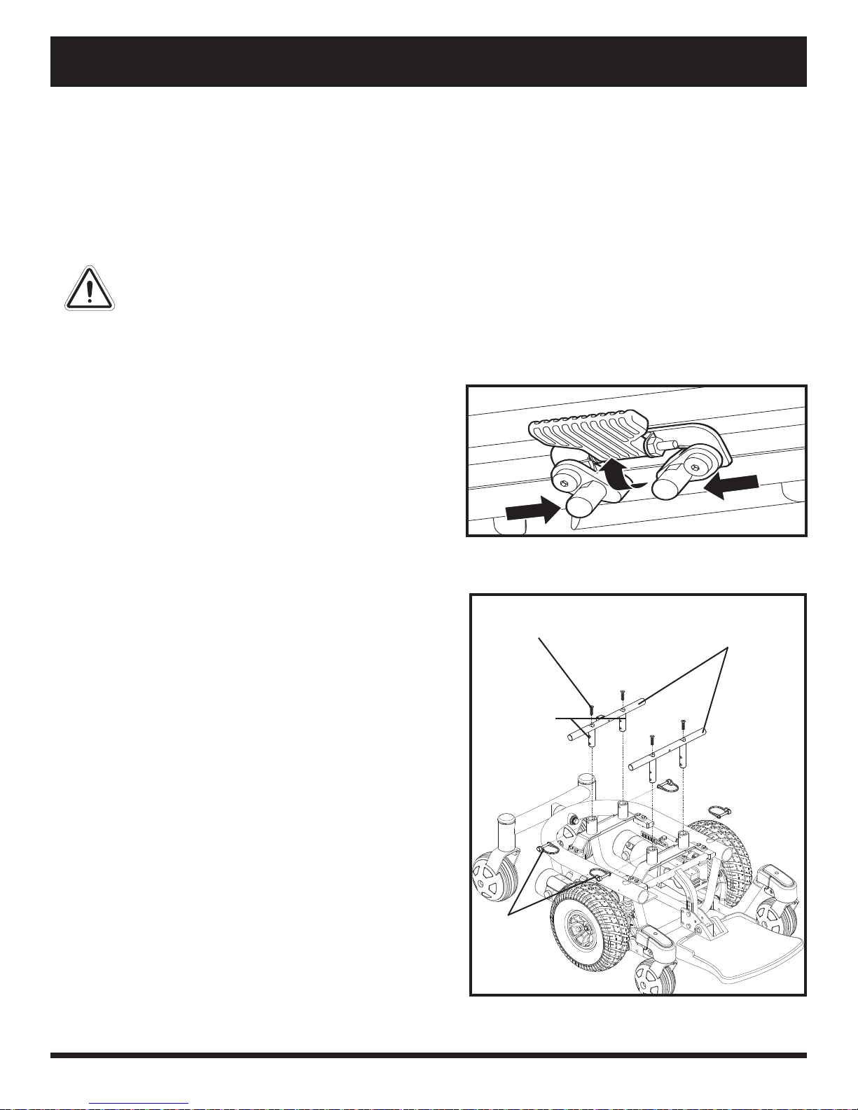
Seat Height and Seat Angle Adjustment
You can change the seat height to one of four positions in
2.54-cm (1-in.) increments by raising the front and rear
trapeze bars. If you raise or lower only one trapeze bar (front
or rear), you can also change the seat base angle (dump).
To change the seat height:
1. Turn off the power to the controller.
2. Loosen the rear shroud fasteners and remove the rear
shroud. See fi gure 2.
3. Disconnect the controller connector(s) from the power
base. See fi gure 3.
4. Flip up the seat latch safety. See fi gure 11.
5. Squeeze the seat latch and release the seat from the front
trapeze bar. See fi gure 11.
6. Slide the seat forward and remove it from the power
base.
7. Loosen the screws that attach the trapeze bars to the seat
posts. See fi gure 12.
8. Remove the retaining clips that secure the seat posts to
the power base. See fi gure 12.
9. Move the trapeze bars up or down to the desired height.
10. Reinstall the retaining clips from step 8.
11. Remove each screw from the trapeze bars and apply
thread lock.
12. Reinstall each screw into the trapeze bars and tighten.
13. Reinstall the seat and fl ip down the seat latch safety.
14. Reconnect the controller connector(s) to the power base.
15. Reinstall the rear shroud and tighten the fasteners.
Figure 11. Seat Height Adjustment - Seat Latch
Safety
SCREWS
(2 OF 4)
SEAT POSTS
(2 OF 4)
RETAINING
CLIPS
(2 OF 4)
Figure 12. Seat Height Adjustment - Trapeze Bars
TRAPEZE BARS
14 www.pridemobility.com Quantum 610
Page 15
V. COMFORT ADJUSTMENTS
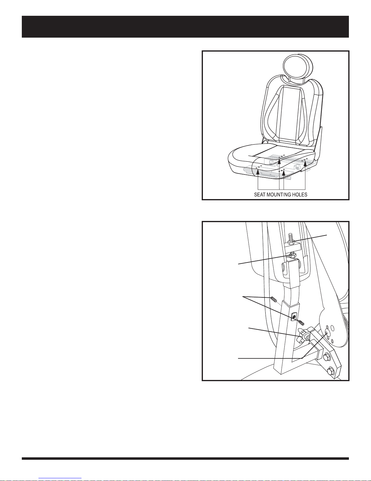
Seat Position
You can move the seat forward or rearward by changing the
extrusion mounting position.
To change the position:
1. Turn off the power to the controller.
2. Loosen the rear shroud fasteners and remove the rear
shroud. See fi gure 2.
3. Unplug the controller connector(s) from the power base.
4. Remove the seat from the power base.
5. Remove both extrusions from the bottom of the seat.
6. Reposition the extrusions on a different set of mounting
holes. You must move both extrusions the same number
of holes either forward or rearward. See fi gure 13.
7. Fasten the extrusions back onto the bottom of the seat.
8. Reinstall the seat.
9. Reconnect the controller.
10. Reinstall the rear shroud and tighten the fasteners.
Manual Recline Seatback Adjustment
If your power chair is equipped with a reclining seat, you
can adjust the seatback angle with the seatback release lever.
The lever is located on the right side of the seat base.
Figure 13. Seat Position Adjustment
LOCKING NUT
To adjust the recline angle:
1. Pull up on the seatback release lever.
2. Lean forward or rearward to the desired position.
3. Release the lever.
Seatback Angle Adjustment
If your power chair is equipped with an adjustable seatback,
you can adjust it to four (4) different angles: 90°, 102°, 105°
or 107°.
To adjust the seatback angle:
1. Remove the adjusting screws from each seat hinge. See
fi gure 14.
2. Set the seatback at the desired angle.
3. Reinstall the adjusting screws to each seat hinge and
tighten.
Armrest Width Adjustment
You can change each armrest’s width independently of the
other.
ARMREST ANGLE
ADJUSTING
SCREW
ARMREST HEIGHT
ADJUSTMENT
SETSCREW
ARMREST KNOB
SEATBACK
ANGLE
ADJUSTING
SCREW
Figure 14. Seatback Angle Adjustment
NOTE: Changing the armrest width may increase the
overall width of your power chair.
Quantum 610 www.pridemobility.com 15
Page 16
V. COMFORT ADJUSTMENTS
To change the armrest width:
1. Locate the two armrest knobs on each side of the armrest
receiver bracket. See fi gure 14.
2. Loosen the knobs.
3. Slide the armrests in or out to the desired width.
4. Tighten the knobs.
Armrest Angle Adjustment
To change the armrest angle:
1. Lift the armrest straight up so that it is perpendicular to
the fl oor. See fi gure 14.
2. Loosen the locking nuts.
3. Turn the adjusting screw to raise or lower the front of
the armrest.
4. Tighten the locking nuts to lock the adjusting screw into
place.
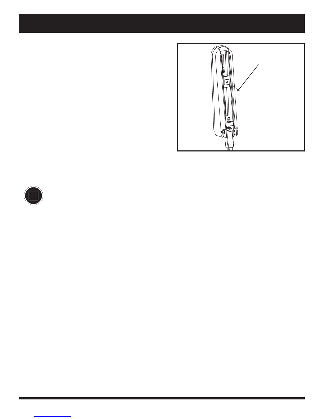
Figure 15. Underside of Armrest
Controller Position
You can move the controller in toward or out away from the armrest, or change the position of the controller for
either left-hand or right-hand use.
SCREWS
MANDATOR Y! Do not place the controller harness so that it can be pinched in the seat frame or
the power base frame.
To extend the controller:
1. Flip up the armrest so it is perpendicular to the fl oor.
2. Loosen the setscrew on the controller bracket. See fi gure 15.
3. Slide the controller into or out of the armrest to the desired position.
4. Tighten the setscrew to secure the controller.
To change the controller position:
1. Turn off the power to the controller.
2. Loosen the rear shroud fasteners and remove the rear shroud.
3. Unplug the controller connector from the power base.
4. Remove any wire ties securing the controller harness to the armrest.
5. Flip up the armrest so it is perpendicular to the fl oor.
6. Loosen the setscrew on the controller bracket
7. Slide the controller out of the armrest.
8. Loosen the setscrew in the other armrest.
9. Place the controller in the other armrest.
10. Tighten the setscrew to secure the controller.
11. Route the controller harness to the back of the power base and plug in the controller.
12. Replace the rear shroud and tighten the fasteners.
13. Secure the controller harness to the armrest with wire ties. See fi gure 9.
NOTE: If your power chair is equipped with a Synergy Seat or TRU-Balance Power Positioning System, refer
to the information provided in supplemental manuals provided with your seating system.
16 www.pridemobility.com Quantum 610
Page 17
V. COMFORT ADJUSTMENTS
Foot Platform Height Adjustment
The foot platform height is easily adjusted to different heights.
To raise or lower the foot platform:
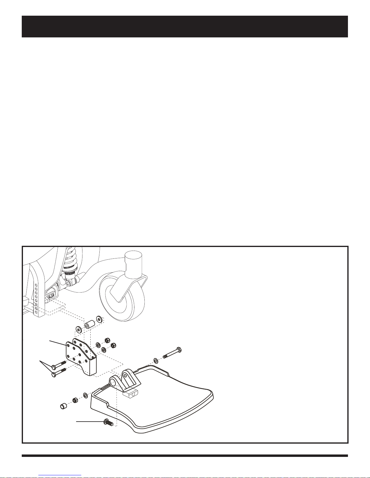
1. Remove the hardware from the foot platform bracket. See fi gure 16.
2. Raise or lower the foot platform to the desired height.
3. Reinstall the hardware into the foot platform bracket and tighten.
Foot Platform Depth Adjustment
You can adjust the depth of the foot platform.
To adjust the foot platform depth:
1. Remove the hardware from the foot platform bracket. See fi gure 16.
2. Move the foot platform in or out to the desired depth.
3. Reinstall the hardware into the foot platform bracket and tighten.
Foot Platform Angle Adjustment
You can adjust the angle of the foot platform.
To adjust the foot platform angle:
1. Flip up the foot platform and locate the screw. See fi gure 16.
2. Turn the screw to raise or lower the front of the foot platform.
FOOT
PLATFORM
BRACKET
HARDWARE
SCREW
Figure 16. Foot Platform Adjustment
Quantum 610 www.pridemobility.com 17
Page 18
V. COMFORT ADJUSTMENTS
Positioning Belt
Your power chair may be equipped with a positioning belt
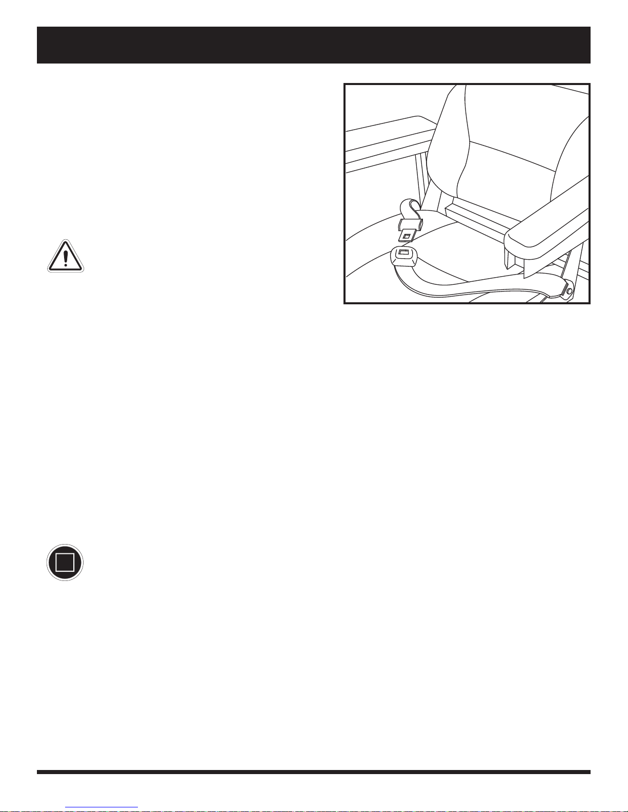
that can be adjusted for operator comfort. See fi gure 17.
The positioning belt is designed to support the operator
so that he/she does not slide down or forward in the seat.
The positioning belt is not designed for use as a restraining
device.
WARNING! The positioning belt is not
designed for use as a seat belt in a motor
vehicle. Nor is your power chair suitable
for use as a seat in any vehicle. Anyone
traveling in a vehicle should be properly
belted into seats approved by the vehicle
manufacturer.
WARNING! The positioning belt should
be secured at all times. Never allow the
positioning belt to hang or drag on the fl oor
as it may become entangled.
To install the positioning belt:
1. Remove the the rearmost screw that holds the seat hinge to the seat base on both the left and right seat hinges.
2. Insert the screw through the supplied washer, through the positioning belt, and into the seat base for each side
of the power chair.
3. Tighten both screws.
Figure 17. Positioning Belt Adjustment
To adjust the positioning belt for operator comfort:
1. Once seated, insert the metal tab on one side of the belt into the plastic housing on the opposite side until you
hear a click. See fi gure 17.
2. Pull the excess strap attached to the metal tab until it is secure, but not so tight as to cause discomfort.
To release the positioning belt:
1. Press the push button mechanism on the plastic housing.
MANDATORY! Make sure the positioning belt is properly secured to the power chair and is
adjusted for operator comfort before each use.
MANDA TOR Y! Inspect the positioning belt for loose parts or damage, including tears, worn spots,
bent hardware, damaged latch mechanisms, dirt and debris, before each use of the power chair .
If you discover a problem, contact your Quantum Rehab Dealer for maintenance and repair.
18 www.pridemobility.com Quantum 610
Page 19
V. COMFORT ADJUSTMENTS
Power Elevating Seat (Optional)
If your power chair is equipped with a power elevating seat,
you can change the seat height either through the controller
or through a toggle switch mounted to one of the armrests.
To change the seat height through toggle switch:
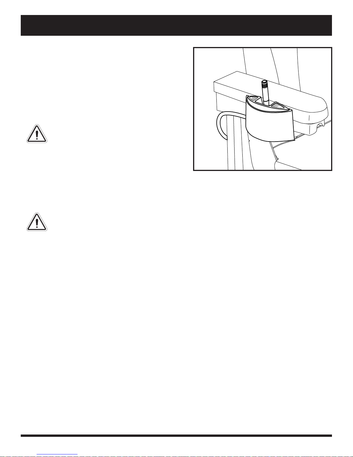
1. Press forward on the toggle switch to raise the seat. See
fi gure 18.
2. Pull back on the toggle switch to lower the seat.
WARNING! Do not allow the motor to
run more than a few seconds after the
mechanism reaches the top or bottom limit.
NOTE: For more information on operating the power
elevating seat through the controller, contact your
Quantum Rehab Dealer.
WARNING! The power elevating seat option is intended for use on a level surface only. Never
raise the seat from its lowest position on an inclined surface. Failure to heed this war ning can
result in the power chair tipping over.
Figure 18. Power Seat Toggle Switch
WARNING! Never raise the seat from its lowest position when operating your power chair on
bumpy or uneven surfaces. Failure to heed this warning can r esult in the power chair tipping
over.
WARNING! Never raise the power elevating seat while your power chair is in the freewheel
mode.
WARNING! Always fasten the positioning belt when operating the power elevating seat.
NOTE: The power elevating seat option is equipped with a system that reduces the speed of the power chair by
one half when the seat is elevated more than 2.54-5.08 cm (1-2 inches). Always check to be sure this system is
operating properly before using your power chair.
Quantum 610 www.pridemobility.com 19
Page 20

VI. BATTERIES AND CHARGING
BATTERIES AND CHARGING
The Quantum 610 uses two long-lasting, 12-volt, deep-cycle batteries. These batteries are sealed and maintenance
free. Since they are sealed, there is no need to check the electrolyte (fl uid) level. Deep-cycle batteries are designed
to handle a longer and deeper discharge. Though they are similar in appearance to automotive batteries, they are
not interchangeable. Automotive batteries are not designed to handle a long, deep discharge, and also are unsafe
for use in power chairs.
MANDA T ORY! Ba ttery posts, terminals and related accessories contain lead and lead
compounds. Wear goggles and gloves when handling batteries and wash hands after
handling.
PROHIBITED! Always use two batteries of the exact same type, chemistry , and amphour (Ah) capacity . R efer to the specifi cations table in this manual and in the manual
supplied with the battery charger for recommended type and capacities.
WARNING! Contact your Quantum Rehab Dealer if you have any questions regarding
the batteries in your power chair.
Charging the Batteries
The battery charger is essential in providing long life for your power chair batteries. It is designed to optimize your
power chair’s performance by charging the batteries safely, quickly and easily.
PROHIBITED! Removal of grounding prong can create electrical hazard. If necessary,
properly install an a pproved 3-pronged adapter to an electrical outlet having 2-pronged
plug access.
PROHIBITED! Never use an extension lead to plug in your battery charger. Plug the
charger directly into a properly wired standard electrical outlet.
PROHIBITED! Do not allow unsupervised children to play near the power chair while
the batteries are charging. Quantum Rehab recommends that you do not charge the
batteries while the power chair is occupied.
MANDATORY! Read the battery charging instr uctions in this manual and in the manual
supplied with the battery charger before charging the batteries.
WARNING! Explosive gases may be generated while charging the batteries. Keep the
power chair and battery charger away from sources of ignition such as fl ames or sparks
and provide adequate ventilation when charging the batteries.
WARNING! You must recharge your power chair’s batteries with the supplied off-board
charger. Do not use an automotive-type battery charger.
WARNING! Inspect the battery charger, wiring, and connectors for damage before each
use. Contact your Quantum Rehab Dealer if damage is found.
WARNING! Do not attempt to open the battery charger case. If the battery charger does
not appear to be working correctly, contact your Quantum Rehab Dealer.
WARNING! If the of f-board battery charger is equipped with cooling slots, then do not
attempt to insert objects through these slots.
WARNING! Be aware that the battery charger case may become hot during charging.
Avoid skin contact and do not place on surfaces that may be affected by heat.
WARNING! If your batter y charger has not been tested and approved for outdoor use,
then do not expose it to adverse or extreme weather conditions. If the battery charger
is exposed to adverse or extreme weather conditions, then it must be allowed to adjust
to the difference in environmental conditions before use indoors. Refer to the manual
supplied with the battery charger for more information.
20 www.pridemobility.com Quantum 610
Page 21
VI. BATTERIES AND CHARGING
To charge the batteries using the off-board charger:
1. Position the front of your power chair next to a standard
electrical outlet.
2. Be certain the controller power is turned off and the
freewheel levers are in the engaged position. See III.
“Your Power Chair.”
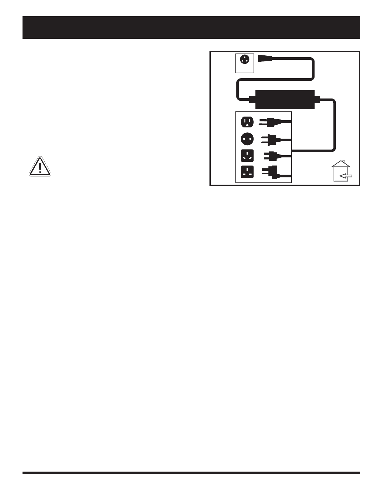
3. Plug the off-board charger into the off-board charger/
programming socket on the controller. See fi gure 19.
4. Plug the off-board charger into the electrical outlet.
WARNING! The LED lights on the charger
indicate different charger conditions at
various times: charger power on, charging in
progress, and charging complete. If the LED
does not indicate that charging is complete
within 24 hours, unplug the charger from
the outlet and contact your Quantum Rehab
Dealer. Refer to the manual supplied with
the charger for a complete explanation of
these indicators.
5. When the batteries are fully charged, unplug the offboard charger from the electrical outlet and then from
the controller.
XLR
Figure 19. Battery Charging
Battery Break-in
To break in new batteries for maximum effi ciency:
1. Fully recharge any new battery prior to its initial use. This brings the battery up to about 90% of its peak performance level.
2. Operate your power chair throughout the house and grounds. Move slowly at fi rst, and do not travel too far
until you become accustomed to the controls and break in the batteries.
3. Give the batteries another full charge of at least 8 to 14 hours and operate your power chair again. The batter-
ies will now perform at over 90% of their potential.
4. After four or fi ve charging cycles, the batteries will top off at 100% charge and last for an extended period.
Frequently Asked Questions
How does the charger work?
The battery charger takes the standard electrical outlet voltage (alternating current) and converts it to 24 VDC
(direct current). The power chair batteries use direct current to run your power chair. When the battery voltage
is low, the charger works harder to charge the battery. As the battery voltage approaches full charge, the charger
does not work as hard to complete the charging cycle. This explains why the ammeter drops as it approaches a full
charge. This is how the charger maintains a charge but does not overcharge the battery.
Can I use a different battery charger?
You should use the charger supplied with the power chair. It is the safest, most effi cient tool to charge the batteries.
We do not recommend using other types of chargers (e.g., an automotive battery charger).
NOTE: Your power chair’s charger will not operate after the batteries have been discharged to nearly zero
voltage. If this happens, call your Quantum Rehab Dealer for assistance.
Quantum 610 www.pridemobility.com 21
Page 22

VI. BATTERIES AND CHARGING
How often must I charge the batteries?
Many factors come into play when deciding how often to charge the batteries. You may use your power chair all
day on a daily basis or you may not use it for weeks at a time.
Daily Use
If you use your power chair on a daily basis, charge the batteries as soon as you are fi nished using your power
chair. Your power chair will be ready each morning to give you a full day’s service. It is recommended that
you charge the batteries at least 8 to 14 hours after daily use. Quantum Rehab recommends that you charge the
batteries for an additional 4 hours after the battery charger indicates that charging is complete.
Infrequent Use
If you use your power chair infrequently (once a week or less), you should charge the batteries at least once
per week for at least 24 hours.
NOTE: Keep your batteries fully charged and avoid deeply discharging your batteries. Refer to the manual
supplied with the battery charger for charging instructions. Quantum Rehab recommends charging your
batteries for at least 48 continuous hours once per month to improve battery performance and battery life.
How can I get maximum range or distance per charge?
Rarely do you have an ideal driving situation such as smooth, fl at, hard terrain with no wind, hills or curves. More
often you are presented with hills, pavement cracks, uneven and loosely packed surfaces, curves and wind. All of
these factors will affect the distance or running time per battery charge. Below are a few suggestions for obtaining
the maximum range per charge:
Always charge the batteries fully prior to your trip.
Plan your trip in advance to avoid inclines if possible.
Limit baggage weight to essential items.
Try to maintain an even speed and avoid stop-and-go driving.
Pride recommends charging your batteries for at least 48 continuous hours once per month to improve battery
performance and battery life.
What type of batteries should I use?
We recommend deep-cycle batteries that are sealed and maintenance free. Both AGM and Gel-Cell are deep-cycle
batteries that are similar in performance. Refer to the specifi cations for more information regarding the batteries
used with your power chair.
WARNING! Corrosive chemicals contained in batteries. Use only AGM or Gel-Cell batteries
to reduce the risk of leakage or explosive conditions.
Why do my new batteries seem weak?
Deep-cycle batteries employ a much different chemical technology than that used in car batteries, nickel-cadmium
(nicads) or in other common battery types. Deep-cycle batteries are specifi cally designed to provide power, drain
down their charge and then accept a relatively quick recharge. AGM and Gel-Cell batteries should be charged as
often as possible. They do not have a “memory” like nickel-cadmium batteries.
We work closely with our battery manufacturer to provide a battery that best suits your power chair’s specifi c
demands. Fresh batteries arrive regularly at Pride and are promptly shipped with a full charge. During shipping,
the batteries encounter temperature extremes that may infl uence initial performance. Heat robs the charge from
the battery, and cold slows the power available and extends the time needed to recharge the battery (just as with
a car battery).
22 www.pridemobility.com Quantum 610
Page 23

VI. BATTERIES AND CHARGING
It might take a few days for the temperature of the battery to stabilise and adjust to its new ambient temperature.
More importantly, it will take a few “charging cycles” (a partial drain—then a full recharge) to establish the critical chemical balance that is essential to the battery’s peak performance and long life. It will be well worth it to
take the time to break in your battery properly.
How can I ensure maximum battery life?
A fully charged deep-cycle battery will provide reliable performance and extended battery life. Keep your power
chair’s batteries fully charged whenever possible. Batteries that are regularly and deeply discharged, infrequently
charged or stored without a full charge may be permanently damaged, causing unreliable power chair operation
and limited battery life.
NOTE: The useful life of a battery is quite often a refl ection of the care it receives.
How should I store my power chair and its batteries?
If you do not use your power chair regularly, we recommend maintaining battery vitality by charging the batteries
at least once per week.
If you do not plan on using your power chair for an extended period, fully charge the batteries prior to storage.
Disconnect the battery harnesses and store the power chair in a warm, dry environment. Avoid temperature extremes, such as freezing and excessively hot conditions, and never attempt to charge a frozen battery. A cold or
frozen battery should be warmed for several days prior to recharging.
What about public transportation?
AGM and Gel-Cell batteries are designed for application in power chairs and other mobility vehicles, allowing
for safe transportation on aircraft, buses and trains, as there is no danger of spillage or leakage. We suggest you
contact the carrier’s ticket counter in advance to determine that carrier’s specifi c requirements.
What about shipping?
If you wish to use a freight company to ship your power chair to your fi nal destination, repack your power chair
in the original shipping container and ship the batteries in separate boxes.
Quantum 610 www.pridemobility.com 23
Page 24

VII. CARE AND MAINTENANCE
CARE AND MAINTENANCE
Your Quantum 610 is a sophisticated power chair. Like any motorised vehicle, it requires routine maintenance
checks. You can perform some of these checks, but others require assistance from your Quantum Rehab Dealer.
Preventive maintenance is very important. If you follow the maintenance checks in this section as scheduled, you
can help ensure that your power chair gives you years of trouble-free operation. If you have any doubt as to your
power chair’s care or operation, contact your Quantum Rehab Dealer.
WARNING! Do not service the power chair when the seat is occupied.
Your power chair, like most electrical equipment, is susceptible to damage from the elements. Avoid damp areas
of any kind.
WARNING! Direct or prolonged exposure to water or dampness could cause the power
chair to malfunction electronically and mechanically. Water can cause electrical
components to corrode and the chair’s frame to rust. Power chairs should be examined
periodically for signs of cor r osion caused by water exposure, bodily fl uids exposure, or
incontinence. Damaged components should be replaced or treated immediately.
Should your power chair come in contact with water:
1. Dry your power chair as thoroughly as possible with a towel.
2. Allow your power chair to sit in a warm, dry place for 12 hours to allow unseen water to evaporate.
3. Check the joystick operation and the brakes before using your power chair again.
4. If any inconsistencies are found, take your power chair to your Quantum Rehab Dealer. Power chairs that
are frequently exposed to sources of water, such as incontinence, should be inspected often for corrosion and
electronic components may need to be replaced frequently.
Temperature
Some of the parts of your power chair are susceptible to extreme changes in temperature. Always keep your
power chair between the temperatures of -8°C (18° F) and 50°C (122° F).
In extremely cold temperatures the batteries may freeze. The specifi c temperature at which they freeze de-
pends on a number of factors, such as battery charge, usage and composition of the batteries (e.g., AGM or
Gel-Cell).
Temperatures above 50°C (122° F) may cause your power chair to operate at a reduced speed. This reduced
speed is a safety feature built into the controller that helps prevent damage to the motor and other electrical
components.
General Guidelines
Avoid knocking or bumping the controller, especially the joystick.
Avoid prolonged exposure of your power chair to extreme conditions, such as heat, cold, or moisture.
Keep the controller clean.
Check all connectors to ensure that they are all tight and secured properly.
Make sure pneumatic drive tyres are infl ated to the psi/bar/kPa air pressure rating indicated on each tyre.
WARNING! It is critically important that the psi/bar/kPa air pressure rating on each tyre be
maintained in pneumatic tyres at all times. Do not underinfl ate or overinfl ate your tyres. Low
pressure may result in loss of control, and overinfl ated tyres may burst. Overinfl ating tyres can
cause them to explode.
WARNING! Do not use a high pressure hose to infl ate your tyres.
Use a rubber conditioner on the tyre sidewalls to help preserve them.
WARNING! Never use a rubber conditioner on the tread area of the tyres; doing so may make the
tyres slippery and cause your power chair to skid.
24 www.pridemobility.com Quantum 610
Page 25

VII. CARE AND MAINTENANCE
All wheel bearings are prelubricated and sealed. They require no subsequent lubrication.
The body shroud has been sprayed with a clear sealant coating. You can apply a light coat of car wax to help
it retain its high-gloss appearance.
Check all electrical connections. Make sure they are tight and are not corroded. Batteries must sit fl at within
the battery tray, with the battery terminals facing inward, toward each other. Refer to the battery wiring label
for the correct wiring layout.
WARNING! Even though the power chair has passed the necessary testing requirements
for ingress of liquids, you should keep electrical connections away from sources of
dampness, including direct exposure to water or bodily fl uids and incontinence. Check
electrical components frequently for signs of corrosion and replace as necessary.
Daily Checks
With the controller turned off, check the joystick. Make sure it is not bent or damaged and that it returns to the
neutral position when you release it. Check the rubber boot around the base of the joystick for damage. Visually inspect the boot. Do not handle or try to repair it. See your Quantum Rehab Dealer if there is a problem.
Visually inspect the controller harness. Make sure that it is not frayed, cut, or has any wires exposed. See your
Quantum Rehab Dealer if there is a problem.
Check for fl at spots on solid tyres. Flat spots could adversely affect stability.
Inspect the seating system, armrests and front riggings for loose hardware, stress points or damage. See your
Quantum Rehab Dealer if there is a problem.
Weekly Checks
Disconnect and inspect the controller from the power base. Look for corrosion. Contact your Quantum Rehab
Dealer if necessary.
Ensure that all parts of the controller system are securely fastened to your power chair. Do not overtighten
any screws.
Check for proper tyre infl ation. Pneumatic tyres should be infl ated to the psi/bar/kPa air pressure rating in-
dicated on the tyre. If a tyre does not hold air, see your Quantum Rehab Dealer for replacement of the tube.
Check the brakes. This test should be carried out on a level surface with at least 3 feet (1 metre) of clearance
around your power chair.
To check the brakes:
1. Turn on the controller and turn down the speed level of your power chair.
2. After one second, check the battery condition meter. Make sure that it remains on.
3. Slowly push the joystick forward until you hear the electric brakes click. Immediately release the joystick.
You must be able to hear each electrical brake operating within a few seconds of joystick movement. Repeat
this test three times, pushing the joystick rearwards, then left, and then right.
Monthly Checks
Check for drive tyre wear. See your Quantum Rehab Dealer for repair.
Check the castor wheels for wear. Replace them as necessary.
Check the castor forks for damage or fl uttering which indicates that they may need to be adjusted or have the
bearings replaced. See your Quantum Rehab Dealer for repair.
Check the entire power chair for loose hardware and changes in the function or performance of the power-
chair. See your Quantum Rehab Dealer for service and repair.
Keep your power chair clean and free of foreign material, such as mud, dirt, hair, food, drink, etc
Yearly Checks
Take your power chair to your Quantum Rehab Dealer for yearly maintenance, especially if you use your power
chair on a daily basis. This helps ensure that your power chair is functioning properly and helps prevent future
complications.
Quantum 610 www.pridemobility.com 25
Page 26

VII. CARE AND MAINTENANCE
Storage
Your power chair should be stored in a dry place, free from temperature extremes. When storing, disconnect the
batteries from the power chair. See VI. “Batteries and Charging.”
WARNING! If you fail to store the unit proper ly, the frame can rust and the electronics can be
damaged.
Batteries that are regularly and deeply discharged, infrequently charged, stored in extreme temperatures, or stored
without a full charge may be permanently damaged, causing unreliable performance and limited service life. It is
recommended that you charge the batteries periodically throughout periods of prolonged storage to ensure proper
performance.
You may wish to place several boards under the frame of your power chair to raise it off of the ground during
periods of prolonged storage. This takes the weight off the tyres and reduces the possibility of fl at spots developing
on the areas of the tyres contacting the ground.
Disposal of Your Power Chair
Your power chair must be disposed of according to applicable local and national statutory regulations. Contact
your local waste disposal agency or your Quantum Rehab Dealer for information on proper disposal of power
chair packaging, metal frame components, plastic components, electronics, batteries, neoprene, silicone, and
polyurethane materials.
Cleaning and Disinfection
Use a damp cloth and mild, non-abrasive cleanser to clean the plastic and metal parts of your power chair.
Avoid using products that may scratch the surface of your power chair.
If necessary, clean your product with an approved disinfectant. Make sure the disinfectant is safe for use on
your product before application.
WARNING! Follow all safety instructions for the proper use of the disinfectant and/or cleaning
agent before applying it to your product. Failure to comply may result in skin irritation or
premature deterioration of upholstery and/or power chair fi nishes.
WARNING! Never hose off your power chair or place it in direct contact with water. Your power
chair has a painted, ABS plastic body shroud that allows it to be easily wiped clean with a damp
cloth.
WARNING! Never use any chemicals to c lean a vinyl seat, as they may cause the sea t to become
slippery or dry out and crack. Use soapy water and dry the seat thoroughly.
Wheel Replacement
If you have pneumatic tyres and you have a fl at tyre, you can replace the tube. If your chair is equipped with a
solid tyre insert, then you must replace the entire wheel assembly. Replacement tyres, tubes, and wheel assemblies
are readily available through your Quantum Rehab Dealer.
WARNING! The wheels on your power chair should only be serviced or replaced by a Quantum
Rehab Dealer or a qualifi ed technician.
WARNING! Be sure that the power to the controller is turned off and the power chair is not in
freewheel mode before performing this procedure.
WARNING! When changing a tyre, remove only the centre lug nut and washer, then remove the
wheel. If any further disassembly is required, defl ate the tyre completely or it may explode.
26 www.pridemobility.com Quantum 610
Page 27
VII. CARE AND MAINTENANCE
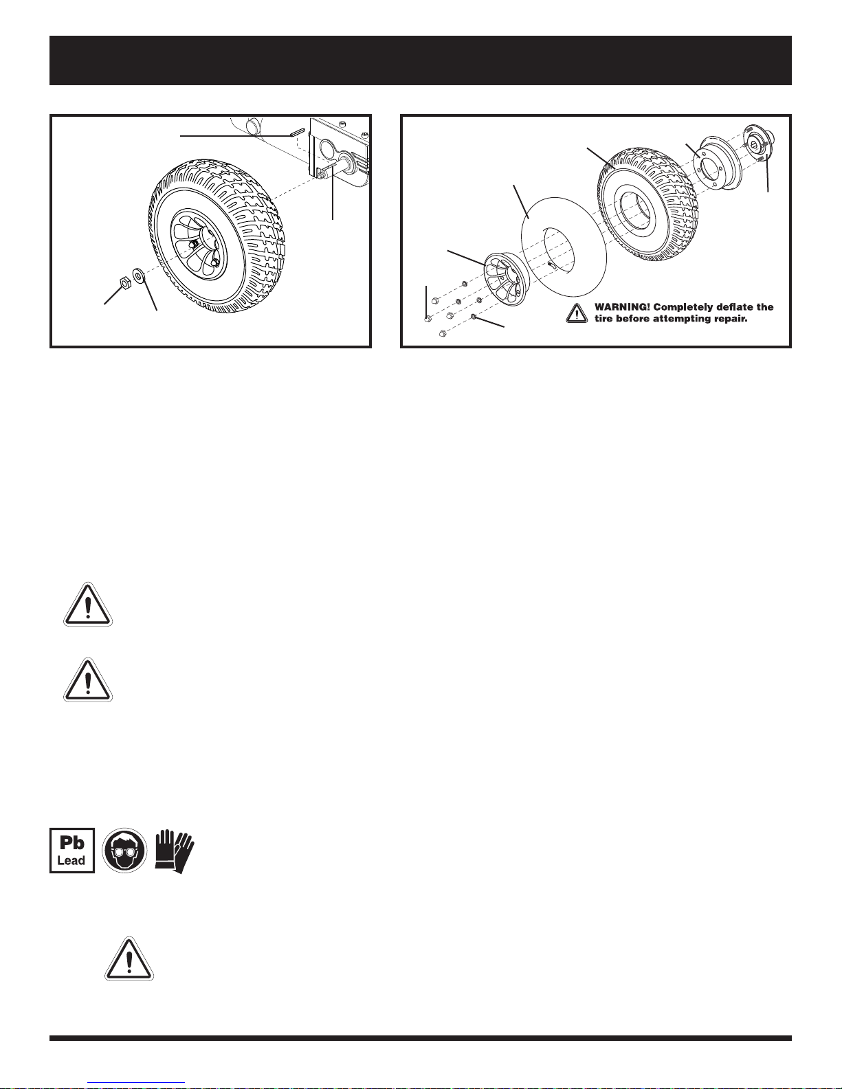
AXEL KEY
TUBE
AXLE
SLOT
DRIVE
WHEEL
NUT
Figure 20. Quantum 610 Drive Wheel Figure 21. Quantum 610 Drive Wheel Disassmebled
DRIVE WHEEL
WASHER
FRONT RIM
HALF
NUTS
WASHERS
TYRE
REAR RIM
HALF
WHEEL
HUB
Follow these easy steps for a quick and safe repair for both pneumatic and solid tyres:
1. Turn off the power to the controller.
2. Set the power chair up on blocks.
3. If you are changing a pneumatic tyre, completely defl ate it before removing the wheel.
4. Remove the drive wheel nut and washer from the axle. See fi gure 20.
5. Pull the wheel off the axle.
6. Remove the nuts and washers from the wheel hub and separate the rim halves. See fi gure 21.
7. Remove the old tube from the pneumatic tyre and replace it with a new tube or replace the entire assembly if
it is a solid tyre.
8. Reassemble the rim halves and reinstall the nuts and washers to the wheel hub.
9. Slide the wheel back onto the axle. Make sure that the key is in the axle slot.
WARNING! Ensure that the axle key is properly installed into the axle slot when mounting the
wheel. If not installed securely, the braking system is disengaged wihch may cause personal
injury and/or product damage may result.
10. Reinstall the drive wheel nut and washer to the axle and tighten.
WARNING! Make sure both the nut and washer are reinstalled and secured properly.
11. Infl ate pneumatic tyres to the psi/bar/kPa air pressure rating indicated on each tyre.
12. Remove the power chair from the blocks.
Battery Replacement
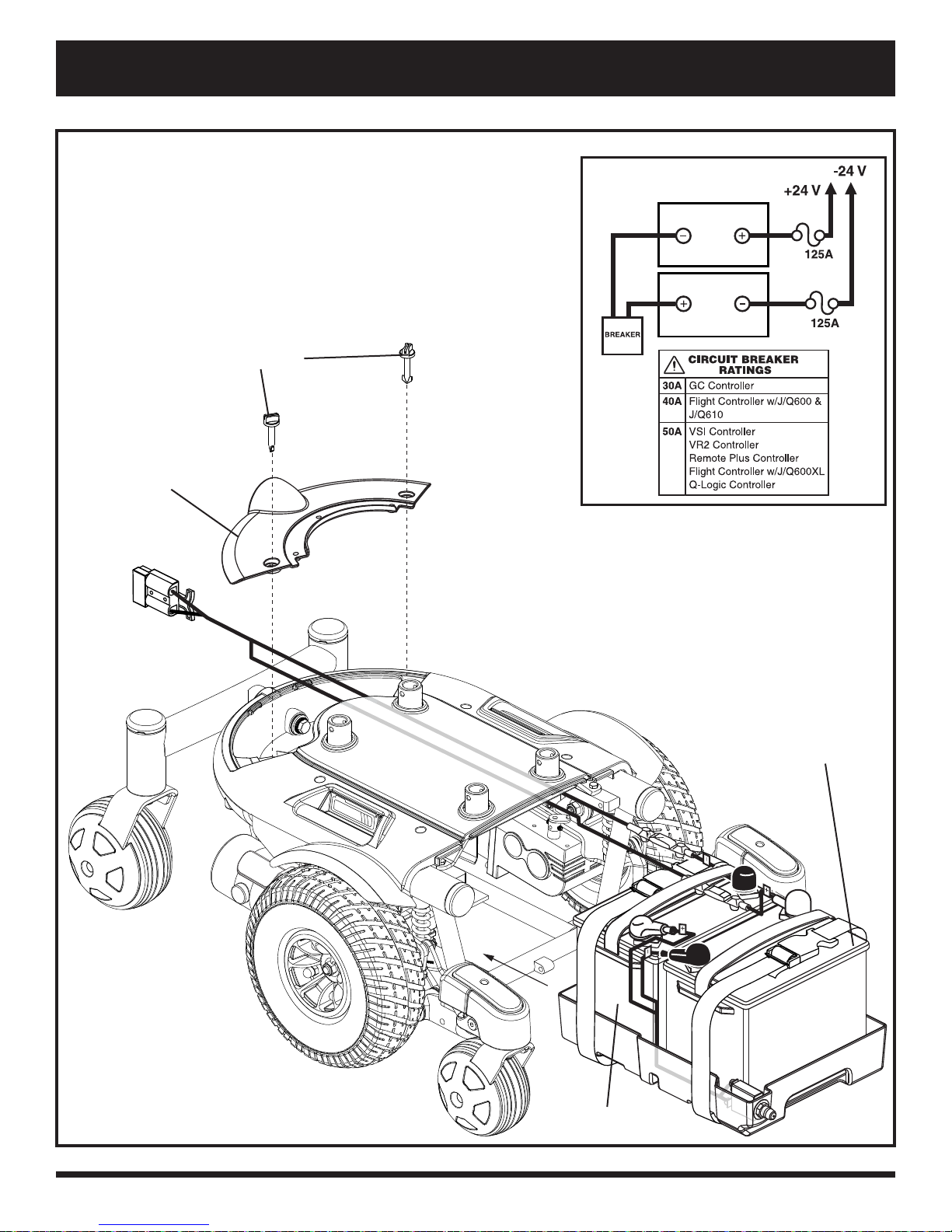
A battery wiring diagram is printed on a decal located on the front battery tray. See VI. “Batteries and Charging”
for correct battery specifi cations.
MANDA T ORY! Ba ttery posts, terminals and related accessories contain lead and lead
compounds. Wear goggles and gloves when handling batteries and wash hands after
handling.
WARNING! The batteries in your power chair should only be serviced or replaced by
a Quantum Rehab Dealer or a qualifi ed technician.
WARNING! Do not replace batteries when seat is occupied.
WARNING! Power chair ba tteries are heavy . See specifi cations table. If you are unable
to lift that much weight, be sure to get help. Use proper lifting techniques and avoid
lifting beyond your capacity.
WARNING! Do not mix old and new batteries. Always replace both batteries at the
same time.
Quantum 610 www.pridemobility.com 27
Page 28

VII. CARE AND MAINTENANCE
PROHIBITED! Keep tools and other metal objects away from the battery terminals. Contact with
tools can cause electrical shock.
You may need the following to change your batteries:
metric/standard socket set and ratchet
adjustable spanner
To replace the batteries:
1. Turn off the power to the controller.
2. Make sure that the power chair is in drive mode. See III. “Your Power Chair.”.
3. Loosen the rear shroud fasteners.
4. Remove the rear shroud. See fi gure 22.
5. Disconnect the battery harness from the rear battery.
6. Remove the retaining pin and lift off the front cover using the foot platform bracket. See fi gure 16.
7. Slide the battery tray forward.
8. Disconnect the battery harness from the front battery.
9. Unfasten the hook and loop straps from both batteries.
10. Remove the batteries.
11. Install new batteries.
12. Fasten the hook and loop straps around both batteries.
13. Connect the battery harness to the front battery according to the battery wiring diagram. See fi gure 22.
WARNING! Make sure you tighten the fasteners so that the connections are secure.
14. Slide the battery tray back into the power base.
15. Connect the battery harness to the rear battery.
16. Reinstall the front cover.
17. Reinstall the rear shroud and tighten the fasteners.
18. Charge the batteries. See VI. “Batteries and Charging.”
When to See Your Quantum Rehab Dealer for Service
The following symptoms could indicate a serious problem with your power chair. If necessary, contact your
Quantum Rehab Dealer. When calling, have the model number, serial number, nature of the problem, and the error
code if available.
Motor noise
Frayed harnesses
Cracked or broken connectors
Uneven wear on any of the tyres
Jerky motion
Pulling to one side
Bent or broken wheel assemblies
Does not power up
Powers up, but does not move
Loose seat or seating components
Corrective Maintenance
If the battery condition meter does not light up when you turn on the power:
Check the harness connections. Make sure they are tight.
Check the circuit breaker. Reset it if necessary.
Check the battery connections.
If the above conditions prove normal, you can load test the batteries with a battery load tester. These testers are
available at automotive parts stores. Disconnect both batteries before load testing and follow the directions that
come with the load tester. If either one of the batteries fails the load test, replace both of them. If your power chair
still does not power up, contact your Quantum Rehab Dealer.
28 www.pridemobility.com Quantum 610
Page 29
VII. CARE AND MAINTENANCE
Battery Set Confi guration:
+ = Positive (Red) Terminal Post
- = Negative (Black) Terminal Post
Connect Red wires to Red Positive (+) Terminal Posts.
Connect Black wires to Black Negative (–) T erminal Posts.
REAR SHROUD FASTENERS
REAR SHROUD
BATTERY WIRING DIAGRAM LABEL
FRONT BATTERY
REAR BATTERY
Figure 22. Battery Installation
Quantum 610 www.pridemobility.com 29
Page 30

Page 31
Quantum 610
Serial #
 Loading...