

Page 1
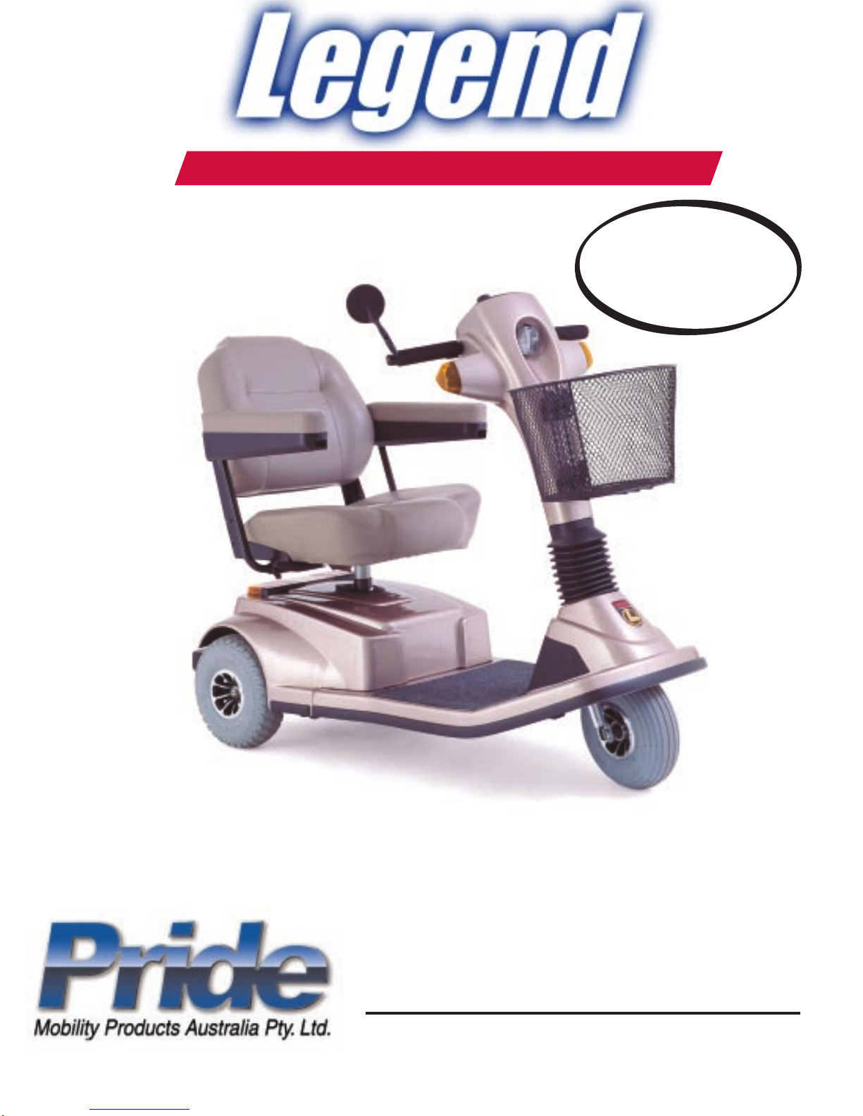
Owner ’s Manual
ATTENTION:
Read everything
in this manual
before operating
your Legend
The Ultimate In Style & Performance
®
21 Healey Road
Dandenong, 3175
Victoria, Australia
www.pridemobility.com
Page 2

SAFETY GUIDELINES
Please read and follow all instructions in this owners manual before attempting to operate your
Scooter for the first time. If there is anything in this manual you do not understand, or if you
require additional assistance for set-up, contact your local authorized Pride provider.
Using your Pride product safely depends upon your diligence in following the warnings, cautions, and instructions in this owners manual. Using your Pride product safely also depends
upon your own good judgement and/or common sense, as well as that of your provider, caregiver,
and/or healthcare professional. Pride is not responsible for injuries and/or damage resulting
from any persons failure to follow the warnings, cautions, and instructions in this owners manual.
Pride is not responsible for injuries and/or damage resulting from any persons failure to exercise good judgement and/or common sense.
The symbols below are used throughout this owners manual to identify warnings and cautions. It
is very important for you to read and understand them completely.
WARNING! Failure to heed the warnings in this owners manual may result in personal injury.
CAUTION! Failure to heed the cautions in this owners manual may result in damage to your
Scooter.
Copyright © 2002
Pride Mobility Products Australia Pty. Ltd.
INFMANU1334/REV D/OCTOBER 2002
2
Legend
Page 3

CONTENTS
I. INTRODUCTION......................................................................................................................... 4
II. SAFETY ......................................................................................................................................... 6
III. SPECIFICATIONS ..................................................................................................................... 9
IV. DESCRIPTION .......................................................................................................................... 11
V. BATTERIES AND CHARGING ............................................................................................ 17
VI. OPERATION ............................................................................................................................... 21
VII. COMFORT ADJUSTMENTS................................................................................................ 23
VIII. DISASSEMBLY AND ASSEMBLY ..................................................................................... 26
IX. TROUBLESHOOTING ............................................................................................................ 29
X. CARE AND MAINTENANCE ................................................................................................ 31
XI. WARRANTY ................................................................................................................................33
3Legend
Page 4

I. INTRODUCTION
Welcome to Pride Mobility Products Australia Pty. Ltd. (Pride). Congratulations on the purchase of your new
Legend. The Legend design combines the most advanced state-of-the-art components with modern, attractive
styling. We are certain that the design features and trouble-free operation of your new Legend will add convenience to your daily living.
At Pride, your safety is important to us. Please read and follow all instructions in this manual before at-
tempting to operate your Legend for the first time. These instructions were produced for your benefit. Your
understanding of these instructions is essential for the safe operation of your new Legend.
Pride is not liable for damage to property or personal injury arising out of unsafe use of a Legend. Pride is also not
liable for any property damage or personal injury arising out of the failure of any person and or/user to follow the
instructions and recommendations set forth in this manual or any other instructions or recommendations contained
in other Legend related literature issued by Pride or contained on the Legend itself.
This owners manual is compiled from the latest specifications and product information available at the time of
publication. We reserve the right to make changes as they become necessary. Any changes to our products may
cause slight variations between the illustrations and explanations in this manual and the product you have purchased.
If you experience any problems with your Legend that you are unable to resolve, or if you do not feel capable of
safely following any of the instructions and/or recommendations contained in this manual, please contact your
authorized Pride provider for assistance.
Once you understand how to operate and take care of your Legend, we are certain that it will give you years of
trouble-free service and enjoyment.
INFORMATION EXCHANGE
We want to hear your questions, comments, and suggestions regarding this owners manual. We would also like to
hear about the safety and reliability of your new Legend, and about the service you receive from your authorized
Pride provider.
Please notify us of any change of address, so we can keep you apprised of important information regarding safety,
new products, and new options that can increase your ability to use and enjoy your Legend. Please feel free to
write us at the address below:
Pride Mobility Products Australia Pty. Ltd.
21 Healey Road
Dandenong, 3175
Victoria, Australia
4
Legend
Page 5

I. INTRODUCTION
PRIDE OWNERS CLUB
As a Pride product owner, you are invited to register your products warranty and enroll in the Pride Owners Club.
You may do so by filling out and returning your enclosed registration card or by visiting Prides web site at
www.pridemobility.com. As a registered member, each time you visit our site, you will have access to the most
interactive and honest educational venue available today for people with mobility needs, their families, and friends.
From our home page, click on the button that reads Owners Club to enter a page dedicated to current and
potential Pride product owners. You will gain access to interviews, stories, recreation ideas, daily living tips,
product and funding information, and interactive message boards. Message boards invite you to communicate with
other Pride customers as well as Pride representatives who are available to assist you with any questions or
concerns you may have. You will receive a free gift simply for registering with the Pride Owners Club.
My Authorized Pride Provider Is:
Name:_______________________________________________________________________________
Address:_____________________________________________________________________________
Phone Number:________________________________________________________________________
Quick Reference Information:
Legend Model:__________________________________________________________________________
Serial Number:__________________________________________________________________________
Purchase Date:________________________________________________________________________
NOTE: If you ever lose or misplace your warranty card or owners manual,write to us and we will be glad
to send you a new one immediately.
5Legend
Page 6

II. SAFETY
You must read this entire manual and understand all of the safety precautions before attempting to operate your
new Scooter for the first time.
SAFETY PRECAUTIONS
n Do not operate your Scooter in icy or slippery conditions or on salted surfaces (i.e., walks or roads). Such use
may result in an accident, personal injury, or adversely affect the performance and/or safety of your Scooter.
n Do not operate or store your Scooter where it may be exposed to inclement weather conditions such as rain,
snow, mist and below-freezing temperatures (such as storage on an outside car/van lift). Attempting to operate
the Scooter in such conditions can damage the electronics and potentially result in loss of control.
n Do not operate your Scooter where you cannot safely and legally walk. Use extreme caution when driving on
busy streets, in parking lots, or in shopping malls. Always assume that you cannot be seen by motor vehicle
drivers.
n Lock your seat into place and remove the key from the key switch before you get on or off of your Scooter.
n Lock the seat into position before you operate your Scooter.
n Do not operate your Scooter with the seat in the reclined position (if so equipped).
n Make certain that the tyres are properly inflated to (30 psi).
n Do not operate your Scooter while you are under the influence of alcohol. Operating powered vehicles while
you are under the influence of alcohol impairs your ability to operate the Scooter in a safe manner and may
violate certain laws.
n Do not operate your Scooter without first consulting your physician regarding any concerns you have about
physical limitations that could prevent you from safely operating your Scooter.
n Do not operate your Scooter if you are taking medication which may impair your ability to operate the Scooter
in a safe manner.
n Do not drive your Scooter across the side of a hill or diagonally up or down a hill; do not stop, if possible, while
driving up or down an incline.
n Keep both hands on the tiller and your feet on the floorboard at all times while operating your Scooter. This
driving position gives you the most control over your vehicle.
n Proceed with extreme caution when driving near raised surfaces or unprotected ledges or drop-offs (kerbs,
porches, stairs, etc.).
n Drive slowly through turns.
n Do not use your Scooter as a seat in a moving vehicle. Your Scooter is not designed for such use and cannot
protect you in the event of an automobile accident or an abrupt stop.
n Always protect batteries from freezing temperatures and never charge a frozen battery. This damages the
battery and may cause personal injury. Attempting to charge a battery in freezing conditions does not prevent
a battery from freezing.
n Battery posts, terminals and related accessories contain lead and lead compounds. Wash hands after handling.
WARNING! Do not expose the electronics to any type of moisture at any time (rain, snow, mist or
wash). Such exposure can damage the electronics. Never attempt to ride a Scooter that has been
exposed to moisture until it has dried thoroughly.
CAUTION! Secure the batteries before loading your Scooter into another vehicle for transport.
CAUTION! Disconnect the batteries if you are not going to operate your Scooter for more than 48
hours.
6
Legend
Page 7
II. SAFETY
As you begin to use your Scooter during daily activities, you will encounter situations that may require some
practice. Simply take your time as you operate your Scooter and you will soon be in full and confident control as
you maneuver through doorways, on and off of elevators, up and down ramps, and over moderate terrain.
DOORS
n Determine if the door opens toward or away from you.
n Use your hand to turn the knob or push the handle or push-bar.
n Drive your Scooter slowly forward to push the door open, or drive your Scooter slowly backwards to pull the
door open.
ELEVATORS
Modern elevators have a door-edge safety mechanism that when pushed, reopens the elevator door(s).
n If you are in the doorway of an elevator when the door(s) begin to close, push on the rubber door edge or
allow the rubber door edge to contact the Scooter to reopen the door.
n Use care that pocketbooks, packages, or Scooter accessories do not become caught in the elevator doors.
RAMPS AND OTHER INCLINES
More and more buildings have ramps with specified degrees of inclination, designed for easy and safe Scooter
access. Some ramps may have turning switchbacks that require you to have good cornering skills on your Scooter.
n Take wide swings with your Scooters front wheel(s) around any tight corners. If you do that, the rear wheels
will follow a wide arc and will not cut the corner short, bump into, or get hung up on any railing corners.
n When driving down a ramp, keep your Scooters speed adjustment dial. See IV. Description. Set to the
tortoise (slowest speed setting) to ensure a safely controlled descent.
n Avoid sudden stops and starts.
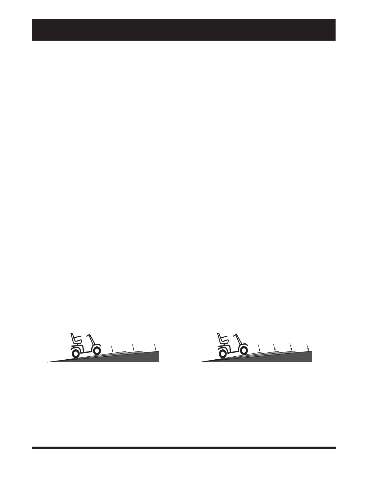
Other inclines may be natural or, if man-made, not designed specifically for Scooters. Figures 1 and 2 illustrate
your Scooters stability and its ability to climb grades under various weight loads and under controlled testing
conditions.
68 kg
12.3%
FIGURE 1. MAXIMUM RECOMMENDED INCLINE
ANGLE 3-WHEEL
90-113 kg
10.5%
136 kg
8.7%
FIGURE 2. MAXIMUM RECOMMENDED INCLINE
ANGLE 4-WHEEL
68 kg 90 kg 113 kg 136 kg
12.3%14.1%
10.5%
8.7%
7Legend
Page 8
II. SAFETY
Controlled incline testing was conducted with the Scooters seat in the highest position, adjusted backward on the
seat base to the farthest rearward position. These tests show that your Scooters ability to travel up inclines is
affected by your weight, your Scooters speed, your angle of approach to the incline, and your Scooter setup.
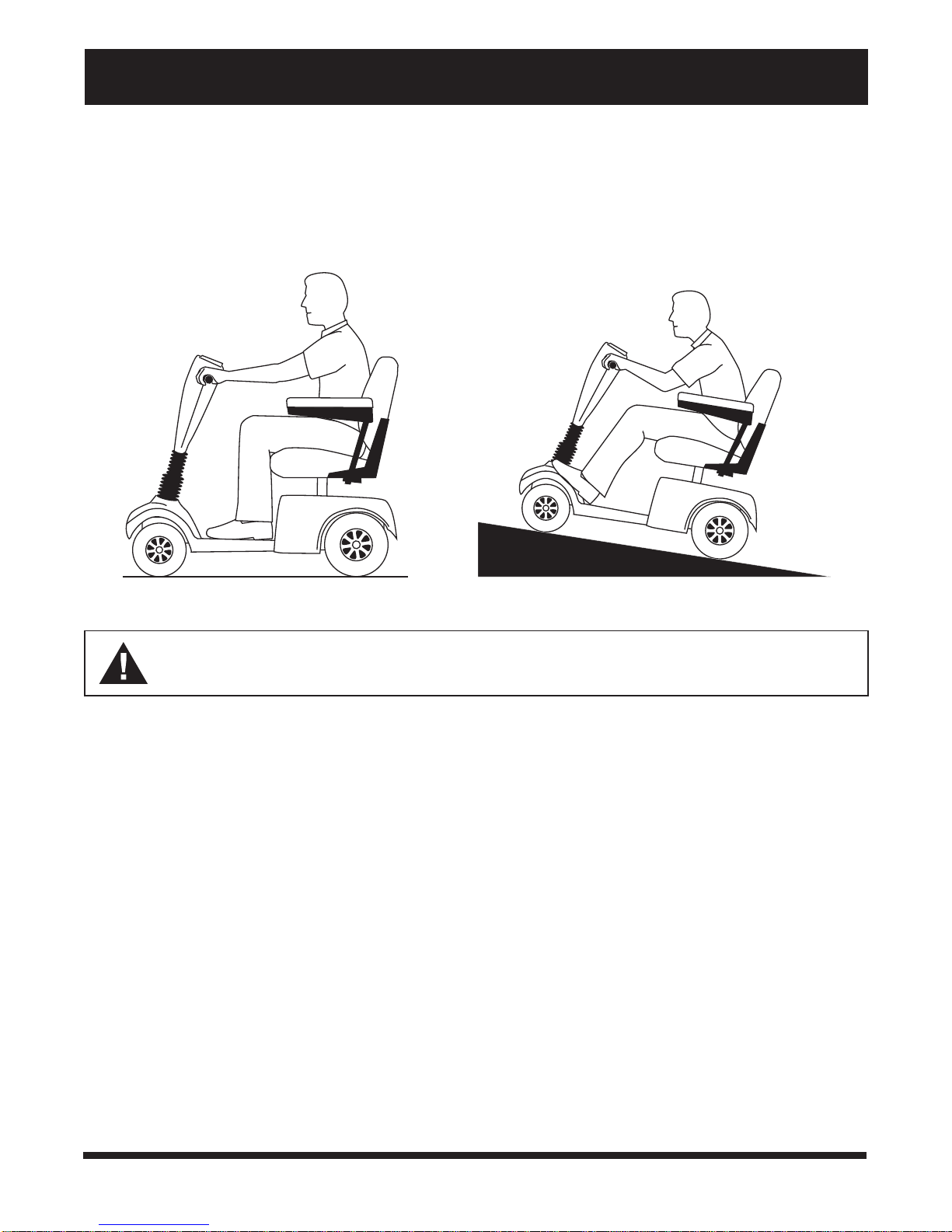
When you approach an incline, it is best to lean forward. See figures 3 and 4. This shifts the center of gravity of
you and your Scooter toward the front of the Scooter for improved stability.
FIGURE 3. NORMAL DRIVING POSITION
WARNING! Do not exceed the incline guidelines or any other specifications presented in
this manual.
FIGURE 4. INCREASED STABILITY DRIVING POSITION
DRIVING SURFACES
Your Scooter was designed to provide optimum stability under normal driving conditions dry, level surfaces
composed of concrete or asphalt. However, Pride recognizes that there will be times when you will operate your
Scooter on surfaces other than concrete or asphalt. For this reason, we also designed your Scooter to perform
admirably on packed soil, grass, and gravel.
n Use your Scooter safely on lawns and in park areas.
n Avoid tall grass that can become tangled in the running gear.
n Packed soil, gravel, driveways, or roads will not present a problem for your Scooter.
n Avoid loosely packed gravel and sand.
n If you feel unsure about a driving surface, avoid that surface.
8
Legend
Page 9
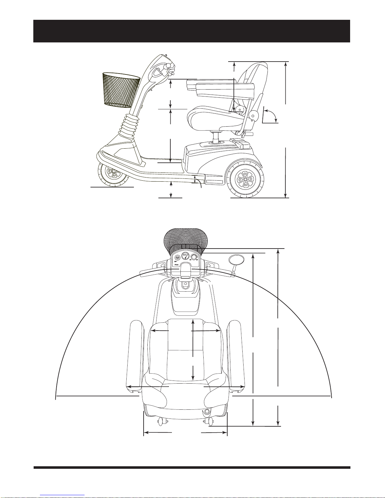
III. SPECIFICATIONS
47 cm
20 -31cm
99 -109 cm
FIGURE 5. LEGEND SPECIFICATIONS
42 - 52 cm
8 cm
Adjustable
90˚,100˚
102˚,105˚
3 cm
4 Wheel Length
3 Wheel Length
3 Wheel T urning Radius
46 cm
41 cm
61 - 71 cm
61 cm
128 cm
123 cm
114 cm 104 cm
4 Wheel T urning Radius
9Legend
Page 10

III. SPECIFICATIONS
Specifications
Length: 3-wheel: 123 cm; or 4-wheel: 128 cm
Width: 61 cm
Tyres: Type: Pneumatic
Front: 7,5 cm x 25 cm; Rear: 10 cm x 25 cm
Weight Capacity: 136 kg maximum
Battery Type (not included): Two 12-volt, 32 AH, U-1 type, sealed lead-acid (SLA); or
two 12-volt, 40 AH, U-1 type, SLA
Horsepower: 1,2 hp (peak)
Charger: Onboard 3-amp charger
Speed (Max): Variable up to 8,4 km/hr (60% reverse)
Maximum Grade: Please refer to figures 1 and 2.
Range: 12-volt 32 AH batteries: 32 - 40 km;
or 12-volt 40 AH batteries: 40 - 48 km
Turning Radius: 3-wheel: 104 cm; or 4 wheel: 114 cm
Body Colour: Candy Apple Red
Seating: Style: Contour medium back with sliders
Dimensions: 47 cm width (usable) x 47 cm height (usable) x
41 cm depth
Seat Cover Material: Gray vinyl with coloured piping
Armrests: Black
User adjustable seat height from ground: 52 cm to 62 cm
User adjustable seat height from Scooter deck: 42 cm to 52 cm
Included Features: Dynamic front and rear suspension; non-marring bumpers; full directional light
package; adjustable seat height and positioning; height adjustable armrests;
sliding seat; energy saving auto shutoff feature
Brakes: Dynamic regenerative braking and electromechanical disc park brake
Rear Wheel Drive: Sealed transaxle, 24 VDC motor
Wheels: MicroMag aluminum alloy wheels; black
Tiller Type: Infinitely adjustable
Freewheel Mechanism: Manual freewheel release lever located on upper-right rear portion of rear shroud
Legend Weight: Total weight with batteries: 12-volt 32 AH: 3-wheel: 48 kg; 4-wheel: 51 kg ; or 12-volt
40 AH: 3-wheel: 94 kg; 4-wheel: 102 kg
Component Breakdown:
Front Section: 3-wheel: 65 kg; 4 wheel: 73 kg
Rear Section (w/out batteries, shroud, or tray): 3-and-4 wheel: 18 kg
Rear Plastic Shroud: 2 kg
Seat: 17 kg
Batteries: 12-volt 32 AH: 11 kg each; or 12-volt 40 AH: 15 kg each
Tray: 2 kg
Basket: 1 kg
Front-to-rear Lockup: Lock pin and lever system
Ground Clearance: 8 cm
Optional Accessories: Cane/crutch holder, cup holder, front basket, front bumper, headlight, oxygen
holder, power seat assembly, rear basket, rear bumper, rearview mirror, safety flag,
taillight, walker holder, seatbelt
10
Legend
Page 11
IV. DESCRIPTION
Your Scooter is a motorized electric vehicle designed to enhance your personal mobility. It is an indoor/outdoor
Scooter that was designed to travel primarily on smooth surfaces such as pavement, roads, parking lots, floors, and
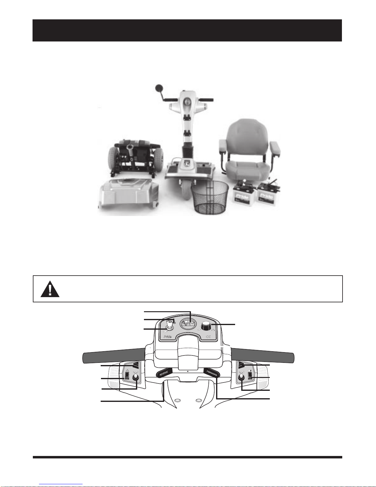
driveways. For easy transportation or storage, you can disassemble your Scooter into seven components. See
figure 6.
REAR SECTION
FRONT SECTION
SEAT
REAR SHROUD
FRONT BASKET
BATTERIES
FIGURE 6. LEGEND COMPONENTS
CONTROL CONSOLE MODULE
The control console module located on the front section houses all nthe controls you need to operate your Scooter.
See figure 7.
WARNING! Do not expose the control console module to moisture. In the event it does become
exposed to moisture, do not attempt to operate your Scooter until it has dried thoroughly.
BATTERY CONDITION METER
STATUS LED
KEY SWITCH
LEFT TURN INDICATOR
BUTTON
HAZARD LIGHT SWITCH
HORN BUTTON
THROTTLE CONTROL
LEVER (REVERSE)
SPEED ADJUSTMENT DIAL
RIGHT TURN INDICATOR
BUTTON
LIGHT SWITCH
HORN BUTTON
THROTTLE CONTROL
LEVER (FORWARD)
FIGURE 7. CONTROL CONSOLE MODULE
11Legend
Page 12

IV. DESCRIPTION
Speed Adjustment Dial
This dial allows you to preselect and limit your Scooters top speed.
n Set the speed between the slowest (image of the tortoise) and the fastest (image of the hare) speed settings.
Left and Right Turn Indicator Buttons
These buttons enable you to turn on the left and right turn indicator lights.
n Push the appropriate turn indicator button once to illuminate the signal light before turning your Scooter.
Your Scooters turn indicators are timed to shut off automatically.
Light Switch
This switch enables you to control your Scooters headlight and running (rear red) lights.
n Press this switch once to turn on the lights.
n Press it again to turn off the lights.
Horn Buttons
These buttons activate the warning horn.
n Ensure that the key is fully inserted and turned clockwise; then push either horn button to sound the horn.
Reverse and Forward Throttle Control Levers
These levers allow you to control the forward and the reverse speed up to the maximum speed you preset on the
speed adjustment dial. For instructions on how to operate your Scooters throttle control levers, see VI. Operation.
Hazard Light Switch
This switch enables you to control your Scooters amber hazard lights (4-way flashers).
n Toggle this switch to turn the hazard lights on and off.
Key Switch
This switch enables you to power up and power down your Scooter.
n Fully insert the key into the key switch and turn the key clockwise to power up your Scooter.
n Turn the key counterclockwise and pull the key out to power down your Scooter.
WARNING! If the key is removed from the key switch while your Scooter is in motion, the electronic brakes will engage and your Scooter will come to an abrupt stop.
Status LED
The Status LED alerts you to electrical problems that may occur with the Legend. The LED remains constantly lit while
your Scooter is on. If the Legend develops an electrical problem, the status LED will flash a code. See IX. Troubleshooting for flash codes.
Battery Condition Meter
When your Scooters key is fully inserted and turned clockwise to power up your Scooter, this meter indicates
approximate battery voltage strength. For further information on battery charging, see V. Batteries and Charging.
12
Legend
Page 13
IV. DESCRIPTION
REAR SECTION
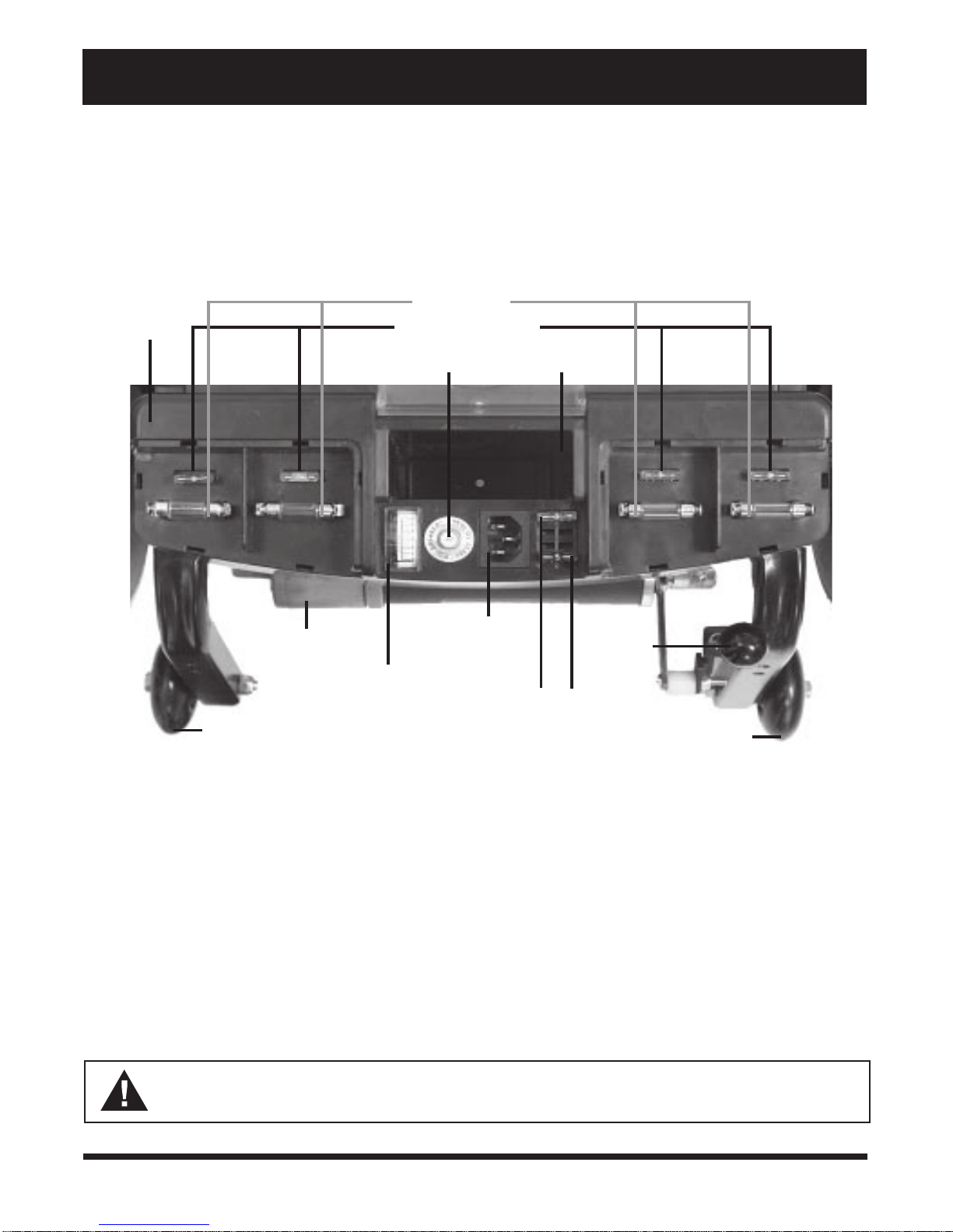
The rear section contains the electronics module, bulbs and fuses for the rear lights, fuses for the front console and
battery charger, the main circuit breaker (and reset button), the manual freewheel lever, the charger power cord
receptacle, the motor transaxle assembly, and the ammeter. See figure 8. The onboard battery charger and the
batteries are also contained in the rear of your Scooter, but are not visible in figure 8. The anti-tip wheels are at the
rearmost part of your Scooter.
ELECTRONICS
MODULE
MOTOR/TRANSAXLE
ASSEMBLY
ANTI-TIP WHEELS
24V 5W BULBS
3 V REAR LIGHT FUSES
MAIN CIRCUIT BREAKER
(RESET BUTTON)
CHARGER
POWER
CORD
AMMETER
RECEPTACLE
REAR STORAGE
COMPARTMENT
MANUAL
FREEWHEEL
LEVER
3-AMP CONTROL
CONSOLE MODULE FUSE
AND 5-AMP BATTERY
CHARGER FUSE
ANTI-TIP WHEELS
FIGURE 8. REAR SECTION (LIGHT COVERS REMOVED)
Bulbs
These 24V 5W bulbs are located beneath the rear shroud, directly under the running light and turn indicator/
hazard light covers. They provide illumination for your running lights, turn indicators, and hazard lights. For information on replacing these bulbs, see X. Care and Maintenance.
Fuses
The fuses protect your Scooters lighting and charging systems from receiving too much electrical current. The
fuses used in the Scooter are the same fuses that are used in automobiles. For information on replacing the fuses,
see X. Care and Maintenance.
n You need one 3-amp fuse for each of the 4 rear lights and one 3-amp fuse for the control console module.
n You need one 5-amp fuse for the battery charger.
WARNING! The replacement fuses must match the rating of the original fuses exactly. If you
install a fuse with an incorrect rating, you may damage the electrical system and create a potential
fire risk.
13Legend
Page 14

IV. DESCRIPTION
Main Circuit Breaker
When the voltage in your Scooters batteries becomes low or your Scooter is heavily strained because of excessive loads, the main circuit breaker may trip to protect your Scooters motor and electronics from damage. When
your Scooters main circuit breaker trips, the reset button pops out and your Scooter shuts down. If this occurs,
perform the following steps.
1. Allow a minute or so for your Scooters electronics to rest.
2. Push in the reset button to reset the circuit breaker.
Rear Storage Compartment
This compartment is for storing the charger power cord.
Manual Freewheel Lever
Whenever you want to push your Scooter for short distances, you can put it in manual freewheel mode.
WARNING! It is important to remember that when your Scooter is in manual freewheel mode, the
braking system is disengaged. Even though the motor is disengaged from the drive system when
your Scooter is put in manual freewheel mode, the motor can still run if the throttle lever is pushed.
Follow these safety rules when using the manual freewheel mode:
n Do not disengage the drive motors when your Scooter is on an incline; the Scooter could roll
down on its own and cause injury.
n Before placing your Scooter into or taking it out of manual freewheel mode, ensure the key is
removed from the key switch.
n Never sit on your Scooter when it is in manual freewheel mode.
n When you have finished pushing your Scooter, always return it to the drive mode to lock the
brakes.
n The manual freewheel lever is located on the end of the motor/transaxle assembly at the right rear of the
Scooter. See figure 8.
n Pull up on the manual freewheel lever to disable the drive system and the brake system; you will then be
able to push your Scooter.
n Push down on the manual freewheel lever to reengage the drive and brake systems, and take your Scooter
out of manual freewheel mode.
Charger Power Cord Receptacle
This receptacle enables you to plug the charger power cord into the Scooter. For further details on using the
charger power cord, refer to V. Batteries and Charging.
Motor/Transaxle Assembly
The motor/transaxle assembly is an electromechanical unit that converts electricity from the batteries into controlled mechanical energy that drives the Scooters wheels.
Ammeter
When the battery charger is plugged into a wall outlet, the ammeter indicates the charging status of your Scooters
batteries.
n When your Scooters batteries are fully charged, the amperage reading is at or near zero (0) amps.
14
Legend
Page 15

IV. DESCRIPTION
Anti-tip Wheels
The anti-tip wheels are an integral and important safety feature on your Scooter which prevent it from tipping
backward on an incline. They are located at the rearmost part of your Scooter.
WARNING! Do not remove your Scooters anti-tip wheels or modify your Scooter in any way that is
not authorized by Pride. Serious injury and/or damage to your Scooter may result.
Onboard Battery Charger (not shown)
The onboard battery charger converts household current (AC) to direct current (DC) and charges your Scooters
batteries. See V. Batteries and Charging for instructions on using the onboard battery charger.
Electronics Module
The electronics module receives electrical signals from the console controls and sends power to the motor, the
brakes, and the lighting system.
CAUTION! Do not expose the electronics module to moisture. If it does become exposed to moisture, do not attempt to operate your Scooter until it has dried thoroughly.
Batteries
The batteries store electrical energy that powers your Scooter. For directions on charging your batteries, see V.
Batteries and Charging.
15Legend
Page 16
IV. DESCRIPTION
OPTIONAL ACCESSORIES
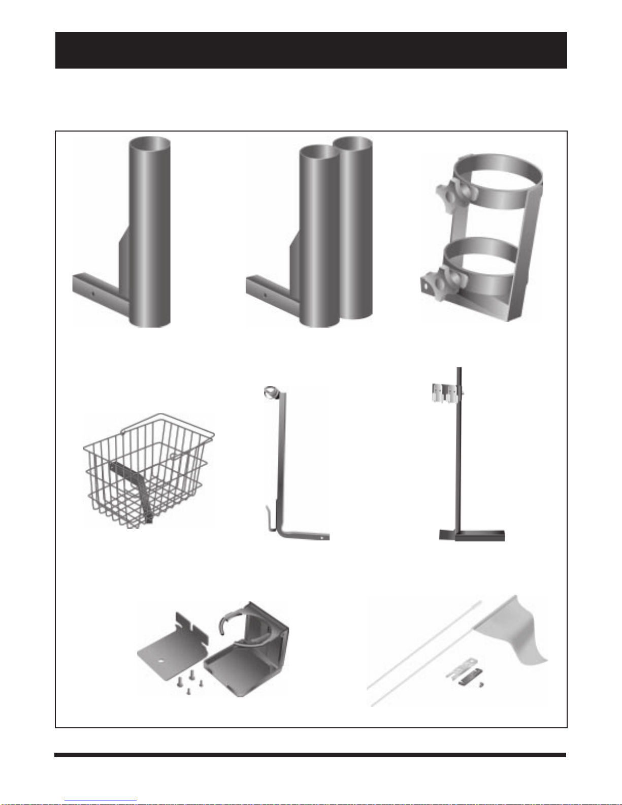
For information concerning the optional accessories in figure 9, see your authorized Pride provider.
SINGLE CANE/CRUTCH HOLDER
REAR BASKET
DOUBLE CANE/CRUTCH HOLDER
WALKER HOLDER
OXYGEN TANK HOLDER
FOREARM CRUTCH HOLDER
CUP HOLDER
FIGURE 9. OPTIONAL ACCESSORIES
16
SAFETY FLAG
Legend
Page 17
V. BATTERIES AND CHARGING
Your Scooter requires two long-lasting, 12V deep-cycle batteries that are sealed and maintenance free.
n Charge your Scooters batteries with the supplied onboard 3-amp battery charger prior to using it for the
first time.
n Keep your batteries fully charged to keep your Scooter running smoothly.
NOTE: Use only the onboard battery charger supplied with your Scooter.
READING YOUR BATTERY VOLTAGE
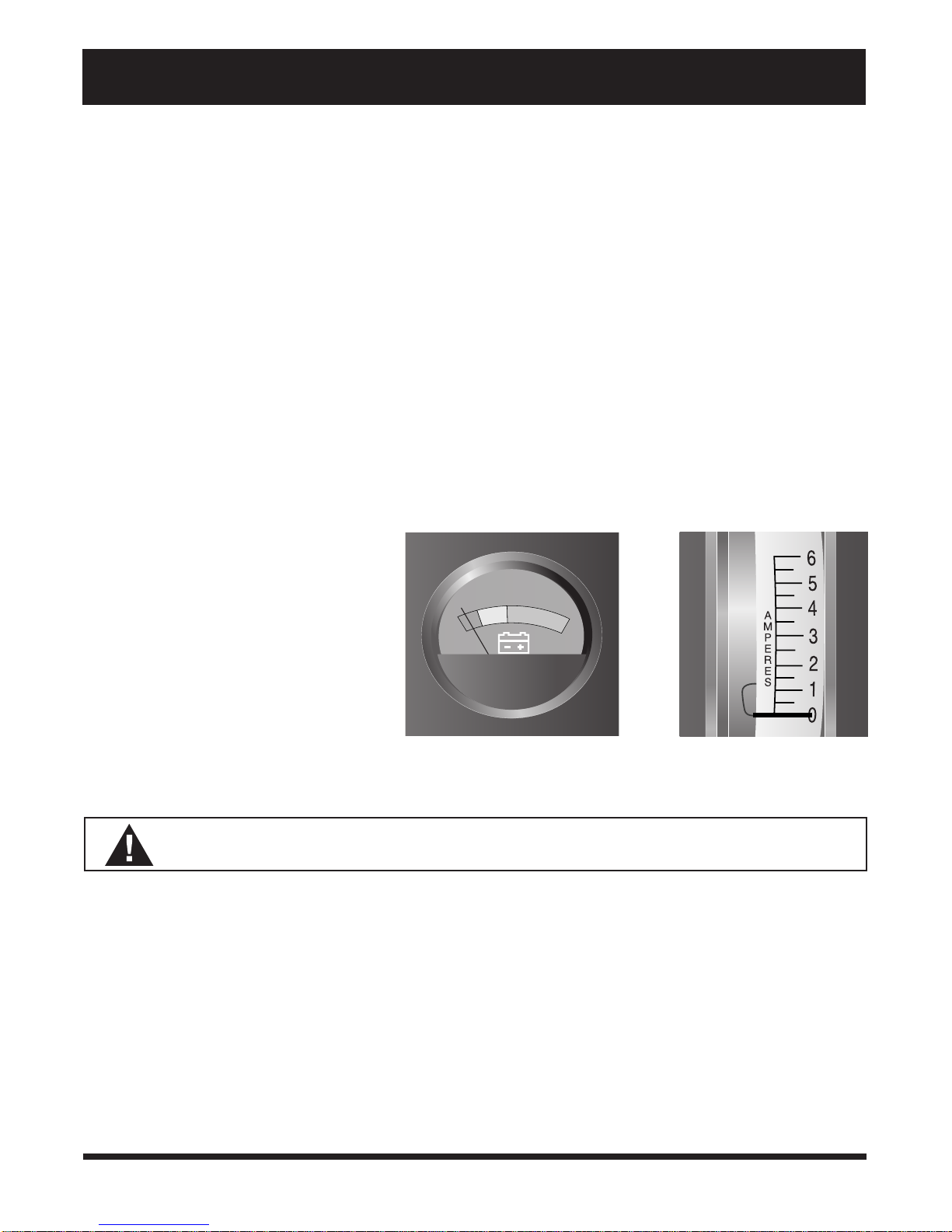
The battery condition LED on the control console assembly indicates the approximate strength of your batteries
using a color code. See figure 10. Green indicates fully charged batteries, yellow a draining charge, and red
indicates that an immediate recharge is necessary. To check the charge, you must first unplug the charger power
cord and power up your Scooter.
You can also check the charge using the ammeter located on the electronics module. The charger power cord
must be plugged into a standard wall outlet in order to obtain a reading. When the amperage reading is at or near
zero amps, charging is complete. See figure 11.
CHARGING YOUR BATTERIES
Follow these steps to safely charge your
batteries.
1. Position your Scooter close to a standard
wall outlet.
2. Remove the key from the key switch.
3. Ensure the manual freewheel lever is in the
drive (down) position.
FIGURE 10. BATTERY CONDITION METER
FIGURE 11. AMMETER
4. Plug the charger power cord into the charger power cord receptacle at the rear of your Scooter.
WARNING! Never use an extension lead to plug in your battery charger. Plug the charger directly
into a properly wired standard wall outlet.
NOTE: There is a charger inhibit function on your Scooter. The Scooter will not run and the battery
condition meter will not operate while the batteries are charging.
5. Extend the charger power cord and plug it into the wall outlet. We recommend charging your Scooters
batteries for 8 to 14 hours.
6. Periodically check the battery charge using the ammeter or the battery condition meter. (Remember that you
must insert the key in the key switch to check the charge on the battery condition meter.)
7. When the batteries are fully charged, unplug the charger power cord from the wall outlet and then from the
charger power cord receptacle at the rear of your Scooter.
8. Place the charger power cord in the rear storage compartment for safekeeping.
17Legend
Page 18
V. BATTERIES AND CHARGING
FREQUENTLY ASKED QUESTIONS (FAQS)
How does the charger work?
When your Scooters battery voltage is low the charger works harder sending more electrical current to the
batteries to bring up their charge. As battery voltage approaches full charge, the charger sends less electrical
current to the batteries. When the batteries are fully charged, the current sent from the charger is at nearly zero
amperage. Therefore, when the charger is plugged in, it maintains the charge on your Scooters batteries but does
not overcharge them. We do not recommend that you charge your Scooters batteries for more than 24 consecutive hours.
What if the Scooters batteries wont charge?
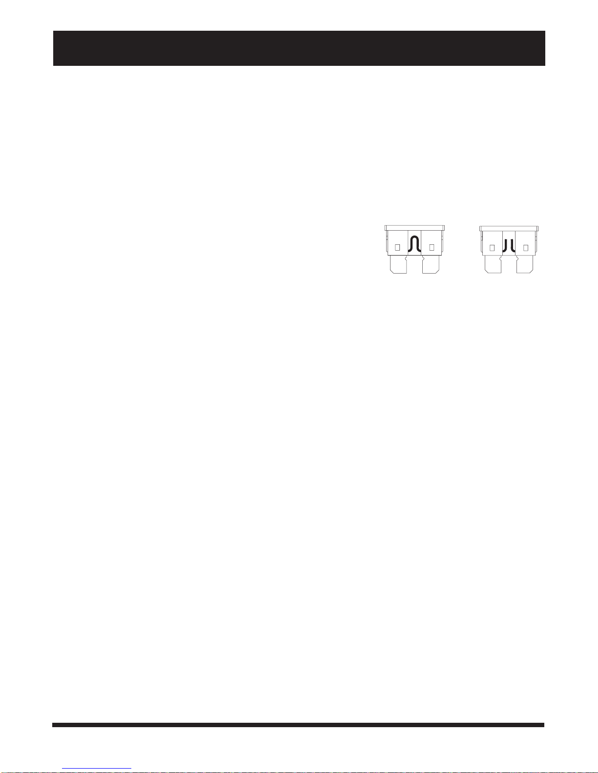
WORKING FUSE
BLOWN FUSE
There are a few checks you can perform if your batteries wont charge.
n Ensure that the battery cables are connected properly.
n Ensure that both ends of the charger power cord are inserted fully.
n Ensure that the 5-amp charger fuse has not blown. See figure 12.
FIGURE 12. FUSE CONDITIONS
Can I use a different charger?
For the safest, most efficient, and balanced charging of your Scooters batteries, you should simultaneously charge
both batteries using only the supplied onboard battery charger.
How often must I charge the batteries?
Two major factors must be considered when deciding how often to charge your Scooters batteries: All day
Scooter use on a daily basis and infrequent Scooter use.
With these considerations in mind, you can determine just how often and for how long you should charge your
Scooters batteries. We designed the onboard charger so that it does not overcharge your Scooters batteries.
However, you may encounter some problems if you do not charge your batteries often enough and if you do not
charge them on a regular basis. Following the five guidelines below will provide safe and reliable battery operation
and charging.
n If you use your Scooter daily, charge its batteries as soon as you finish using it for the day. Your Scooter will
be ready each morning to give you a full day of service. We recommend you charge your Scooters batteries for 8 to 14 hours after daily use.
n If you use your Scooter once a week or less, charge its batteries at least once a week for 12 to 14 hours at
a time.
n Keep your Scooters batteries fully charged.
n Avoid deeply discharging your Scooters batteries.
n Do not charge your Scooters batteries for more than 24 consecutive hours.
18
Legend
Page 19

V. BATTERIES AND CHARGING
How can I get maximum range or distance per charge?
Rarely will you have ideal driving conditions smooth, flat, hard driving surfaces with no wind or curves. You will
often face hills, sidewalk cracks, uneven and loosely packed surfaces, curves, and wind. All of these driving
conditions affect the distance or running time per battery charge. The following are a few suggestions for obtaining
the maximum range per battery charge.
n Always fully charge your Scooters batteries prior to your daily use.
n Maintain 30 psi (pounds per square inch) in all of your Scooters tyres.
n Plan your route ahead to avoid as many hills, cracked, broken, or soft surfaces as possible.
n Limit your baggage weight to essential items.
n Try to maintain an even speed while your Scooter is in motion.
n Avoid stop-and-go driving.
What type and size battery should I use?
We recommend deep-cycle batteries that are sealed and maintenance free. Both sealed lead-acid (SLA) and gel
cell are deep-cycle batteries that are similar in performance. Do not use wet-cell batteries, which have removable
caps.
NOTE: Do not remove the caps from sealed batteries. Water cannot be added to sealed batteries. Cap
removal voids the battery warranty and may cause damage to the batteries and to your Scooter.
Use these specifications to reorder deep-cycle batteries.
Type: Deep-cycle (SLA or gell cell)
Size: U-1 (32 amp hours (AH) only)
Voltage: 12V each
Amperage: 32 AH or 40 AH
To change a battery in your Scooter:
1. Remove the seat and the rear shroud. See VIII. Disassembly and Assembly.
2. Disconnect the battery tie-down strap.
3. Disconnect the battery cables from the electronics module.
4. Disconnect the battery cables from the battery terminals.
5. Remove the old battery.
6. Place a new battery in the battery well.
7. Connect the red battery cable to the positive (+) battery terminal.
8. Connect the black battery cable to the negative (-) battery terminal.
9. Reconnect the battery cables to the electronics module.
10. Fasten the battery tie-down strap.
11. Refit the rear shroud and the seat.
WARNING! Battery posts, terminals and related accessories contain lead and lead compounds.
Wash hands after handling.
19Legend
Page 20

V. BATTERIES AND CHARGING
Why do my new batteries seem weak?
Deep-cycle batteries employ a different chemical technology than that used in car batteries, nickel-cadmium batteries (nicads), or in other common battery types. Deep-cycle batteries are specifically designed to provide power,
drain down their charge, and then accept a relatively quick recharge.
We work closely with our battery manufacturer to provide batteries that best suit your Scooters specific electrical
demands. Fresh batteries arrive daily at the manufacturer and are shipped fully charged to our providers. During
shipping, the batteries may encounter temperature extremes that can influence their initial performance. Heat diminishes battery charge. Cold slows the available power and extends the time needed to recharge the battery.
It may take a few days for the temperature of your Scooters batteries to stabilize and adjust to their new room or
ambient temperature. More importantly, it takes a few charging cycles (a partial drain followed by a full recharge)
to establish the critical chemical balance that is essential to a deep-cycle batterys peak performance and long life.
Please follow these steps to properly break-in your Scooters new batteries for maximum efficiency and service life.
1. Fully recharge any new battery prior to initial use. This initial charging cycle brings the battery up to about 88%
of peak performance level.
2. Operate your new Scooter in familiar and safe areas. Drive slowly at first, and do not travel too far from your
home or familiar surroundings until you have grown accustomed to your Scooters controls and have properly
broken-in the batteries.
3. Fully recharge the batteries. This recharge should bring the batteries up to about 90% of their peak performance level.
4. Operate your Scooter again.
5. Fully recharge the batteries again.
6. After four or five charging cycles, the batteries are able to receive a charge up to 100% of their peak performance level and are able to last for an extended period of time.
How can I ensure maximum battery life?
Fully charged deep-cycle batteries provide reliable performance and extended battery service life. Keep your
Scooters batteries fully charged whenever possible. Batteries that are deeply discharged, infrequently charged, or
stored without a full charge may be permanently damaged and cause unreliable performance and limited service
life.
How should I store my Scooter and its batteries?
If you plan on not using your Scooter for an extended period of time, it is best to:
n Fully charge its batteries prior to storage.
n Disconnect the battery harnesses from the electronics module.
n Store your Scooter in a warm, dry environment.
n Avoid storing your Scooter where it will be exposed to temperature extremes.
WARNING! If your Scooters batteries do become frozen, do not attempt to charge
them. Cold or frozen batteries should be allowed to warm up for several days prior to recharging.
20
Legend
Page 21

VI. OPERATION
PRE-RIDE ADJUSTMENTS AND CHECKS
Familiarize yourself with the following checklist before you get on your Scooter. Some of the checks must be
performed prior to getting on your Scooter.
n Have you fully charged the batteries? See V. Batteries and Charging.
n Is the manual freewheel lever in the drive (down) position? See IV. Description. Never leave the manual
freewheel lever pulled up unless you are manually pushing your Scooter.
n Is your proposed path clear of people, pets, and obstacles?
n Have you planned your route to avoid adverse terrain and as many inclines as possible?
n Are you positioned comfortably in the seat? See Getting On Your Scooter, below.
n Is the seat at the proper height? See VII. Comfort Adjustments.
n Is the seat locked securely in place? See VII. Comfort Adjustments.
n Is the tiller handle at a comfortable setting and locked securely in place? See VII. Comfort Adjustments.
n Is the key fully inserted into the key switch? See IV. Description.
n Is the speed adjustment dial set to a slow setting? See IV. Description.
n Are you grasping the handgrips with a thumb resting on each side of the throttle lever? See Operating Your
Scooter, below.
n Does your Scooters horn work properly?
GETTING ON YOUR SCOOTER
1. Make certain that the key is removed from the key switch.
2. Stand at the side of your Scooter.
3. Push down on the seat lock lever and rotate the seat until it faces you.
4. Make certain that the seat is locked securely in position.
5. Position yourself comfortably and securely in the seat.
6. Push down on the seat lock lever and rotate the seat until you face forward.
7. Make certain that the seat is locked securely in position.
8. Make certain that your feet are safely on the floorboard.
OPERATING YOUR SCOOTER
After planning your route:
1. Set the speed adjustment dial to your desired speed.
2. Insert the key into the key switch and turn the key clockwise.
3. With your hands on the handgrips, use your thumb to push the right throttle lever to disengage your Scooters
parking brake and move forward. The electric parking brake automatically disengages and the Scooter accelerates smoothly to the speed you set with the speed adjustment dial.
4. Pull on the left handgrip to steer your Scooter to the left.
5. Pull on the right handgrip to steer your Scooter to the right.
6. Move the tiller to the center position to drive straight ahead.
7. Release the throttle lever to decelerate and come to a complete stop. The electromechanical parking brake
automatically engages when your Scooter comes to a stop.
8. To move in reverse, use your thumb to push the left throttle lever to disengage your Scooters brakes and move
rearward.
21Legend
Page 22

VI. OPERATION
WARNING! Before moving in reverse, always ensure your path is free of pedestrians, kerbs, and
potential hazards.
GETTING OFF YOUR SCOOTER
1. Bring your Scooter to a complete stop.
2. Make certain that the key is removed from the key switch.
3. Push down on the seat lock lever and rotate the seat until you are facing toward the side of your Scooter.
4. Make certain that the seat is locked securely in position.
5. Carefully get out of the seat and stand to the side of your Scooter.
6. You can leave the seat facing to the side to facilitate boarding your Scooter the next time you are going to
operate it.
WARNING! Never attempt to get on or off your Legend without first removing the key from the key
switch. This prevents the Scooter from moving if contact with the throttle control lever is made.
22
Legend
Page 23
VII. COMFORT ADJUSTMENTS
WARNING! Remove the key before adjusting the tiller or the seat. Never attempt to adjust
the tiller or the seat while the scooter is in motion.
TILLER ANGLE ADJUSTMENT
You can adjust the tiller to any position between the forward stop and the Scooter deck. The tiller adjustment
lever locks the tiller in place.
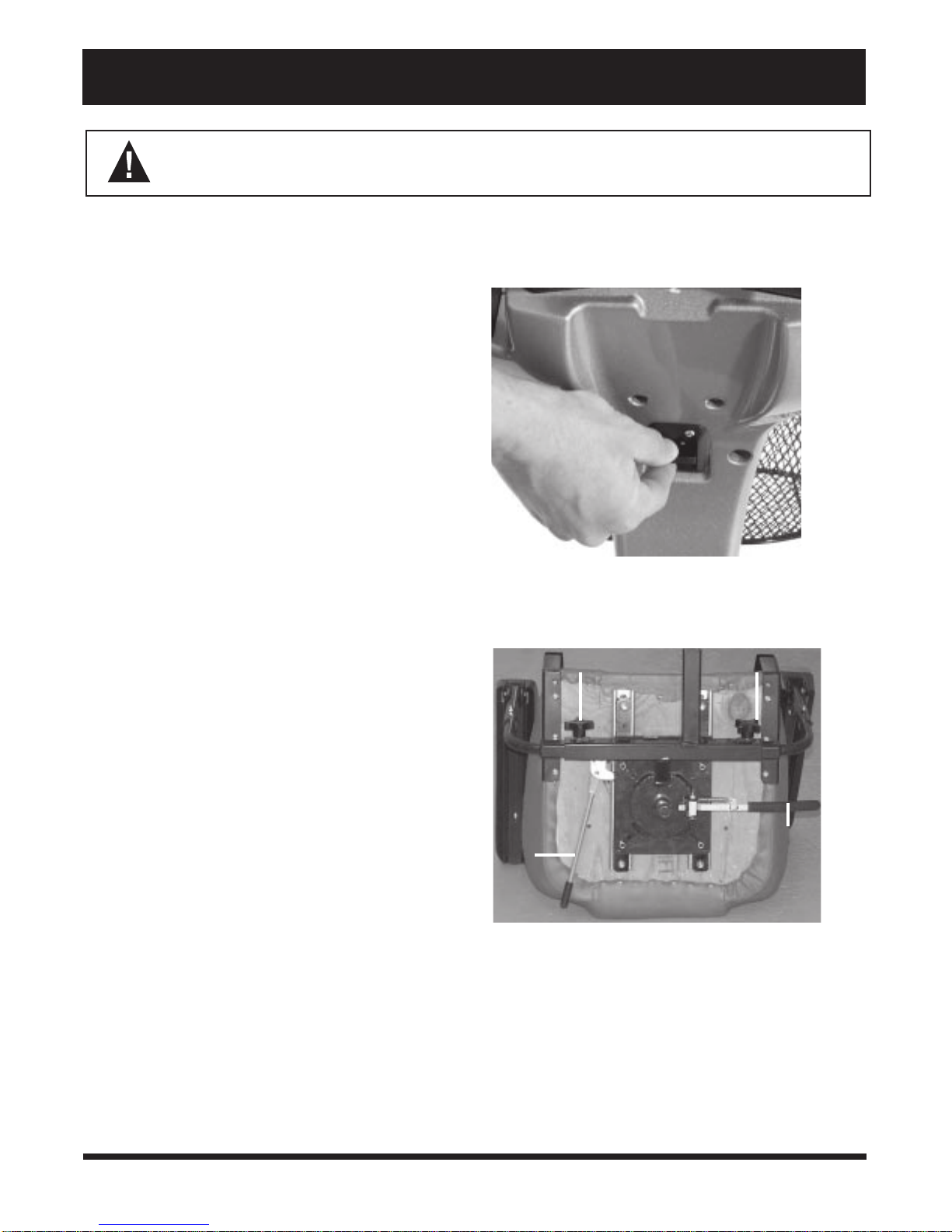
1. Pull up on the tiller adjustment lever. See figure 13.
2. Move the tiller to a comfortable position.
3. Release the tiller adjustment lever. The tiller will remain in the position you selected.
NOTE: In order to lower the tiller to the Scooter
deck, you must first remove the seat, rear shroud,
and both batteries. See VIII. Disassembly and Assembly.
FRONT-TO-BACK SEAT ADJUSTMENT
Your Scooter is equipped with a sliding seat that is operated like an automobile seat; you can reposition it forward or rearward.
1. Pull out the front-to-back seat release lever. See figure 14.
2. Move the seat forward or rearward.
3. Release the front-to-back seat release lever.
SEAT ROTATION
The seat lock lever locks the seat in one of four positions.
1. Push down on the seat lock lever to unlock the seat.
See figure 14.
2. Rotate the seat to the desired position.
3. Release the seat lock lever to lock the seat securely
in place. If the seat is not locked into position, gently
rock the seat back and forth until you hear the lever
click.
FIGURE 13. TILLER ADJUSTMENT LEVER
ARMREST ADJUSTMENT KNOBS
FRONT-TO-BACK
SEAT RELEASE
LEVER
FIGURE 14. SEAT ADJUSTMENTS
SEAT LOCK
LEVER
23Legend
Page 24

VII. COMFORT ADJUSTMENTS
ARMREST WIDTH ADJUSTMENT
The armrest width of your Scooter can be adjusted inward and outward.
1. Loosen the armrest adjustment knobs at the back of the seat frame. See figure 14.
2. Slide the armrests in or out to the desired width.
3. Tighten the armrest adjustment knobs.
The armrests also pivot upward to make getting on and off of your Scooter easier.
ARMREST HEIGHT ADJUSTMENT
You will need the following tools to adjust the height of the
armrests.
n 5/32 hex key
n 1/8 hex key
n 7/16 spanner
1. Loosen the setscrew on the side of the height adjustment tube with the 1/8” hex key . See figure 15.
2. Loosen and remove the acorn nut and screw holding
the height adjustment tube in place.
3. Raise or lower the height adjustment tube to the desired height.
4. Align the holes in the adjustment tube with the holes
in the armrest upright.
5. Insert the screw through the holes in both the height
adjustment tube and the armrest upright.
6. Install and tighten the acorn nut.
7. Tighten the setscrew on the side of the height adjustment tube.
8. Repeat for the other armrest.
SEAT HEIGHT ADJUSTMENT
ACORN
NUT
ARMREST
UPRIGHT
FIGURE 15. ARMREST HEIGHT ADJUSTMENT
HEIGHT ADJUSTMENT
TUBE
SETSCREW
24
Legend
Page 25
VII. COMFORT ADJUSTMENTS
You can position the Scooter seat to one of five different
heights.
1. Remove the seat and rear shroud from your Scooter.
See VIII. Disassembly and Assembly.
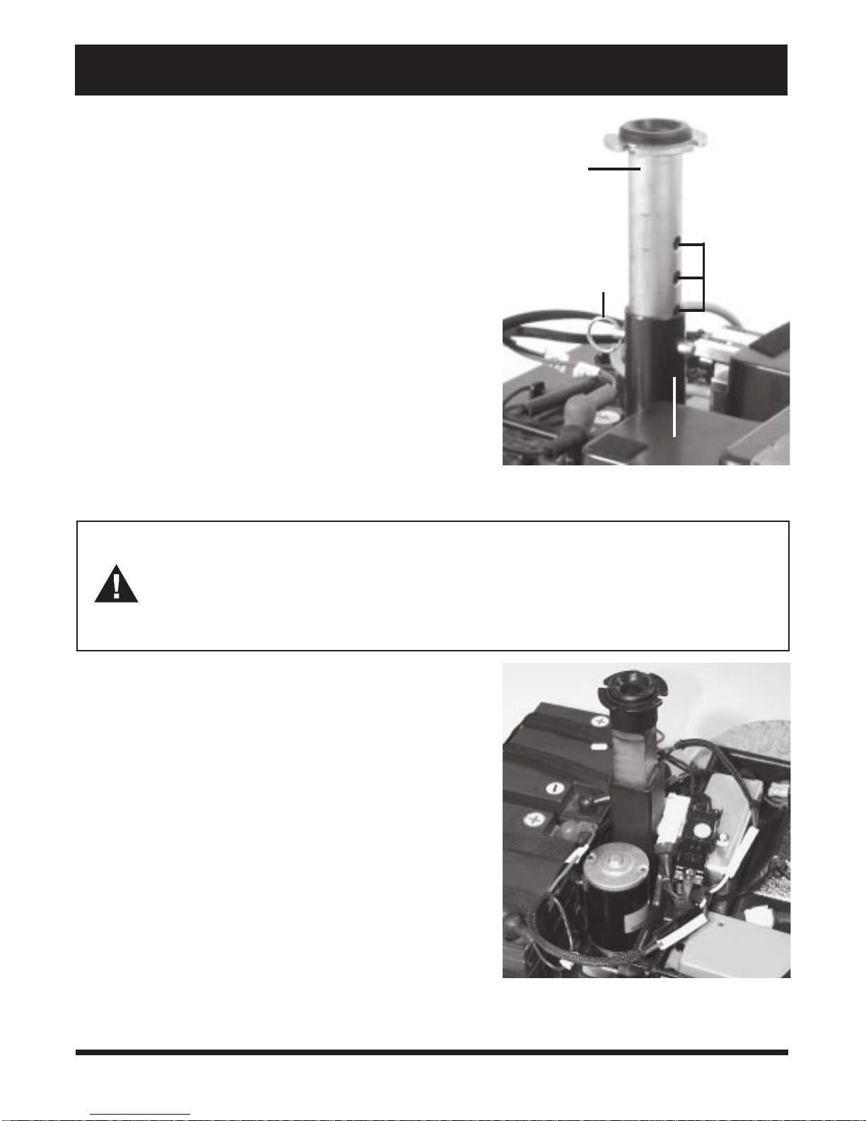
2. Use the attached ring to pull and remove the ball detent
pin from the seat post tower. See figure 16.
3. Raise or lower the seat post to the desired seat height.
4. Hold the seat post at that height and match up the adjustment holes in the seat post with the holes in the seat post
tower.
5. Fully insert the ball detent pin.
6. Replace the seat and the rear shroud.
POWER SEAT ACTUATOR (OPTIONAL)
SEAT POST
BALL DETENT PIN
ADJUSTMENT
HOLES
Your Scooter may be equipped with a power seat actuator. The actuator raises and lowers the seat automatically .
See figure 17.
WARNING! The power seat actuator is intended for operation only while the vehicle is stationary and on a level surface. Its pur pose is to aid you in reaching objects. Strict adherence to the following safety rules is vital to your safety:
n Do not attempt to raise or lower the seat while in motion.
n Do not operate your Scooter with the power seat elevated.
n Drive the vehicle only with the seat in the lowest position.
Operating Your Power Seat
1. Ensure your Scooter is level and stationary.
2. Toggle on the power seat switch.
3. To raise the power seat, place your hands on the handgrips
and use your thumb to push the right throttle control lever, located on the Scooters control console.
4. Release the lever when you have attained your desired
height.
5. To lower the power seat, place your hands on the
handgrips and use your thumb to push the left throttle
control lever, located on the Scooters control console.
6. Release the lever when you have attained your desired
height.
7. Ensure your seat is in the lowest position and toggle off
the power seat switch before you attempt to drive your
Scooter again.
The 3-wheel and 4-wheel Scooters are identical in disas-
SEAT POST TOWER
FIGURE 16. SEAT HEIGHT ADJUSTMENT
FIGURE 17. POWER SEAT ACTUATOR (OPTIONAL)
25Legend
Page 26
VIII. DISASSEMBLY AND ASSEMBLY
sembly and assembly. No tools are required. Always disassemble or assemble your Scooter on a level, dry surface
with sufficient room for you to work and move around your Scooter. Keep in mind that the disassembled sections
of the Scooter take up more floor space than the assembled Scooter.
DISASSEMBLY
You can disassemble the Scooter into seven pieces: the seat, the front frame, the front basket, the rear frame, the
rear shroud, and the two batteries. Place the Scooter in an area where you have sufficient clearance to move the
parts around. You need about 1.5 meters in all directions. You may need assistance to lift some of the Scooter
components. See III. Specifications for individual component weights.
1. Remove the key from the key switch.
2. Place the manual freewheel lever in the drive (down) position to make it easier for you to maneuver the rear
section.
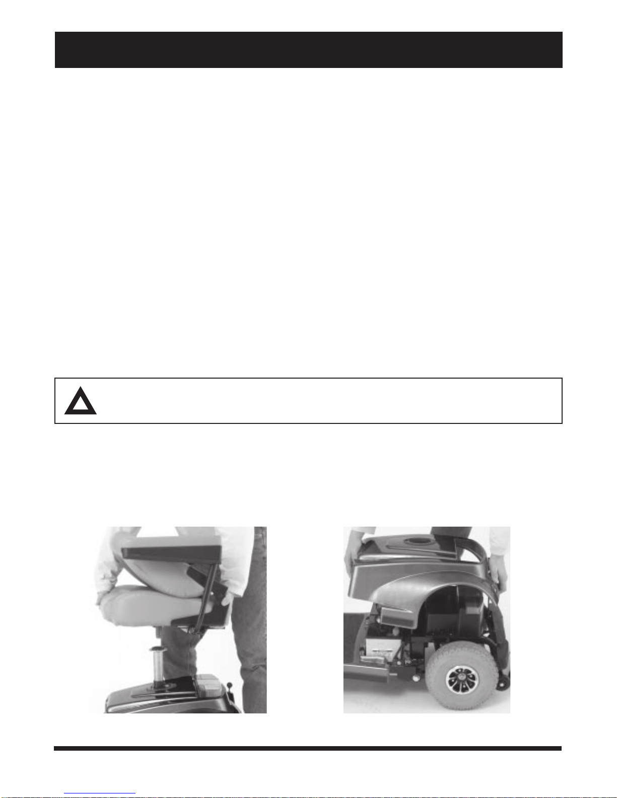
3. Ensure the seat is locked into position; then lift the seat up and off of your Scooter. See figure 18.
4. Gently lift the rear shroud off of your Scooter. See figure 19.
5. Disconnect the battery tie-down straps (if so equipped).
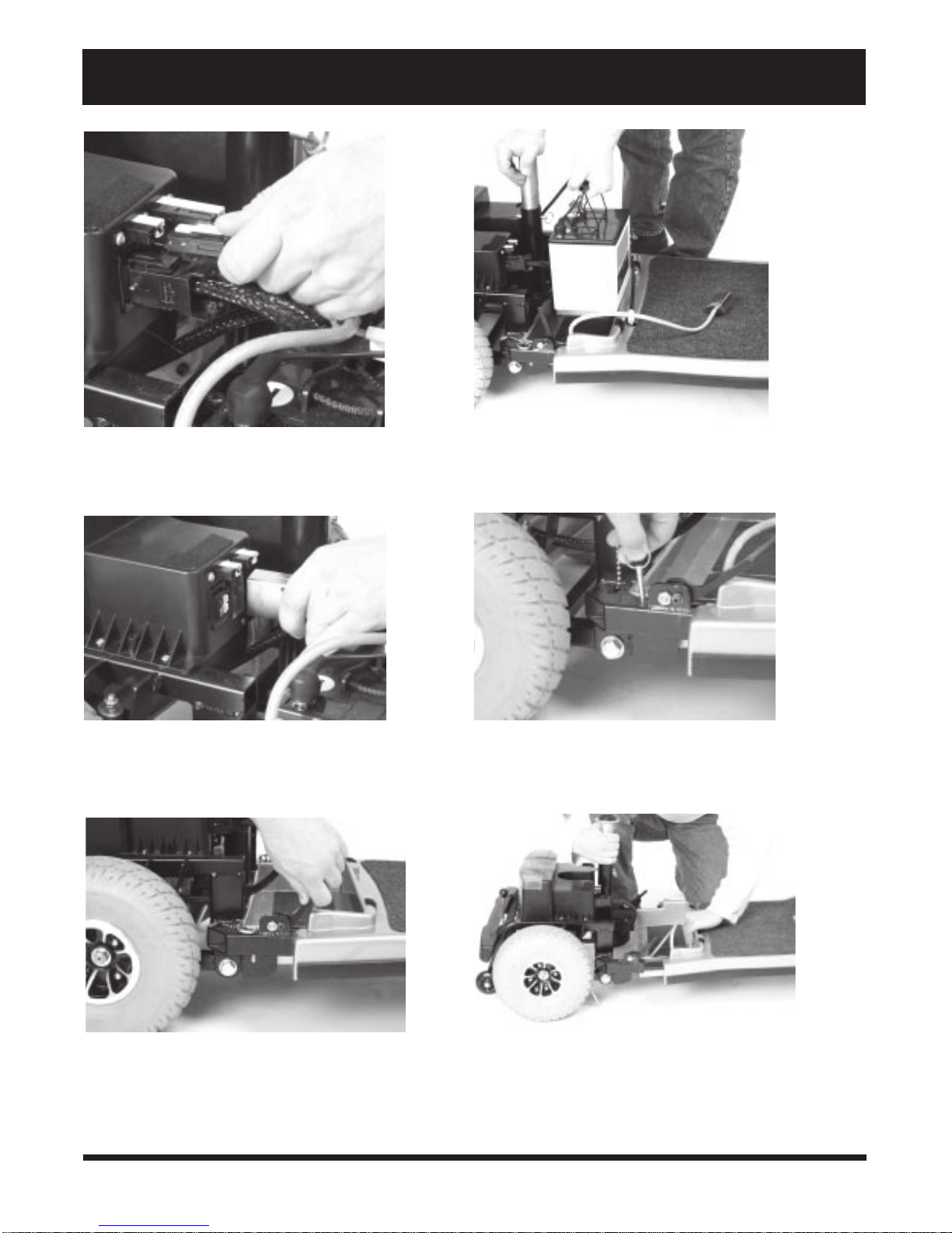
6. Unplug both battery harnesses; then lift both batteries from the battery wells. See figures 20 and 21.
7. Unplug the front-to-rear connector that attaches the front control console harness to the electronics module
harness. See figure 22.
CAUTION! Failing to unplug both battery harnesses and the front-to-rear connector prior to further
disassembly could result in permanent damage to your Scooter.
8. Grab the handle grip on the tiller, pull up on the tiller adjustment lever, and gently lower the tiller down to the
center of the Scooter chassis until it is fully lowered.
9. Remove the ball detent pin from the frame. See figure 23.
10. Move the camlock levers to the unlocked, vertical position. See figure 24.
11. Place one hand on the seat post tower, one hand on the front frame handle and gently slide the front and rear
sections apart. See figure 25.
FIGURE 18. REMOVING THE SEAT
26
FIGURE 19. REMOVING THE SHROUD
Legend
Page 27
VIII. DISASSEMBLY AND ASSEMBLY
FIGURE 20. UNPLUGGING THE BATTERY HARNESSES
FIGURE 22. UNPLUGGING THE FRONT-TO-REAR
CONNECTOR
FIGURE 21. LIFTING THE BATTERY
FIGURE 23. REMOVING THE BALL DETENT PIN
FIGURE 24. UNLOCKING THE CAMLOCK LEVERS
FIGURE 25. SEPARATING THE FRAME SECTIONS
27Legend
Page 28

VIII. DISASSEMBLY AND ASSEMBLY
ASSEMBLY
1. Pull up on the manual freewheel lever. See IV. Description. Placing your Scooter in freewheel mode may
make it easier for you to maneuver the rear section because the drive wheels are free to turn.
2. Position the front and rear sections of your Scooter as shown in figure 25.
3. Tilt the rear section to a horizontal position and insert the longer tube of the front end into the rear section first.
Make sure that the camlock levers are in the unlocked (vertical) position and the ball detent pins are removed.
4. Slide the two sections of the unit together until the front half reaches its insertion limit.
5. Secure the front and rear sections with the ball detent pins.
6. Push the camlock levers back to their locked (downward) position.
7. Plug the front-to-rear connector (located on the front section harness ) to the connector mating socket (found
on the rear electronics module).
8. Place the batteries in the battery wells, then reconnect the battery tie-down straps (if so equipped).
9. Connect the 2-pin battery harnesses into the mating harnesses that extend from the rear electronics module.
10. Gently place the rear shroud over the seat pedestal and slide it down into position. The Velcro fasteners hold
it in place.
11. Carefully lift the seat and slide the seat post (on the bottom of the seat frame) into the seat post tower.
12. Rotate the seat until it locks into place to complete assembly of your Scooter.
28
Legend
Page 29

IX. TROUBLESHOOTING
s
p
Any electromechanical device requires occasional troubleshooting. However, most problems that arise can usually
be solved with a bit of thought and common sense. Many of these problems occur because the batteries are not
fully charged or because the batteries are worn down and can no longer hold a charge.
DIAGNOSTIC FLASH CODES
Diagnostic flash codes help you perform basic troubleshooting quickly and easily. A diagnostic flash code will flash
from the status LED in the event one of the conditions listed below develops.
NOTE: Your Scooter will not run unless the flash code condition is resolved and the Scooter has been
powered down and then powered back up..
FLASH CODE CONDITION SOLUTION
n n n n n
n n
n n n n
n n n n n
n n n n n n
Batteries are too low to operate the
Scooter or the charger is operating.
Controller is hot; the Scooter seems to
be losing power.
Wigwag fault; your throttle control
levers are not responding.
The manual freewheel lever is in the
(up) freewheel position.
Scooter is operating with the charger
attached.
Charge batteries or unplug the charger power
cord from th e electrical outlet.
Shut down your Scooter for a minimum of
everal minutes to allow the controller to
cool.
Call your authorized Pride provider for
assistance.
Turn the Scooter key to the off position, then
ush the freewheel lever to the (do wn) drive
position, restart your Scoot er.
Unplug the charger cord from the charger
power cord receptacle.
What if all the systems on my Legend seem to be dead?
n Make certain that the key is in the on position.
n Check that the batteries are fully charged. See V. Batteries and Charging.
n Push in the the main circuit breaker reset button. See IV. Description.
n Make certain that both battery harnesses are firmly connected to the rear electronics module and to the
battery terminals. See VIII. Disassembly and Assembly.
n Make sure that the silver front-to-rear harness is firmly connected to the rear electronics module. See VIII.
Disassembly and Assembly.
n Be sure the auto shutoff feature hasnt been activated. See V. Batteries and Charging.
n Check the fuses. See X. Care and Maintenance for fuse replacement.
What if the motor runs but my Legend does not move?
n With the key turned to the on position, check the status LED. If the LED flashes three times, a short pause,
then two times, this is the manual freewheel lever code and means your Legend is in manual freewheel mode.
n When the manual freewheel lever is pulled up, the brakes are disengaged and all power to the transaxle is
cut.
n Push down the manual freewheel lever to restore normal operation to your Legend. See IV. Description.
29Legend
Page 30

IX. TROUBLESHOOTING
What if the main circuit breaker trips repeatedly? See IV. Description.
n Charge the Legends batteries more frequently. See V. Batteries and Charging.
n If the problem continues, have both your Legends batteries load tested by your authorized Pride provider.
n You may also perform the load test yourself. Battery load testers are available at most automotive parts stores.
n Follow the directions supplied with the load tester.
n See V. Batteries and Charging or III. Specifications for information about your Legends battery
type.
What if the battery condition meter dips way down and the motor surges or hesitates when I press
my Legends throttle control lever? (See IV. Description.)
n Fully charge your Legends batteries. See V. Batteries and Charging.
n Have your authorized Pride provider load test each battery.
n Or, see the previous troubleshooting question for load testing the batteries yourself.
If you experience any problems with your Legend that you are not able to solve, contact your authorized Pride
provider for information, maintenance, and service.
30
Legend
Page 31
X. CARE AND MAINTENANCE
Your Legend requires minimal of care and maintenance. If you do not feel confident in your ability to perform the
maintenance listed below, you may schedule inspection and maintenance at your authorized Pride provider. The
following areas require periodic inspection and/or care and maintenance.
TYRE PRESSURE
n For optimum Scooter performance we recommend that the tyre pressure be maintained at 30 psi.
WARNING! Do not exceed 30 psi; overinflated tyers can explode.
n Regularly inspect your Legends tyres for signs of wear.
n Use a rubber conditioner on your Legends tyres to help to preserve them.
WARNING! Do not apply rubber conditioner on tread area of tyres; the tyres may become dangerously slippery.
EXTERIOR SURFACES
n Bumpers and trim benefit from an occasional application of rubber or vinyl conditioner.
WARNING! Do not apply rubber conditioner on a Scooters vinyl seat; it may become dangerously
slippery.
BATTERY TERMINAL CONNECTIONS
n Ensure that the terminal connections remain tight and uncorroded.
n Ensure that the batteries sit flat in the battery wells.
n Ensure that the battery terminals face the rear of your Scooter.
WIRING HARNESSES
n Regularly check all wiring connections.
n Regularly check all wiring insulation, including the charger power cord, for wear or damage.
n Have your authorized provider repair or replace any damaged connector, connection, or insulation before you
use your Scooter.
ABS PLASTIC SHROUDS
n Apply a light coat of car wax to the shrouds to help retain their high gloss. The shrouds are made from durable
ABS plastic and are coated with an advanced formula urethane paint.
AXLE BEARINGS AND THE MOTOR/TRANSAXLE SCOOTER ASSEMBLY
n You do not need to lubricate these items, as they are all prelubricated and sealed.
31Legend
Page 32

X. CARE AND MAINTENANCE
MOTOR BRUSHES
n Have your authorized Pride provider periodically inspect the motor brushes for signs of wear. The brushes are
housed inside of the motor transaxle assembly.
CONTROL CONSOLE MODULE, ELECTRONICS MODULE, AND ONBOARD BATTERY CHARGER
n Keep these areas away from moisture.
n If any of these areas have been exposed to moisture, let them dry thoroughly before operating your Scooter.
REAR LIGHTS
The 24V 5W bulbs used to illuminate your Scooters rear lights can be purchased through your authorized Pride
provider. You can replace these bulbs easily.
1. Use a Phillips head screwdriver to loosen the screw on the light cover; then remove the light cover.
2. Gently remove the bulb from between the clip.
3. Insert the new bulb.
4. Replace the light cover; then tighten the screw.
FUSES
You can purchase the fuses used in your Scooter at any automotive parts store. You can replace the fuses easily.
1. Remove the fuse by pulling it up and out of its slot.
2. Examine the fuse to be sure it is blown. See figure 12.
3. Insert a new fuse with the correct rating.
WARNING! The replacement fuses must match the rating of the original fuses exactly. If
you install a fuse with an incorrect rating, you may damage the electrical system and pose
a potential fire risk.
Storage
For prolonged storage, you may wish to place several boards under the frame of your Scooter to raise it off the
ground and take the weight off the tyres. This reduces the possibility of flat spots developing on the areas of the
tyres contacting the ground.
.
32
Legend
Page 33

XI. WARRANTY
TWO-YEAR LIMITED WARRANTY
Structural frame components, including platform, fork, seat post, and frame welds
Drive train, including the differential, motor, and brake
ONE-YEAR LIMITED WARRANTY
Your Scooter is fully guaranteed for twelve (12) months from the date of purchase against faults arising due to
defects in manufacture or materials. This warranty does not detract from, but is in addition to your legal rights.
All electronic parts, including controllers and battery chargers, have a (12) month warranty. Controller or battery
charger service must be carried out by your authorized provider. Any attempt to open or dismantle these items
renders the guarantee void on that item.
NOT COVERED UNDER WARRANTY
This guarantee does not extend to those items which may need replacement due to normal wear and tear (tyres,
belts, bulbs, upholstery, plastic shrouds, motor brushes, fuses, and batteries), or damage to the product caused by
misuse or accident for which the manufacturer or its agent cannot be held responsible. This warranty does not
include labor or service calls.
BATTERIES
Batteries are covered by a (12) month warranty from the original manufacturer.
Gradual deterioration in performance due to being left in a discharged state, left in cold conditions for long periods
of time, or worn out through heavy use is not covered.
SERVICE CHECKS AND WARRANTY SERVICE
Warranty service can be performed by an authorized Pride provider. Please contact your authorized Pride provider for advice on the current cost of a service visit.
33Legend
Page 34

NOTES
34
Legend
 Loading...