

Page 1
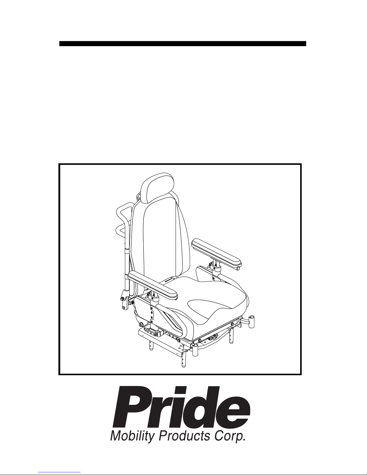
BASIC OPERATION INSTRUCTIONS
Euro Seat 2
ACN# 088 609 661
Page 2
Euro Seat 2 www.pridemobility.com
2 Basic Operation Instructions
SAFETY GUIDELINES
Copyright © 2010
Pride Mobility Products Corporation
INFMANU3835/Rev B/May 2010
WARNING! An authorized Pride Provider or a qualified
technician must perform the initial setup of this product
and must perform all of the instructions in this manual.
The symbols below are used throughout this owner's manual and on the
product to identify warnings and important information. It is very important
for you to read them and understand them completely.
WARNING! Indicates a potentially hazardous condition/
situation. Failure to follow designated procedures can
cause either personal injury, component damage, or
malfunction. On the product, this icon is represented as a
black symbol on a yellow triangle with a black border.
MANDATORY! These actions should be performed as
specified. Failure to perform mandatory actions can cause
personal injury and/or equipment damage. On the product,
this icon is represented as a white symbol on a blue dot
with a white border.
PROHIBITED! These actions are prohibited. These actions
should not be performed at any time or in any
circumstances. Performing a prohibited action can cause
personal injury and/or equipment damage. On the product,
this icon is represented as a black symbol with a red circle
and a red slash.
NOTE: These instructions are compiled from the latest specifications and
product information available at the time of publication. We reserve the
right to make changes as they become necessary. Any changes to our
products may cause slight variations between the illustrations and explanations in this manual and the product you have purchased. The latest/
current version of this manual is available on our website.
Page 3

www.pridemobility.com Euro Seat 2
Basic Operation Instruct io ns 3
LABEL INFORMATION ................................................................. 4
INTRODUCTION ........................................................................... 5
THE EURO SEAT 2 ...................................................................... 7
PRECAUTIONARY GUIDELINES ................................................ 7
COMFORT ADJUSTMENTS ......................................................... 9
CONTROLLER POSITION .......................................................... 18
POSITIONING BELT ................................................................... 20
POWER ACCESSORIES ............................................................ 22
CARE AND MAINTENANCE ...................................................... 23
WARRANTY ............................................................................... 23
APPENDIX I - SPECIFICATIONS .............................................. 24
TABLE OF CONTENTS
Page 4
4 Basic Operation Instructions
Euro Seat 2 www.pridemobility.com
PRODUCT SAFETY SYMBOLS
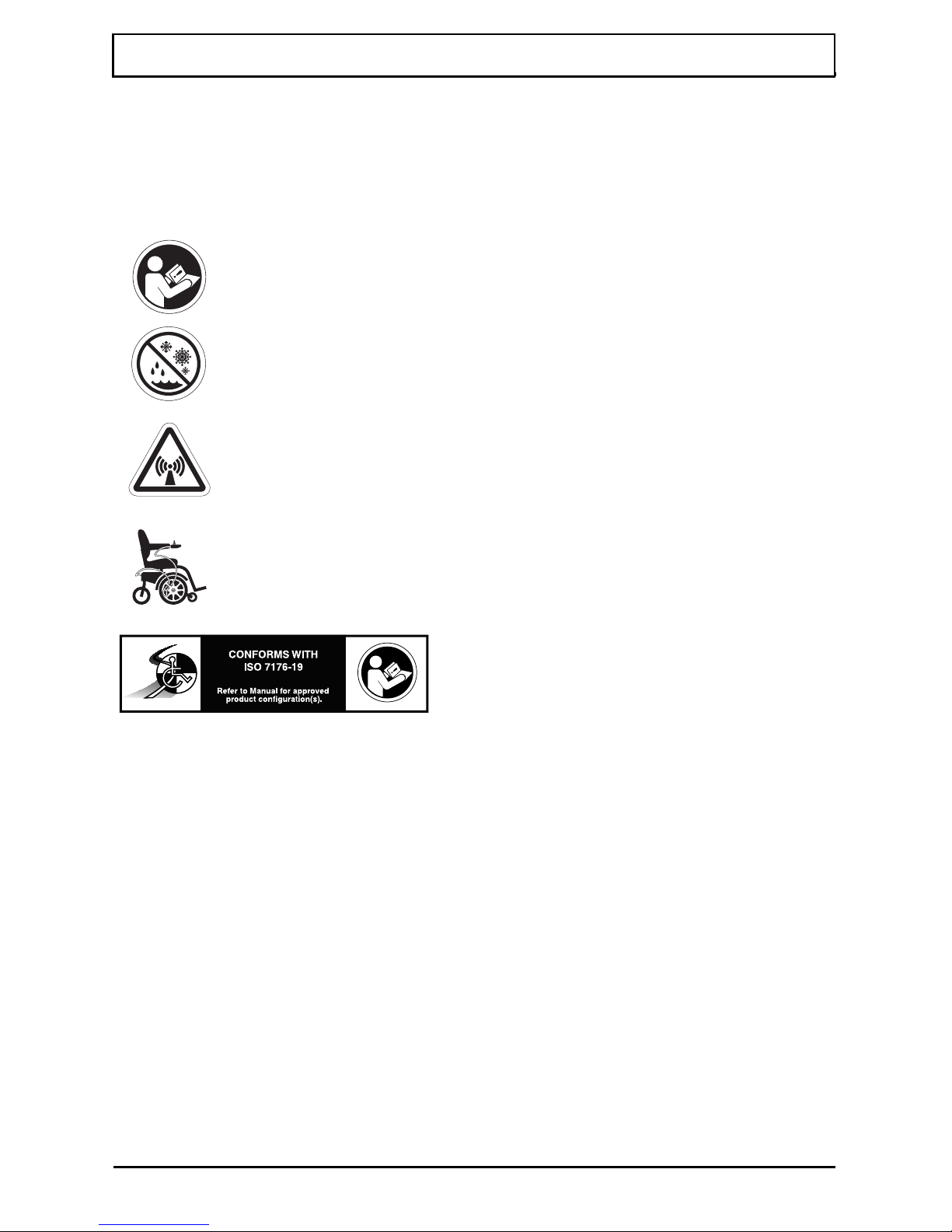
The symbols below are used on the seating system to identify warnings,
mandatory actions, and prohibited actions. It is very important for you to
read and understand them completely.
LABEL INFORMATION
Read and follow the information in the owner’s manual.
Avoid exposure to rain, snow, ice, salt, or standing water
whenever possible. Maintain and store in a clean and dry
condition.
EMI-RFI - This product has been tested and passed at an
immunity level of 20 V/m.
Use correct tie-down points for controller harness to
prevent the harness from getting caught in the drive tires,
pinched in the seat frame, or damaged when passing
through doorways.
Indicates that tested and
approved seating system
conforms to ISO 7176-19
requirements.
Page 5

www.pridemobility.com Euro Seat 2
Basic Operation Instruct io ns 5
INTRODUCTION
WELCOME to Pride Mobility Products (Pride). The product you have
purchased combines state-of-the-art components with safety, comfort, and
styling in mind. We are confident that the design features will provide you
with the conveniences you expect during your daily activities.
Understanding how to safely operate and care for this product should bring
you years of trouble free operations and service.
Read and follow all instructions, warnings, and notes in this manual before
attempting to operate your product for the first time. You must also read all
instructions, warnings, and notes contained in any supplemental instructional booklets for the controller, front riggings, and/or seating system that
accompanied your power chair before initial operation. Your safety
depends upon you, as well as your provider, caretaker, or healthcare professional in using good judgement.
This manual is to be used in addition to the power base owner’s manual that
came with your power chair. If there is any information in this manual which
you do not understand, or if you require additional assistance for setup or
operation, please contact your authorized Pride Provider. Failure to follow
the instructions, warnings, and notes in this manual and those located
on your Pride product can result in personal injury and/or product
damage and will void Pride’s product warranty.
PURCHASER’S AGREEMENT
By accepting delivery of this product, you promise that you will not change,
alter, or modify this product or remove or render inoperable or unsafe any
guards, shields, or other safety features of this product; fail, refuse, or
neglect to install any retrofit kits from time to time provided by Pride to
enhance or preserve the safe use of this product.
INFORMATION EXCHANGE
We want to hear your questions, comments, and suggestions about this
manual. We would also like to hear about the safety and reliability of your
new Pride product, and about the service you received from your authorized
Pride Provider.
Page 6

6 Basic Operation Instructions
Euro Seat 2 www.pridemobility.com
Please notify us of any change of address, so we can keep you apprised of
important information about safety, new products, and new options that can
increase your ability to use and enjoy your Pride product.
NOTE: If you ever lose or misplace your product registration card or your
copy of this manual, contact us and we will be glad to send you a new one
immediately.
My Authorized Pride Provider Is:
Name:_______________________________________________________
Address:______________________________________________________
Phone Number:________________________________________________
Purchase Date:________________________________________________
Page 7

Basic Operation Instructi o ns 7
www.pridemobility.com Euro Seat 2
THE EURO SEAT 2
The Euro Seat 2 is a unique seating system designed specifically for the Pride
Power Chair. It is fully adjustable to meet the individual needs of the user, and
it is mounted to a Pride power base to provide maximum maneuverability.
Reusable hook and loop fasteners are included in your owner’s package for use
in attaching the seat cushion to the seat base. These fasteners are not intended for
use on cushions with anti-skid material, as they may damage the seat cushion.
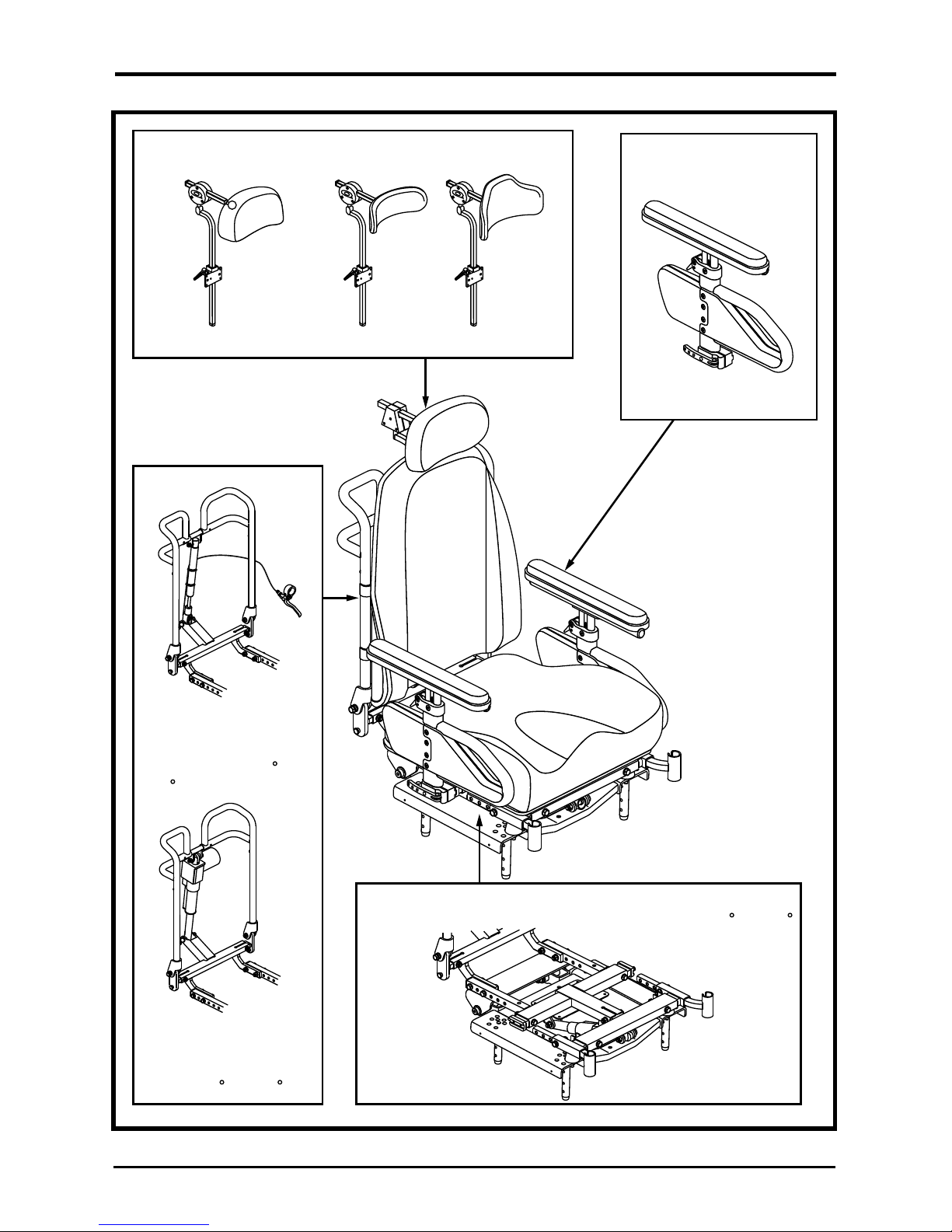
Figure 1 provides information on Euro Seat 2 components. Use this
diagram to familiarize yourself with the function and location of each
component before using the Euro Seat 2.
PRECAUTIONARY GUIDELINES
Before using the Euro Seat 2, please read the following. These guidelines are
provided for your benefit and will aid you in the safe operation of the seating system.
Turn off the power before you are seated in the Euro Seat 2.
Always have assistance when you are being seated in the Euro Seat 2.
Follow all of the procedures and heed the warnings as explained in your
power chair owner’s manual.
WARNING! Should the fittings on your Euro Seat 2 become
loose, report the problem immediately to your authorized
Pride Provider.
WARNING! Pride does not recommend using the Euro Seat
2 as a seat in a motor vehicle. The user should transfer into
the vehicle seat and use the vehicle-installed belt restraint
system if and whenever feasible. If your mobility device is
equipped with a manufacturer-installed transit securement
system, please refer to the supplemental safety
information provided with your mobility device.
WARNING! Do not exceed the weight capacity listed in your power
chair owner’s manual or 136 kg (300 lbs.), whichever is less.
WARNING! Extreme temperatures can affect the
temperature of Euro Seat 2 components and may cause
skin irritation. Use caution when your power chair has been
used or stored in an extremely hot or cold environment.
WARNING! Standard foam cushions and other body supports
are not designed for the relief of pressure. If you suffer from
pressure sores, or if you are at risk for pressure sores, you
may need a specialized seating system or a device to
control your posture. Consult your doctor or therapist to
determine if you need such a device for your well being.
Page 8
8 Basic Operation Instructions
Euro Seat 2 www.pridemobility.com
ARMRESTS
RECLINE BACKS
DROP-IN ARMREST
POWER TILT
With this option, the seat angle can be adjusted between 90 and 120
HEADRESTS
Available in two basic styles:
EURO HEADREST QUANTUM HEADREST
MANUAL RECLINE
With this option, the
seatback can be manually
adjusted between 90 and
135
POWER RECLINE
With this option, the
seatback can be adjusted
between 90 and 135
Figure 1. Euro Seat 2 Components
Page 9
Basic Operation Instructi o ns 9
www.pridemobility.com Euro Seat 2
COMFORT ADJUSTMENTS
There are several adjustments that can be made to the Euro Seat 2 to increase
your comfort, such as seat height and angle, armrest position, and controller
position.
WARNING! The center of gravity of your seating system was
factory set to a position that meets the needs of the
demographic majority of users. Your authorized Pride Provider
has evaluated your seating system and made any necessary
adjustments to suit your specific requirements. Do not change
your seating configuration without first contacting Pride
Mobility Products or your authorized Pride Provider.
WARNING! Some power chair components are heavy. You
may need assistance to lift or carry them. Please refer to
the specifications table for specific component weights
before you disassemble the power chair.
WARNING! Remove the occupant from the power chair
before making any adjustments.
WARNING! Be sure that the controller’s power is turned off
and the power chair is not in freewheel mode before
performing any adjustment procedures.
You may need the following to make comfort adjustments:
metric/standard socket set and ratchet
adjustable wrench
metric/standard hex key set
Seat Height and Angle Adjustment
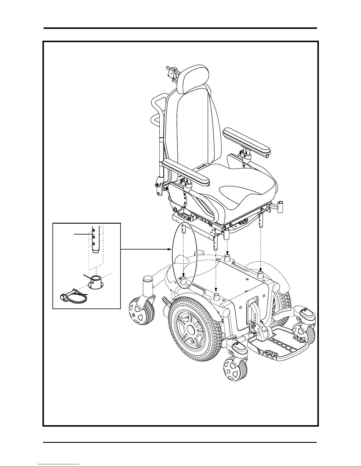
The Euro Seat 2 is usually connected to a power base with four steel towers.
You can change the seat height by raising these towers. If you raise or lower
only one set of seat towers (front or rear), you can also change the seat base
angle.
To change the seat height or seat angle:
1. Remove the retaining pin from each of the four seat mount connectors.
See figure 2.
2. Raise or lower each seat tower to the desired position. To change the
angle, set either the front or rear seat towers higher or lower than the
other.
3. Reinstall the retaining pin into each seat mount connector.
Page 10
10 Basic Operation Instruc t io ns
Euro Seat 2 www.pridemobility.com
Figure 2. Seat Height/Angle Adjustment
SEAT
TOWER
SEAT
MOUNT
CONNECTOR
RETAINING
PIN
Page 11
Basic Operation Instructi o ns 11
www.pridemobility.com Euro Seat 2
90
Manual Recline Seatback
Adjustment
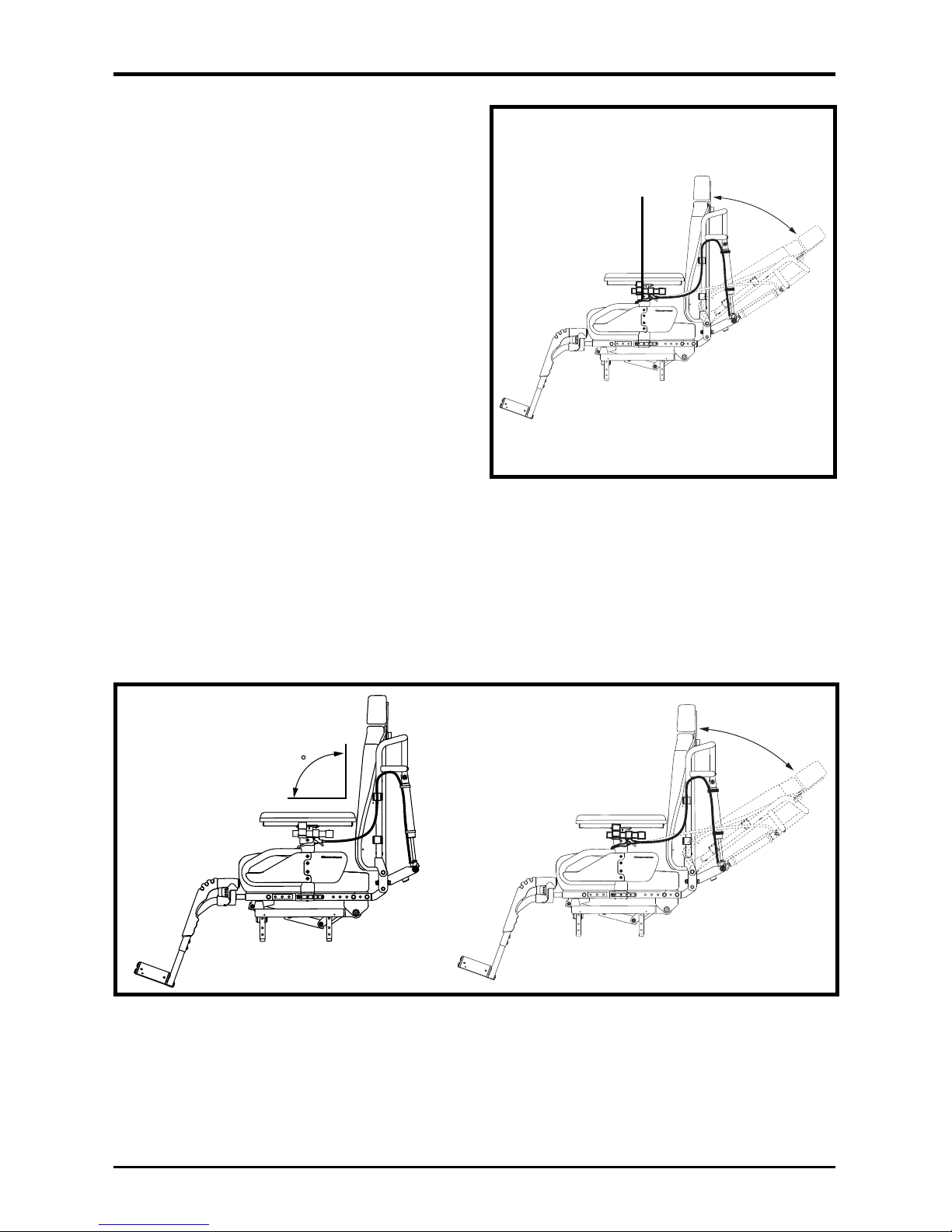
Your seat may be equipped with a
manual recline lever that allows
you to adjust the seatback angle
from the minimum recline position
(90° from the seat base) to the maximum recline position (135° from
the seat base). See figures 3 and 4.
To adjust the seatback angle:
1.
With your back pressed firmly
against the seatback, squeeze the
manual recline lever mounted to
the armrest.
See figure 3.
2.
Set the seatback at the desired
angle by leaning forward or back.
3. Release the manual recline
lever when the seatback is at the
desired angle.
Figure 3. Manual Recline Seatback
Adjustment
MANUAL RECLINE
LEVER
Figure 4. Minimum and Maximum Manual Recline Angles
Page 12
12 Basic Operation Instruc t io ns
Euro Seat 2 www.pridemobility.com
Seat Angle (Dump) Adjustment
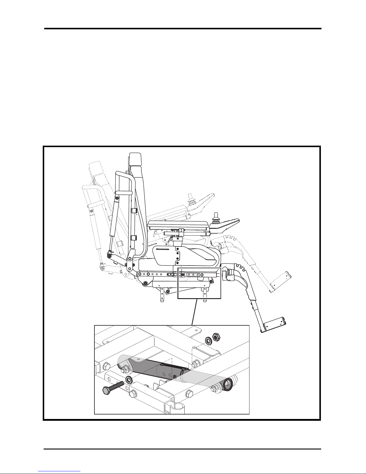
Your seat may be equipped with a mechanism that allows you to adjust the
seat angle (dump) from -5° to +10° in 2.5° increments.
To adjust the seat angle (dump):
1. Remove the occupant from the power chair.
2. Remove the seat angle adjustment bolt. See figure 5.
3. Adjust the seat to the desired angle.
4. Reinstall the seat angle adjustment bolt.
Figure 5. Seat Angle (Dump) Adjustment
Page 13
Basic Operation Instructi o ns 13
www.pridemobility.com Euro Seat 2
Seat Width Adjustment
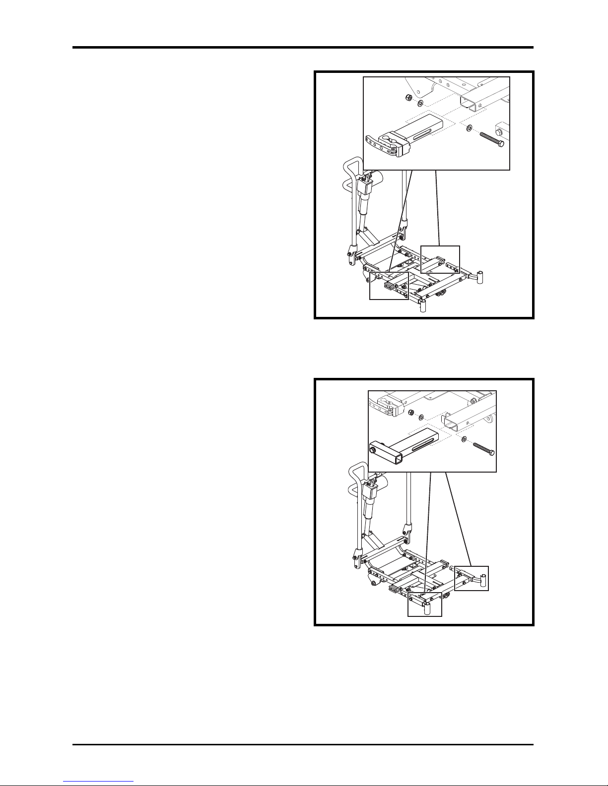
You can adjust the seat width from
40.6 to 50.8 cm (16 in. to 20 in.).
To adjust the seat width:
1. Remove the seat cushion.
2. Loosen the armrest receiver
hardware. See figure 6.
3. Reposition the armrest receiver
to the desired seat width.
4. Tighten the armrest receiver
hardware.
5. Adjust the width of the other
armrest if necessary.
6. Replace the seat cushion.
Leg Rest Width Adjustment
You can adjust the leg rest width from
40.6 to 50.8 cm (16 in. to 20 in.).
To adjust the leg rest width:
1. Remove the seat cushion.
2. Loosen the leg rest receiver
hardware. See figure 7.
3. Reposition the leg rest receiver
to the desired seat width.
4. Tighten the leg rest receiver
hardware.
5. Adjust the width of the other leg
rest if necessary.
6. Replace the seat cushion.
Figure 6. Seat Width Adjustment
Figure 7. Leg Rest Width Adjustment
Page 14
14 Basic Operation Instruc t io ns
Euro Seat 2 www.pridemobility.com
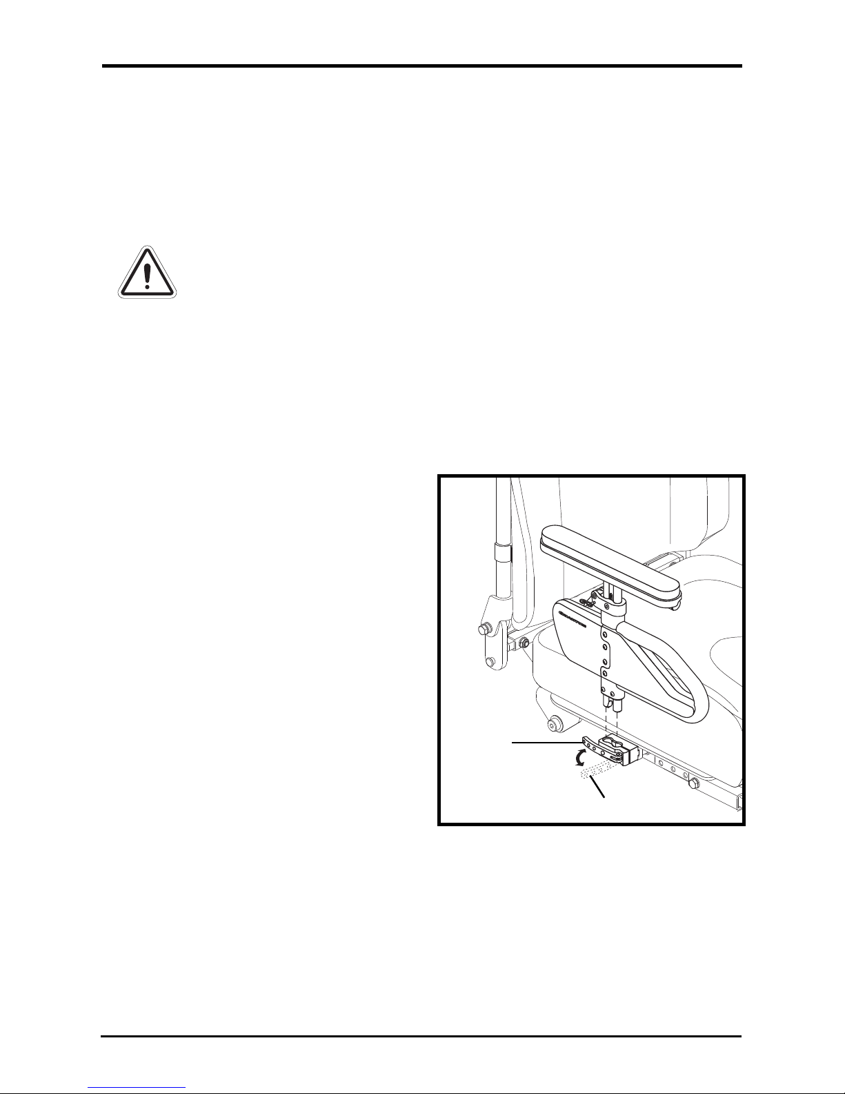
Figure 8. Armrest Removal/Installation
Armrest Height Adjustment
Armrest height adjustments can be
made on both the top and the bottom
of the armrest. The total height
adjustment range is 15.24 cm (6 in.)
from 27.94–43.18 cm (11–17 in.).
This range is measured from the
seat pan to the top of the armrest
pad.
Top height adjustments do not
require any tools. The top height
adjustment range is 7.62 cm (3 in.)
in 0.95 cm (3/8-in.) increments. The
bottom height adjustment range is
7.62 cm (3 in.) in 2.54 cm (1-in.)
increments.
To remove the armrest assembly:
1. Rotate the armrest lock lever
forward. See figure 8.
2. Lift up the armrest assembly.
WARNING! Do not attempt to lift or move your power chair
or seating system by any of its removable parts, including
the armrests, front riggings, seat cushions, seatback,
shrouds, or controller. Use only solid, non-removable frame
components to lift or move your power chair or seating
system.
WARNING! Avoid putting all of your weight on the Euro Seat
2 armrests and do not use the armrests for weight bearing
purposes, such as transfers. Such use may cause the
power chair to tip, resulting in a fall from the power chair
and personal injury.
WARNING! The controller and controller bracket are nonload bearing items on your seating system. Do not use the
controller or controller bracket for weight bearing puposes,
such as transfers. Such use may cause damage to these
components, resulting in a fall from the seating system and
personal injury.
LOCKED
POSITION
UNLOCKED
POSITION
Page 15
Basic Operation Instructi o ns 15
www.pridemobility.com Euro Seat 2
To install the armrest assembly:
1. Place the armrest assembly into
the armrest lock. See figure 8.
2. Rotate the armrest lock lever
rearward.
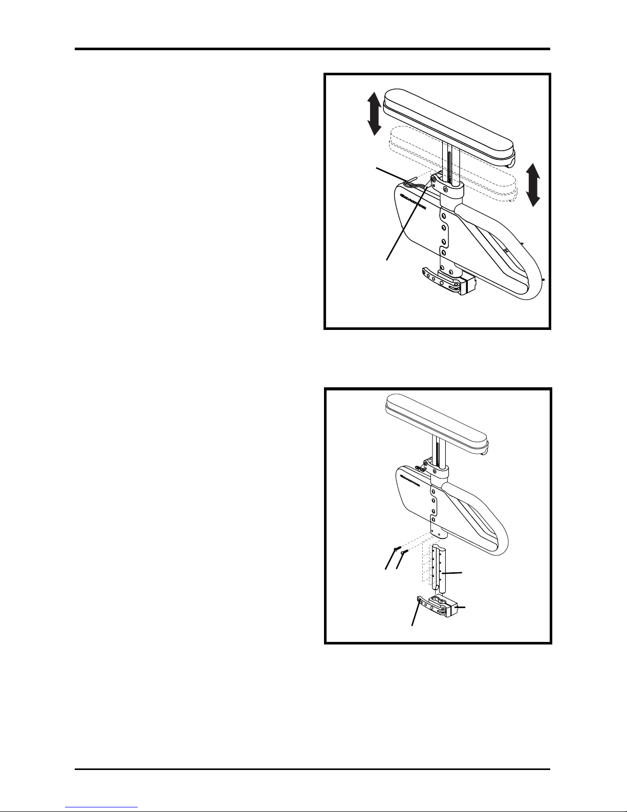
To adjust the top height:
1. If present, remove the optional
locking pin. See figure 9.
2. Pull the armrest up to raise, or
press the release lever to lower the
armrest to the desired height.
3. If applicable, reinsert the locking
pin.
4. Repeat for the other armrest if
necessary.
To adjust the bottom height:
1. Remove the two button head
screws from the detent bar. See
figure 10.
2. Slide the armrest up or down.
3. Line up the holes in the armrest.
4. Reinstall the two button head
screws into the detent bar.
5. Repeat for the other armrest if
necessary.
Figure 9. Armrest Top Height
Adjustment
LOCKING PIN
ARMREST HEIGHT
ADJUSTMENT LEVER
Figure 10. Armrest Bottom Height
Adjustment
BUTTON HEAD
SCREWS
ARMREST LOCK LEVER
DETENT BAR
ARMREST LOCK
Page 16
16 Basic Operation Instruc t io ns
Euro Seat 2 www.pridemobility.com
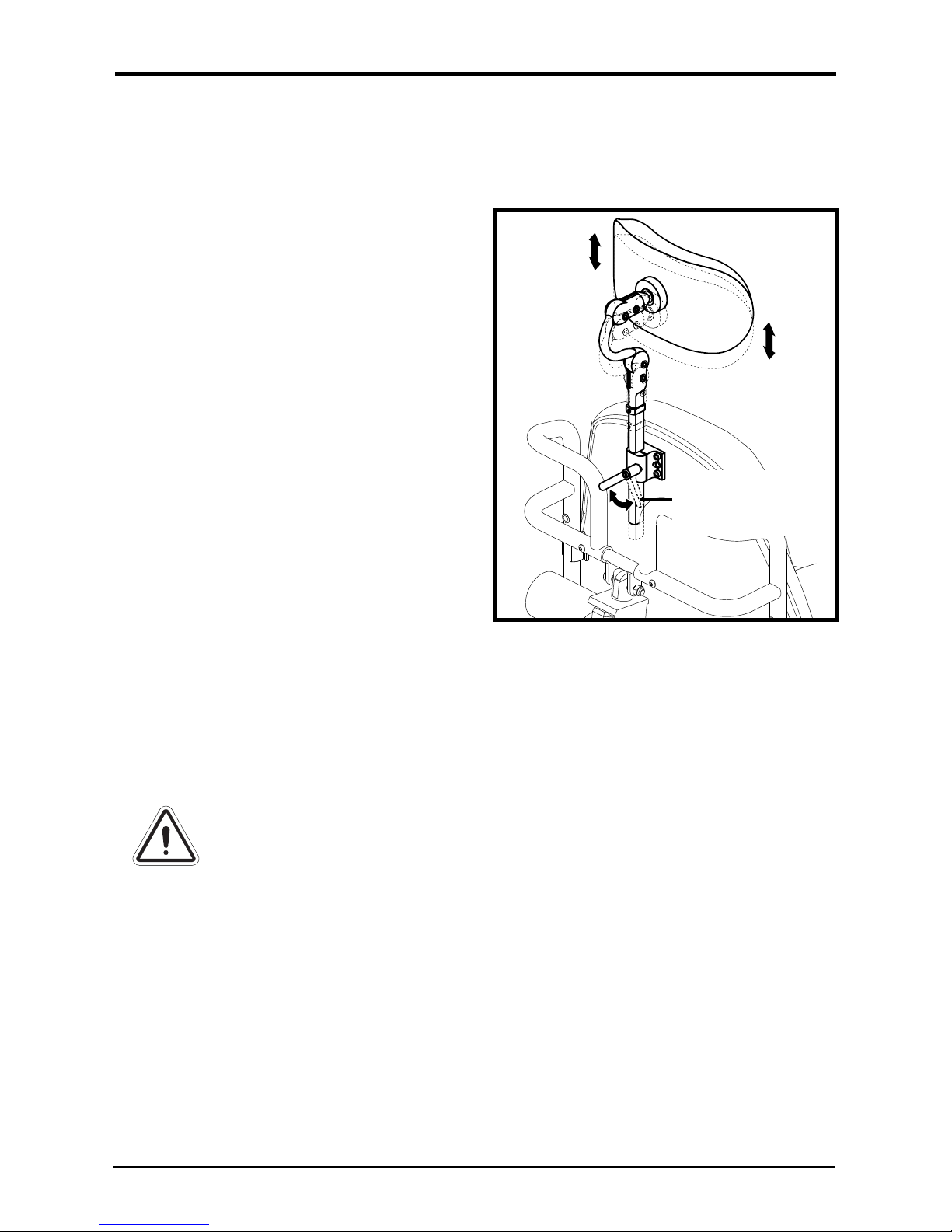
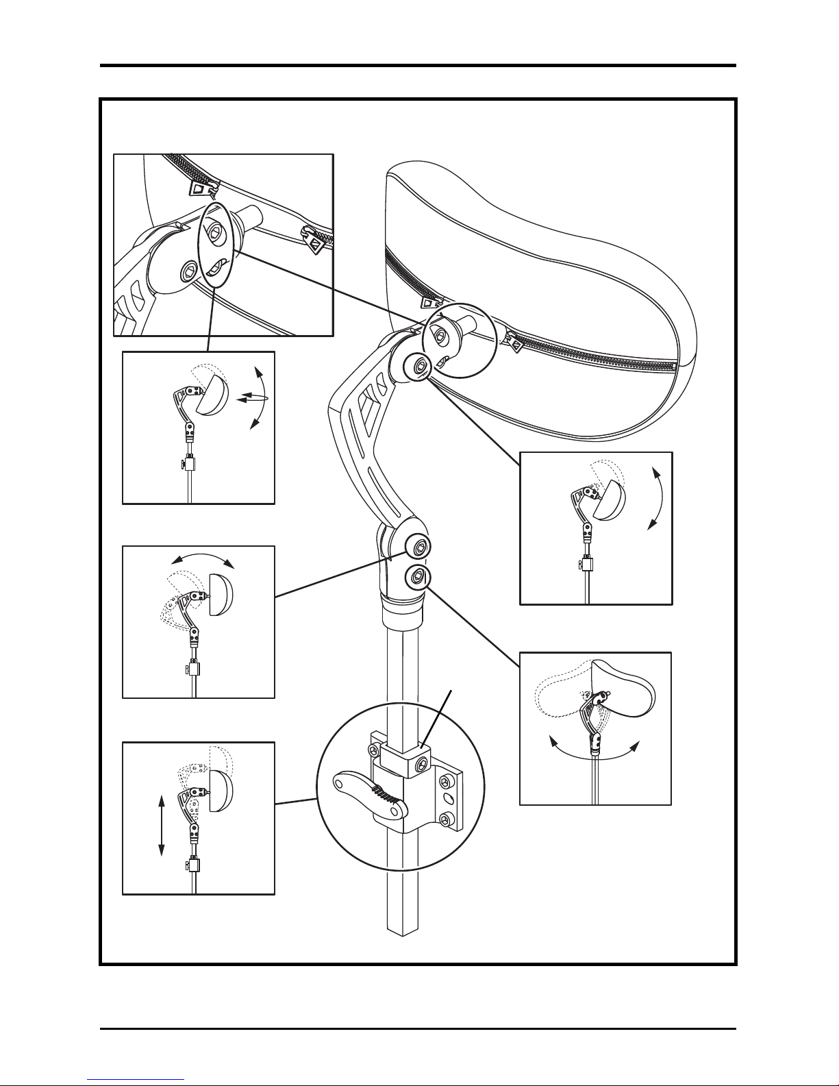
To adjust the Euro-style headrest
height:
1. Loosen the headrest receiver lock
lever. See figure 11.
2. Slide the headrest up or down to
the desired position.
3. Tighten the headrest receiver
lock lever to secure the headrest
to the desired position.
To adjust the height, depth, or
angle of the headrest:
1. Loosen the adjustment screws
that correspond to the desired
adjustments. See figure 12.
2. Position the headrest to the
desired position.
3. Tighten the adjustment screws.
Figure 11. Euro-style Headrest
Height Adjustment
HEADREST
RECEIVER LOCK
LEVER
Headrest Adjustment
Your seat is equipped with either a Euro-style or Quantum-style headrest.
NOTE: Once adjustments have been made and the headrest is in the
desired position, make sure that all of the hardware is tight.
WARNING! Do not extend the overall headrest height more
than 17.78 cm (7 in.) above the headrest bracket.
Page 17
Basic Operation Instructi o ns 17
www.pridemobility.com Euro Seat 2
Figure 12. Quantum-style Headrest Adjustments
HEADREST
BRACKET
HEADREST ANGLE ADJUSTMENT
HEADRESTL ANGLE ADJUSTMENT
VERTICAL ANGLE ADJUSTMENT
HORIZONTAL ANGLE
ADJUSTMENT
HEIGHT ADJUSTMENT
Page 18
18 Basic Operation Instruc t io ns
Euro Seat 2 www.pridemobility.com
CONTROLLER POSITION
You can position the controller for either left-hand or right-hand use. You
can also adjust the extension of the controller from the armrest.
MANDATORY! Prevent controller harness damage! Avoid
routing the controller harness on the outside of the armrest
pad. Route the harness under the armrest or toward the
inside of the armrest pad. Use correct tie-down points for
the controller harness to prevent the harness from getting
caught in the drive tires, pinched in the seat frame, or
damaged when passing through doorways.
NOTE: Your controller will be attached either by a mounting block or a
figure 8 assembly. Be sure to follow the correct set of instructions below
when changing the position of your controller.
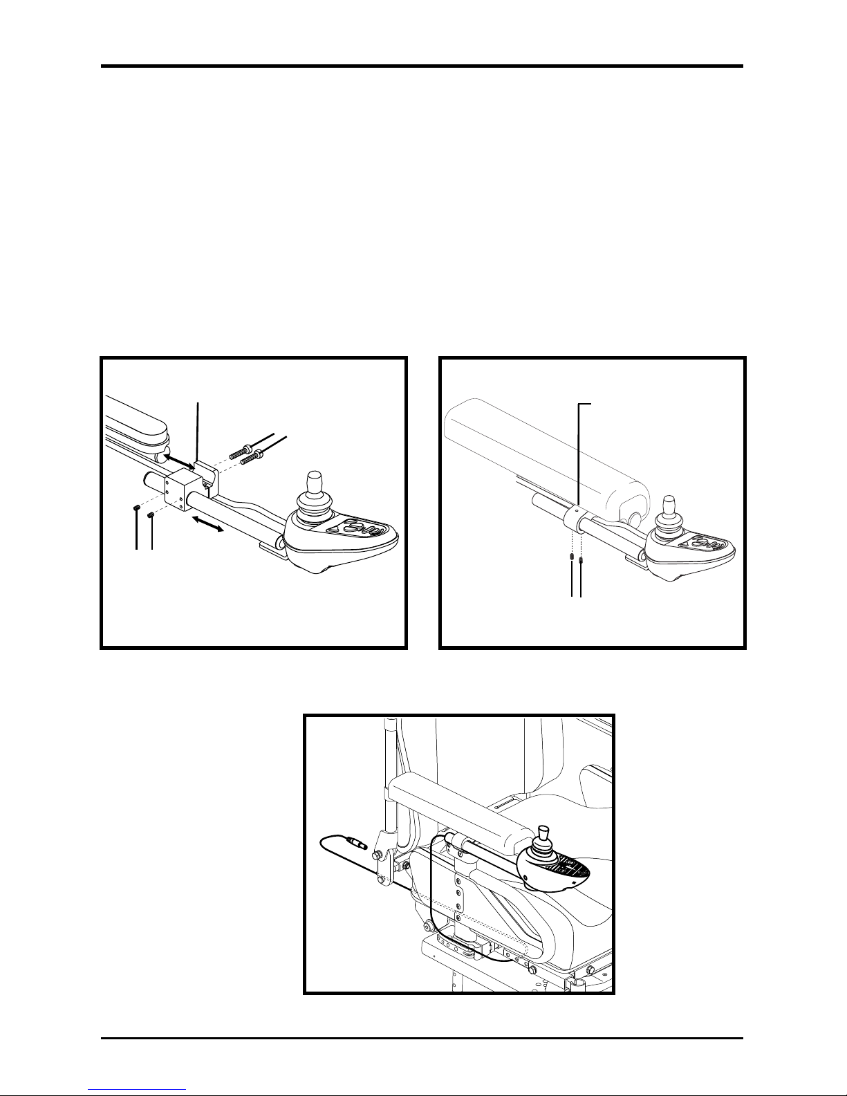
To change the controller position in a mounting block:
1. Turn off the power to the controller.
2. Unplug the controller connector from the power base. Refer to your
power chair owner’s manual.
3. Remove any wire ties securing the controller harness to the armrest.
4. Loosen the mounting screws in the controller mounting block. See
figure 13.
5. Move the controller mounting block and controller to the other armrest
and tighten the mounting screws.
6. Use wire ties to secure the controller harness and the manual recline
lever cable to the armrests.
7. Route the controller harness along the seat frame and reconnect the
controller to the power base. See figure 15.
To change the controller position in a figure 8 assembly:
1. Turn off the power to the controller.
2. Unplug the controller connector from the power base. Refer to your
power chair owner’s manual.
3. Remove any wire ties securing the controller harness to the armrest.
4. Loosen the setscrews on the figure 8 clamp assembly located on the
armrest. See figure 14.
5. Slide the controller out of the loosened clamp assembly.
6. Loosen the setscrews on the clamp assembly on the other armrest.
7. Remove the manual recline lever assembly and insert it into the clamp
assembly on the opposite armrest. See figure 3.
8. Tighten the setscrews to secure the manual recline lever assembly in the
figure 8 clamp.
9. Insert the controller into the remaining open clamp assembly.
10. Tighten the setscrews to secure the controller in the figure 8 clamp.
Page 19
Basic Operation Instructi o ns 19
www.pridemobility.com Euro Seat 2
11. Use wire ties to secure the controller harness and the manual recline
lever cable to your seating system.
12. Route the controller harness along the seat frame and reconnect the
controller. See figure 15.
To change the controller extension:
1. Turn off the power to the controller.
2. Loosen the setscrews on the mounting assembly located on the armrest.
See figure 13 or 14.
3.
Slide the controller into or out of the mounting assembly to the desired position.
4. Tighten the setscrews to secure the controller in the mounting assembly.
Figure 13. Controller Position
Adjustment - Mounting Block
Figure 15. Harness Routing
SETSCREWS
FIGURE 8
CLAMP
ASSEMBLY
Figure 14. Controller Position
Adjustment - Figure 8 Assembly
MOUNTING BLOCK
MOUNTING SCREWS
SETSCREWS
Page 20

20 Basic Operation Instruc t io ns
Euro Seat 2 www.pridemobility.com
POSITIONING BELT
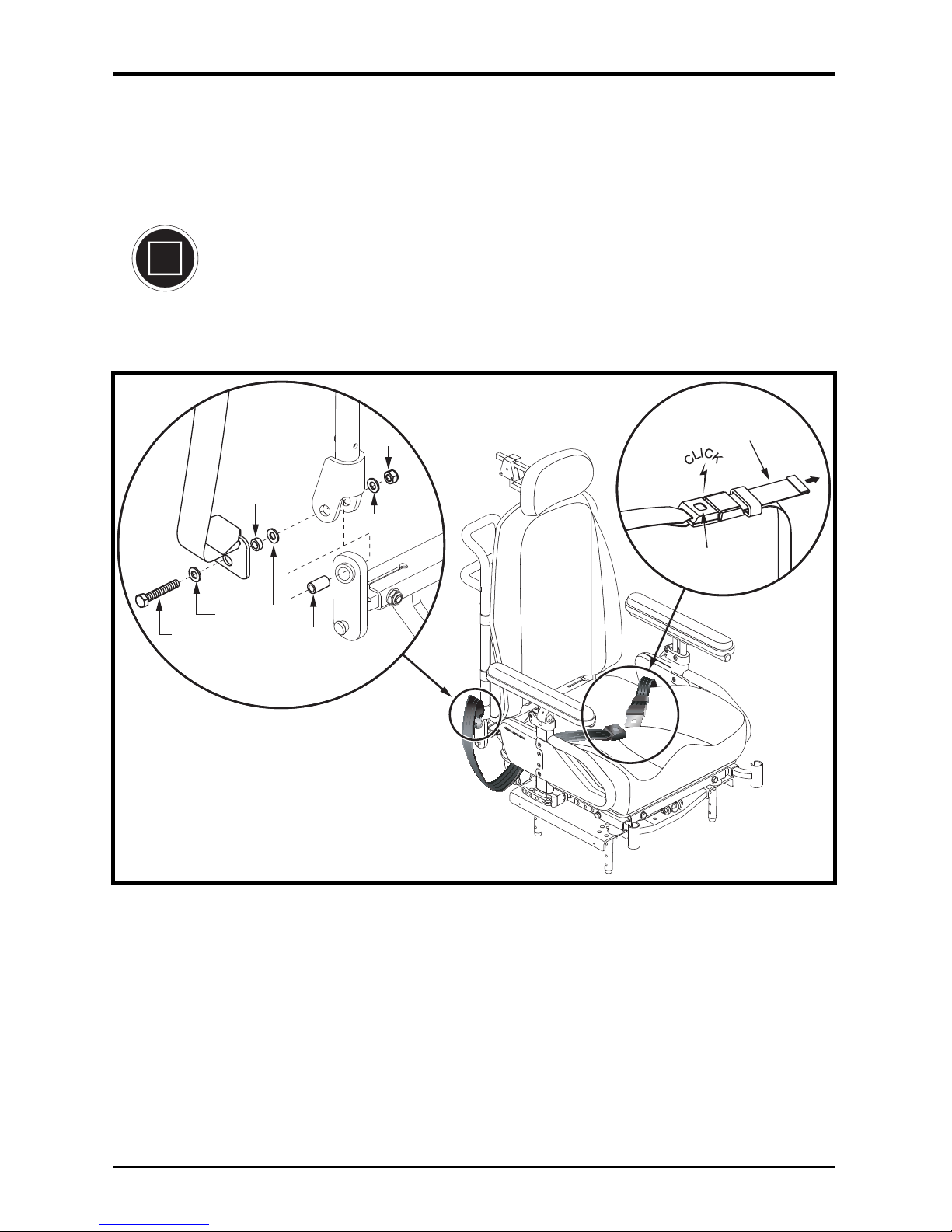
Your Euro Seat 2 may be equipped with a positioning belt that can be
adjusted for operator comfort. See figure 16. The positioning belt is
designed to support the operator so that he/she does not slide down or
forward in the seat. The positioning belt is not designed for use as a
restraining device in a motor vehicle.
WARNING! The positioning belt is not designed for use as a
seat belt in a motor vehicle. Nor is your power chair
suitable for use as a seat in any vehicle. Anyone traveling
in a vehicle should be properly belted into seats approved
by the vehicle manufacturer.
To install the positioning belt:
1. Insert the screw through the washer and the mounting tab at the end of
the positioning belt. See figure 16.
2. Install the screw through the steel spacer, washer, and then the seatback
including the large zinc spacer.
3. Install the washer and nut to the assembly and then tighten the nut using
two adjustable wrenches.
4. Repeat steps 1-3 for the other side.
To adjust the positioning belt:
1. Once seated, insert the metal tab on one side of the belt into the plastic
housing on the opposite side until you hear a click.
2. Pull the excess strap attached to the metal tab until it is secure, but not
so tight as to cause discomfort.
Page 21
Basic Operation Instructi o ns 21
www.pridemobility.com Euro Seat 2
PULL TO
TIGHTEN
PRESS TO
RELEASE
STEEL
SPACER
NUT
ZINC
SPACER
SCREW
WASHER
WASHER
Figure 16. Positioning Belt Attachment
To release the positioning belt:
1. Press the push button mechanism on the plastic housing.
MANDATORY! Make sure the positioning belt is properly
secured to the seating system and is adjusted for operator
comfort before each use.
MANDATORY! Inspect the positioning belt for loose or
damaged parts before each use of the power chair. If you
discover a problem, contact your authorized Pride Provider
for maintenance and repair.
Page 22
22 Basic Operation Instruc t io ns
Euro Seat 2 www.pridemobility.com
135
90
120
90
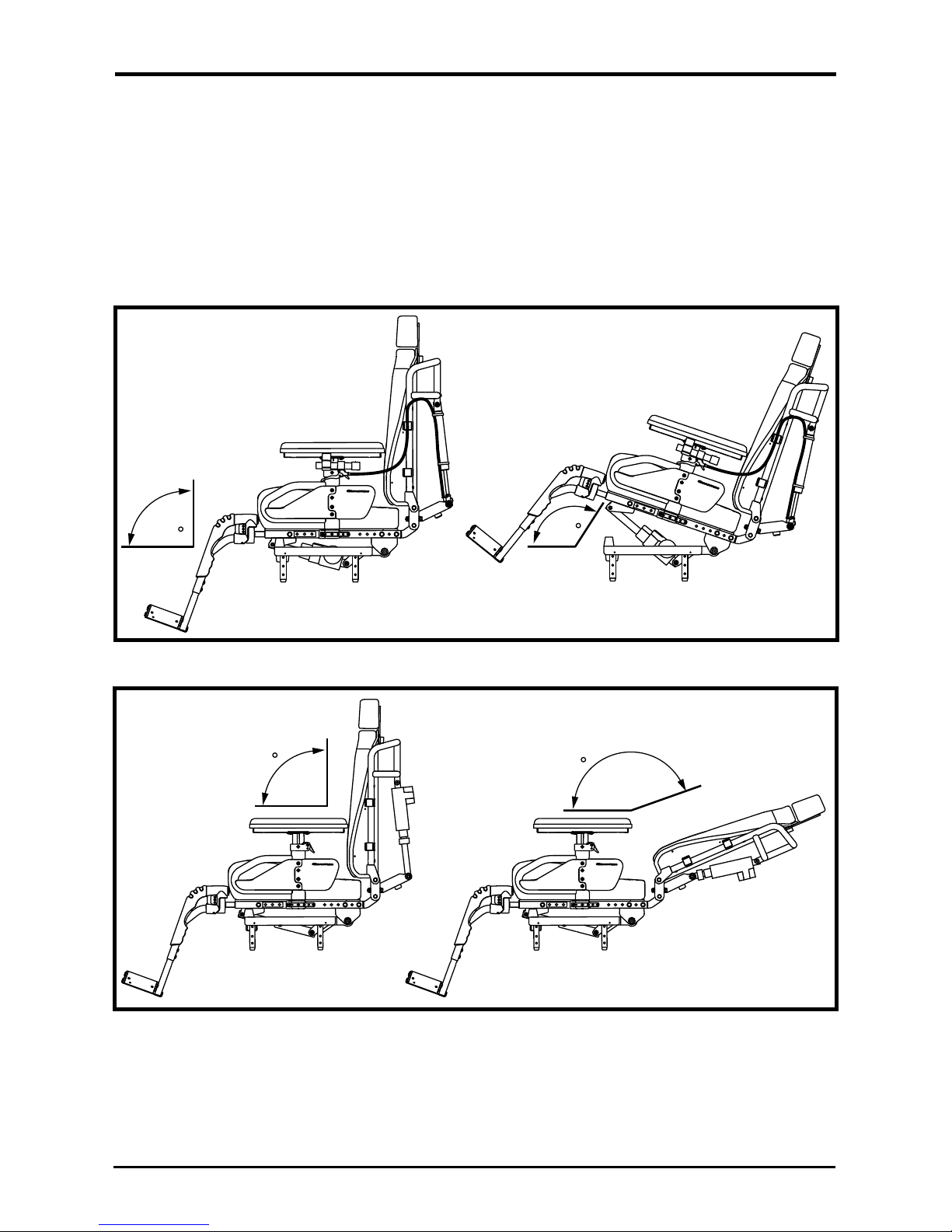
Figure 18. Euro Seat 2 Power Recline Range of Motion
NOTE: When the seat is tilted or reclined past 120°, an inhibit switch will
cut power to the motors of your power chair. Returning the seat to an
angle of less than 120° degrees will restore power to the motors.
POWER ACCESSORIES
Your Euro Seat 2 may be equipped with optional power positioning such as
a power tilt, power recline, and power front riggings. Refer to the
supplemental controller information supplied with your power chair
owner’s manual for instructions on how to operate power accessories. See
figures 17 and 18 for range of motion of the power tilt and recline.
Figure 17. Euro Seat 2 Power Tilt Range of Motion
Page 23
Basic Operation Instructi o ns 23
www.pridemobility.com Euro Seat 2
CARE AND MAINTENANCE
Make sure all hardware is secured properly, but do not overtighten any
hardware.
To clean the Euro Seat 2, wipe it with a cloth dampened with mild soap
and water. Thoroughly dry the unit before using.
PROHIBITED! Avoid exposure to rain, snow, ice, salt, or
standing water whenever possible. Maintain and store in a
clean and dry condition.
WARNING! Pride strongly recommends that you do not
smoke cigarettes while seated in your Euro Seat 2,
although the seating system has passed the necessary
testing requirements for cigarette smoking. You must
adhere to the following safety guidelines if you decide to
smoke cigarettes while seated in your seating system.
Do not leave lit cigarettes unattended.
Keep ashtrays a safe distance from the seat cushions.
Always make sure cigarettes are completely
extinguished before disposal.
WARNING! Never use any chemicals to clean a vinyl seat,
as they may cause the seat to become slippery or dry out
and crack. Use soapy water and dry the seat thoroughly.
WARRANTY
Refer to your power base owner’s manual for warranty information.
Page 24
24 Basic Operation Instruc t io ns
Euro Seat 2 www.pridemobility.com
APPENDIX I - SPECIFICATIONS
Euro Seat 2 Specifications Table
Seat Weight: Manual Recline:
16 in. seat: 29.71 kg (65.5 lbs.) Sling Back
18 in. seat: 35.61 kg (78.5 lbs.) Solid Back
20 in. seat: 36.74 kg (81.0 lbs.) Solid Back
Power Tilt:
16 in. seat: 31.07 kg (68.5 lbs.) Sling Back
18 in. seat: 37.19 kg (82.0 lbs.) Solid Back
20 in. seat: 38.33 kg (84.5 lbs.) Solid Back
Power Recline:
16 in. seat: 36.51 kg (80.5 lbs.) Solid Back
18 in. seat: 36.97 kg (81.5 lbs.) Solid Back
20 in. seat: 38.10 kg (84.0 lbs.) Solid Back
Power Tilt/Power Recline:
16 in. seat: 38.10 kg (84.0 lbs.) Solid Back
18 in. seat: 38.56 kg (85.0 lbs.) Solid Back
20 in. seat: 39.69 kg (87.5 lbs.) Solid Back
Seat Dimensions:
16 in. x 16 in., 16 in. x 18 in.,18 in. x 18 in., 20 in. x 20 in.
Back Height: 22 in.
Seat Upholstery: Vinyl
Armrests: Drop-in
Headrests: Euro-style
Quantum Headrest (optional; 2 styles)
Weight Capacity: 136 kg (300 lbs.)
Page 25

Basic Operation Instructi o ns 25
www.pridemobility.com Euro Seat 2
NOTES
Page 26

26 Basic Operation Instruc t io ns
Euro Seat 2 www.pridemobility.com
NOTES
Page 27

Basic Operation Instructi o ns 27
www.pridemobility.com Euro Seat 2
NOTES
Page 28

*INFMANU3835*
Pride Mobility Products Corporation
182 Susquehanna Avenue
Exeter, PA 18643-2694
USA
Pride Mobility Products Company
380 Vansickle Road Unit 350
St. Catharines, Ontario L2R 6P7
Canada
Pride Mobility Products Ltd.
32 Wedgwood Road
Bicester, Oxon OX26 4UL
UK
Pride Mobility Products Australia Pty. Ltd.
21 Healey Road
Dandenong, 3175
Victoria, Australia
Pride Mobility Products Italia S.r.l.
Via del Progresso - ang. Via del Lavoro
Loc. Prato della Corte
00065-Fiano Romano (RM)
Pride Mobility Products Europe B.V.
Castricummer Werf 26
1901 RW Castricum
The Netherlands
 Loading...