

Page 1
Price®Pump Co.
INSTALLATION, OPERATING
AND
MAINTENANCE MANUAL
3” AIR OPERATED DIAPHRAGM PUMPS
METALLIC, BOLTED
MODELS: 3 AOD-XXXX-B
ALL ELASTOMERS
Price®Pump Company
P.O.Box
Sonoma, CA 95476
Tel: 707-938-8441
Fax 707-938-0764
Email: [email protected]
PLEASE FILL IN DATA
FROM YOUR PUMP
NAMEPLATE
Pump Model______________________
Spec. No._________________________
Serial No._________________________
RETAIN MANUAL
FOR REFERENCE
IN-AOD-300M-B rev. -
Page 2
IN-AOD-300M-B rev. -Page - 2
Congratulations
You are now the owner of a Price® Pump Co. Air Operated Diaphragm Pump. This pump was carefully
inspected and subjected to final performance tests before releasing for shipment. In order to achieve
maximum performance and reliability, please follow the simple instructions in this manual.
RECOMMENDED PRECAUTIONS
1. For satisfactory operation and safety, maximum inlet air pressure must not exceed 125 psi
(8.79kg/sq cm ).
2. No modifications, additions or deletions should be made to the pump without prior approval of
the factory.
3. Drain casing completely and flush with water before servicing pump handling volatile or
harmful liquids.
READ CAREFULLY THE CAUTION BELOW
CAUTION:
The performance of Price® pump is based on clear,
cold, fresh water with suction conditions as shown
on the performance curves. If used to pump other
liquids, pump performance may differ from rated
performance based on the different specific gravity ,
temperature, viscosity, etc. of the liquid being
pumped. A standard pump, however, may not be
safe for pumping alltypes of liquids, such as toxic,
volatile or chemical liquids, or liquids under
extreme temperatures or pressures.
Please consult Price® Pump catalogs as well as
local codes and general references to determine the
appropriate pumps for your particular application.
Since it is impossible for us to anticipate every
application of a Price® pump, if you plan to use the
pump for a non-water application, consult Price®
Pump beforehand to determine whether such
application may be proper and safe under the
circumstances. Failure to do so could result in
property damage or personal harm.
Visit Our Web Site
www.pricepump.com
Page 3

IN-AOD-300M-B rev. - Page - 3
INSTALLATION
Bolt pump to a mounting pad using appropriately
sized diameter bolts. Rubber vibration insulators
should be used between the pump mounting feet
and mounting pad to reduce pump vibrations and
stresses. In permanent installations the pump
should not be directly attached to rigid piping, but
instead should be connected through flexible hoses
or equivalent on both the suction and discharge.
This should be done to reduce pipe stresses and
vibrations which are characteristic of the
reciprocating nature of the pump. A surge
suppressor may be required on the discharge line of
the pump if further reduction in vibration or a
reduction of pulsation in the discharge flow is
desired.
If the pump is used in a submerged application a line
or hose should be attached to the pump air exhaust
to prevent liquid from entering the air valve when the
pump is shutdown or operating at low discharge
heads. CARE MUST BE EXERCISED WHEN
SUBMERGING THE PUMP IN CORROSIVE
PUMPING MEDIA.
Suction and discharge pipe size should be at least
equal to the inlet pipe diameter or larger. Larger, if
highly viscous liquid is to be pumped or long lengths
of pipe are used. When using suction hoses use the
non-collapsing reinforced type, since this pump is
capable of producing high vacuum at the suction
inlet.
SOLIDS-HANDLING CAPABILITY
Price® Pump Air Operated Diaphragm Pumps will
pass the following spherical solid sizes:
Model Size
3 AOD-XXXX-B 7/16” Dia. (11mm)
If the possibility exists that larger sized solids may
be suspended or carried along by the pumping
media. install a strainer on the suction line with
smaller sized holes than the allowable solid size.
This will prevent the larger solids from entering the
pump and interfering with operation of the pump ball
valves.
AIR SUPPLY
The inlet to the air valve is a female 3/4” NPT. The
air supply line should be sized accordingly so that
there is no restriction less than inlet pipe size.
NOTE: Longer air lines require larger diameters to
reduce the air system pressure loss and make
available required pressure and flow at the pump air
inlet. It is safe to use up to 125 psig (7.73 kg/sq cm)
for pumping requirements.
WARNING: DO NOT EXCEED 125 PSIG (8.79
KG/SQ CM) AIR SUPPLY PRESSURE AS
COMPONENT DAMAGE OR PERSONAL INJURY
MAY RESULT.
PUMP CONTROL
The pump operating conditions, flow (GPM) and
discharge head (PSIG) can be controlled in the
following manner
1.Throttling the pump discharge by means of a valve
on the discharge line. When the pump discharge
pressure equals the air supply pressure, the pump
will stop. This will not harm the pump, however, do
not exceed 125 psig (8.6 kg/sq cm) air supply
pressure. The pump may be in this mode
indefinitely. By opening the discharge valve the
pump will resume pumping.
2.The air pressure supply can be limited to the
pump. Price® Pump recommends the installation
of a Price® Pump air filter/pressure regulator for
all AOD applications. A globe or gate valve can be
used before the regulator for on or off control.
Failure to use an air pressure regulator will cause
the pump air inlet pressure and thus discharge
pressure to climb to maximum air system pressure
when the pump is stopped.
MINIMUM AIR SUPPLY PRESSURE
This air valve incorporates a stall-free design and
will begin operating with air inlet pressures as low as
5 psig (.35 kg/sq cm).
OPERATING INSTRUCTIONS
METALLIC, BOLTED AIR OPERATED
DIAPHRAGM PUMPS
3AOD-XXXX-B ALL ELASTOMERS
Page 4

IN-AOD-300M-B rev. -Page - 4
OPERATING INSTRUCTIONS
The pump air valve is of an oilless design; that is,
no lubrication is required or recommended. A
clean, dry air supply should be provided for
optimum air valve operation and life. In cold
weather operation, or under conditions of high
pump discharge pressure and relatively high
humidity , air valve freezing may occur as a result of
moisture in the compressed air being released. If
this occurs, anti-freeze. of the ethylene glycol type,
may be used in a measuring dispenser, such as an
air line lubricator at the pump air inlet. The resulting
mist will keep the air valve free of ice build-up.
1.In cases where there are several air-operated
diaphragm pumps being used simultaneously and
freezing of the air valve occurs frequently due to
excessive moisture in the compressed air system,
it may be advantageous to install a desiccant type
compressed air dryer in the air system to purge the
air supply of unwanted moisture.
For permanent installations, an air filter and water/
oil separator should be used. This is always good
practice, since it insures maximum life of the air
valve moving parts and seals by keeping them
clean of dirt and oil residue.
Excessive oil and water in the inlet air supply will
cause a varnish-like substance to form on the selflubricated valve spool. This will eventually lead to
valve spool "sticking* and result in erratic spool
operation. Should this occur, the spool and housing
bore may be cleaned with a commercial safety
solvent.
2.When starting the pump, make sure all valving on
the suction and discharge lines are open. The
pump will not prime with the valving closed. Pump
cavita-tion will occur if the suction line is restricted
with foreign matter • use a suction strainer with
hole size less than allowable solid size for model in
question.
3.When pumping highly viscous materials, it is
advisable to check the pump flow rate vs. the pump
stroke rate.
PUMP MODEL AVG. GALS. PER STROKE*
Stnd. Elast. Teflon Elast.
3 AOD-XXXX-B .87 (3.3L) .82 (3.1L)
*Actual test data with flooded suction and specific
gravity of 1.0.
One pump stroke is equal to one exhaust blast.
The pump should not pump faster than the material
is capable of being drawn into the pump. If this
occurs. cavitation will occur and damage to the
pump could result in time.
4.To determine maximum pumping speed, increase
air supply while pump discharge increases. When
discharge flow no longer increases, throttle back
air until pump discharge flow starts to fall off. This
point is the optimum pumping speed achievable
under those controlled by either one of the two
methods previously mentioned under the PUMP
CONTROL section of this manual.
5.The pump air exhaust port should be kept free from
blockage. The pump should never be operated
submerged without installing a line to the exhaust
port and directing the same above the liquid
surface. An appropriately sized hose with a 1/2"
male NPT connector may be piped up to the
exhaust port and directed away. The exhaust line,
if required, should be kept as short as possible or
pump performance could be affected. If long
lengths of exhaust line are necessary, increase the
internal diameter of the exhaust line to minimize
pressure drop and pump performance loss. If the
exhaust sound level becomes too objectionable,
use the air muffler provided.
NOTE: Installing an air exhaust muffler on a
submerged pump will not prevent the liquid in
which the pump is submerged, from entering the air
valve.
CAUTION: If a diaphragm failure occurs, the
pumping media may be blown out the exhaust port.
This could be hazardous if the pumping media is
toxic or aggressive. It is advisable to add a line to
the exhaust port and direct it safely away when
pumping toxic or aggressive media.
6.Drain pump and flush after use when pumping
material which can pack, settle out of liquid
suspension, or solidify in time. Apacked pump can
cause damage to the diaphragm clamping plates
and pump shaft when started after a period of
interrupted use. The pump may be inverted and
drained through the discharge port and flushed
through the suction port.
OPERATING TEMPERATURE
3AOD-XXXX-B Wetted Parts
The pump should not be used to pump liquids above
180°F (82°C). Degradation of the pump elastomers
will develop when the temperature of the pumping
media rises above 180°F (82°C). For operating
temperatures above 180°F (82°C) consult factory.
OPERATING INSTRUCTIONS
Page 5

IN-AOD-300M-B rev. - Page - 5
TROUBLESHOOTING
1.Pump will run but will not pump.
a.check suction line for leaks.
b.tighten bolts or clamps on suction manifold of
pumps.
c. material too viscous to pump at high rate of flow
- slow down pump by reducing air supply to pump
or use larger diameter suction line.
d.suction manifold & pump chambers misaligned -
disassemble & realign.
e.suction or discharge balls jammed open with
foreign object - disassemble pump & examine.
NOTE: Optimum priming speed for these pumps is
obtained when air inlet pressure is maintained
between 15-20 psi, (1.0-1.4 kg/cm2) with open
pump discharge.
2.Air bubbles in pump discharge
a.check suction line and manifold bolts or clamps
for leaks
b.cracked or ruptured diaphragm
3.Intermittent pump operation and/or ice blowing
from exhaust port
a.remove obstruction from suction line
b.valve freeze-up - install de-icer on air inlet line or
suitable air dryer in compressed air line.
c.sticky air valve - remove main spool & clean with
safety solvent.
4.Pump stops pumping.
a.increase air supply pressure - DO NOT exceed
125 psig (8.79 kg/cm2) under any circumstances
and check for obstruction in suction or discharge
line.
b.spool sticking - remove main spool & clean with
safety solvent - install suitable filter on air inlet if
dirt or contaminants persist.
c. air valve ice-up - excess moisture on the muffler
is an indication that significant water is present in
the air supply. Depending on the degree of
severity, an in line water separator or air dryer is
recommended.
5.Severe pump vibration with intermittent flow.
a.ruptured diaphragm - disassemble pump, replace
diaphragm and clean air valve if necessary.
b.mechanical failure - disassemble pump and
inspect for bent shaft, etc.
6.Pumping media leaking from exhaust port.
a.ruptured diaphragm - disassemble pump, replace
diaphragm - clean air valve if necessary.
7.Varying pump discharge per stroke.
a.remove suction manifold and check for
obstructions.
b.worn or leaky ball valves & seats - disassemble
pump and replace worn parts.
c.check to make sure bolts are fastened tightly and
retorque them if necessary.
8.Slowing of pumping action
a.clogged air exhaust muffler - replace
b.ice build up in air valve - install de-icer on air inlet
line
OPERATING INSTRUCTIONS
Page 6

IN-AOD-300M-B rev. -Page - 6
OPERATING INSTRUCTIONS
PUMP DISASSEMBLY INSTRUCTIONS
Prior to disassembly of any AOD pump follow the “caution”
below.
CAUTION; Do not attempt to perform any maintenance or
repair on the air operated diaphragm pumps until the
compressed air line to the pump and pump discharge line has
been shut off, bled down, and disconnected. In addition,
when pumps are being used to pump toxic or aggressive
media the pumps should be flushed clean prior to
disassembly.
DISASSEMBLY INSTRUCTIONS FOR
MODEL 3 AOD-XXXX-B (Bolted Design)
ALL ELASTOMERS EXCEPT TEFLON
(refer to Fig. 1 , page 11)
1. Pump should be disassembled in the normal upright
position. Remove the discharge manifold (23) by
removing the capscrews (52) and lock washers (53).
2. Remove ball valves (29), and ball valve seats (28) from
Discharge Manifold (23).
3. Turn the unit upside down so that the suction manifold
(24) is facing up. Remove the suction manifold (24) by
removing the capscrews (52) and lock washers (53).
4. Remove ball valves (29), and ball valve seats (28) from
both pump chambers (1).
5. Check all ball valves, and ball valve seats for excessive
wear or deep gouges. Replace if necessary . Excessively
worn parts will adversely affect pump performance.
6. Turn unit on its side so that it is resting on one of the
pump chambers (1). Remove the capscrews (9) flat
washers (96) fastening the other pump chamber (1) to
its air valve half (86).
Remove pump chamber. Depress diaphragm assembly
into the air valve half (86) by gently pushing on the outer
diaphragm plate (4).
7. Turn the unit over so that it is resting on the air valve half
(86) and the other pump chamber (1) is facing up.
Remove pump chamber per the previous instructions
from step #6.
8. Place the hex head of one of the outer diaphragm plates
(4) (ESNA Nut (2)) in a table vise and remove the
opposing outer diaphragm plate using a socket, box
wrench, or adjustable wrench. If a vise is not available
two wrenches can be used. Remove the diaphragm (6),
inner diaphragm plate (7), and bumper (8).
9. Remove pump shaft (16) and remaining diaphragm
assembly (still attached) from pump by sliding through
the sleeve bearings (43). Place free end of shaft in a soft
metal jaws vise (or place two blocks of wood between
the vise jaws to protect the shaft) and remove the outer
diaphragm plate and the remaining parts.
10. Check both diaphragms and rubber bumpers for wear.
Replace if necessary. Excessively worn parts will
adversely affect pump performance.
1 1. Check shaft sleeve bearings (43) and inner clamp plate
(7) for wear or mechanical damage. Replace any worn
parts.
12. Refer to air valve disassembly instructions on page 8
of this manual.
RESASSEMBLY INSTRUCTIONS FOR
MODEL 3 AOD-XXXX-B (Bolted Design)
ALL ELASTOMERS EXCEPT TEFLON
(refer to fig. 1, page 11)
1.Gently insert the pump shaft into the sleeve bearing of
the air valve housing, until the last radiused edge of the
pump shaft just passes through the sleeve bearing seal.
Push the pump shaft back through the sleeve bearing
seal from the opposite end and center the pump shaft in
the air valve assembly. The pump shaft should move
freely without binding.
2.Place the air valve assembly on a clean flat surface.
Slide a new rubber bumper (8) onto shaft. Place the
inner diaphragm plate (7) onto the shaft with the O-ring
groove facing upward. Place diaphragm (6) with the
words “Fluid Side” facing upward, away from the airvalve assembly. Apply a few drops of Blue-Loctite #242
to the pump shaft threads. Thread on the outer
diaphragm plate (4) (or ESNA Nut (2) and diaphragm
plate (4)) onto pump shaft. “Hand” tighten the outer
diaphragm plate, but do not torque down completely
until later in the assembly process.
3.Turn the air valve assembly over so that the threaded
end of the shaft is pointing upward. Slide a new rubber
bumper (8) onto shaft. Place the inner diaphragm plate
(7) onto the shaft with the O-ring groove facing upward.
Place diaphragm (6) with the words “Fluid Side” facing
upward, away from the air-valve assembly. Apply a few
drops of Blue-Loctite #242 to the pump shaft threads.
Thread on the outer diaphragm plate (4) (or ESNA Nut
(2) and diaphragm plate (4)) onto pump shaft. “Hand”
tighten the outer diaphragm plate, but do not torque
down completely until later in the assembly process.
4. Place the hex head of one of the outer plates (4) ( or
ESNA Nut (2)) in a table vise and tighten the opposing
outer diaphragm plate using a socket or box wrench.
Torque the assembly to 80 ft. lbs. (108n-m). Be certain
both outer diaphragm plates are torqued to 80 ft. lbs.
(108n-m).
5. Depress one of the diaphragm assemblies completely
into one of the air valve halves (86). Set this side flat
onto a clean flat surface so that the other diaphragm is
facing up.
6. Carefully align the outer bead of the diaphragm with the
groove on the air valve half (86). Place the pump
chamber (1) over the diaphragm so that the bead on the
diaphragm is aligned with the groove on the pump
chamber. The pump chamber (1) should be oriented so
the “Pp” logo is upright. The main spool housing (68)
should be at the top, adjacent to the discharge flanges.
Assemble the pump chamber ( 1) to the air valve half
(86) using twelve capscrews (9) flat washers (96).
Torque each capscrew, using a “Cross-Sequence” to:
15 ft. lbs. (20n-m).
Page 7

IN-AOD-300M-B rev. - Page - 7
OPERATING INSTRUCTIONS
7. Turn the unit over so that it is resting on the pump
chamber (1) previously fastened. Repeat step #6 for the
other side of the unit.
Note: Place air valve and pump chamber assembly,
upside down, on a clean flat surface. Make sure the
manifold flanges are parallel to each other. This can be
confirmed by placing the suction manifold on top of the
chambers and checking the mating surfaces.
8.With the unit upside down so that it is resting on the
discharge flange of the pump chamber (1) and the
suction flange is facing up. Place a ball valve seat (28),
into each flange counter bore of the suction manifold.
Note: Be sure the raised O-ring contour, on the ball
valve seat, faces outward when installed into the flange
counter bore, of the suction manifold and pump
chambers (1).
9. Fasten the suction manifold (24) to each pump
chamber (1) using eight lock washers (53) and
capscrews (52). Torque each capscrew to 25 ft. lbs.
(34n-m).
10. Turn the unit right-side up so that it is standing on its
feet. Place a ball valve seat (28), ball valve (29), ball
cage (57) and “O”-ring (47) into each discnarae port or
the pump chamber (1). Check to make sure the surface
of the “O”-ring is above the surface of the pump
chamber.
11. Fasten the discharge manifold (23) to each pump
chamber ( 1) using eight lock washers (53) and
capscrews (52). Torque each capscrew to 25 ft. lbs.
(34n-m). Note that the suction and discharge manifolds
can be oriented to fit the installation requirements.
DISASSEMBLY INSTRUCTIONS FOR
MODEL 3 AOD-XXXX-B (Bolted Design)
TEFLON ELASTOMERS
(refer to Fig. 1 , page 11)
1. Pump should be disassembled in the normal upright
position. Remove the discharge manifold (23) by
removing the capscrews (52) and lock washers (53).
2. Remove ball valves (29), and ball valve seats (28) from
Discharge Manifold (23).
3. Turn the unit upside down so that the suction manifold
(24) is facing up. Remove the suction manifold (24) by
removing the capscrews (52) and lock washers (53).
4. Remove ball valves (29), and ball valve seats (28) from
both pump chambers (1).
5. Check all ball valves, and ball valve seats for excessive
wear or deep gouges. Replace if necessary . Excessively
worn parts will adversely affect pump performance.
6. Turn unit on its side so that it is resting on one of the
pump chambers (1). Remove the capscrews (9) flat
washers (96) fastening the other pump chamber (1) to
its air valve half (86).
Remove pump chamber. Depress diaphragm assembly
into the air valve half (86) by gently pushing on the outer
diaphragm plate (4).
7. Turn the unit over so that it is resting on the air valve half
(86) and the other pump chamber (1) is facing up.
Remove pump chamber per the previous instructions
from step #6.
8. Place the hex head of one of the outer diaphragm plates
(4) in a table vise and remove the opposing outer
diaphragm plate using a socket, box wrench, or
adjustable wrench. If a vise is not available two
wrenches can be used. Remove the diaphragm (6),
inner diaphragm plate (7), and bumper (8).
9. Remove pump shaft (16) and remaining diaphragm
assembly (still attached) from pump by sliding through
the sleeve bearings (43). Place free end of shaft in a soft
metal jaws vise (or place two blocks of wood between
the vise jaws to protect the shaft) and remove the outer
diaphragm plate and the remaining parts.
10. Check both diaphragms and rubber bumpers for wear.
Replace if necessary. Excessively worn parts will
adversely affect pump performance.
1 1. Check shaft sleeve bearings (43) and inner clamp plate
(7) for wear or mechanical damage. Replace any worn
parts.
12. Refer to air valve disassembly instructions on page 8
of this manual.
RESASSEMBLY INSTRUCTIONS FOR
MODEL 3 AOD-XXXX-B (Bolted Design)
TEFLON ELASTOMERS
(refer to fig. 2, pages 12)
1.Gently insert the pump shaft into the sleeve bearing of
the air valve housing, until the last radiused edge of the
pump shaft just passes through the sleeve bearing seal.
Push the pump shaft back through the sleeve bearing
seal from the opposite end and center the pump shaft in
the air valve assembly. The pump shaft should move
freely without binding.
2.Place the air valve assembly on a clean flat surface.
Slide a new rubber bumper (8) onto shaft, inner
diaphragm plate (7), backup diaphragm “Fluid Side
Out.”(48), Teflon diaphragm (6), diaguard (50), and outer
diaphragm plate (4) (or ESNA Nut (2) and diaphragm
plate (4)) to pump shaft (16). Apply a few drops of Blue
Loctite #242 to pump shaft threads. Tighten outer
clamping plate but do not torque down completely until
later in the reassembly.
Depress one of the diaphragm assemblies completely
into one of the air valve halves (86). Set this side flat
onto a clean flat surface so that the other diaphragm is
facing up.
3.Carefully align the Gortex tape (51) along the outer bead
of the diaphragm. Now align the taped outer bead of the
diaphragm with the groove on the air valve half (86).
Place the pump chamber (1) over the diaphragm so that
the bead on the diaphragm is aligned with the groove on
the pump chamber.
Assemble the pump chamber ( 1) to the air valve half
(86) using twelve capscrews (9) flat washers (96).
Torque each capscrew, using a “Cross-Sequence” to:
Page 8
IN-AOD-300M-B rev. -Page - 8
OPERATING INSTRUCTIONS
15 ft. lbs. (20n-m).
4.Turn the unit over so that it is resting on the pump
chamber (1) previously fastened. Repeat step #6 for the
other side of the unit.
5.Turn unit upside down so that it is resting on the
discharge flange of the pump chamber (1) and the
suction flange is facing up. Insert ball valve (29), “O”-ring
(47), ball valve seat (28) and “O”-ring (47) into each
suction port of the pump chamber (1). Check to make
sure the surface of the “O”-ring is above the surface of
the pump chamber flange.
6.Fasten the suction manifold (24) to each pump chamber
(1) using eight lock washers (53) and capscrews (52).
Torque each capscrew to 15 ft. lbs. (20n-m).
7. Turn the unit right-side up so that it is standing on its
feet. Place a ball valve (29), “O”-ring (47),ball valve seat
(28), and “O”-ring (47) into each discarge manifold
flange (23). Check to make sure the surface of the “O”ring is above the surface of the manifold flange.
8. Fasten the discharge manifold (23) to each pump
chamber (1) using eight lock washers (53) and
capscrews (52).
Torque each capscrew to 15 ft. lbs. (20n-m). Note that
the suction and discharge manifolds can be oriented to
fit the installation requirements.
DISASSEMBLY INSTRUCTIONS FOR
THE AIR VALVE CENTER SECTION
(refer to Figs. 1 or 2, pages 11 or 12)
1. Place the air valve center section on its side so that it is
resting on one of the air valve halves (86) and the other
is facing up. Remove the lower two allen head
capscrews (95) from the spool housing (68). Do not
remove the other two allen head capscrews at this time.
2. Remove the two flat head capscrews (91) from inside
the upper air valve half (86). Remove flathead capscrew
(99) from the coupling nut (100).
3. Carefully turn the unit over so that the other air valve
half is facing up. Remove the two flat head capscrews
(91) from the upper air valve half. Remove flathead
capscrew (99) from the coupling nut (100).
4. Separate the two air valve halves carefully . Note that the
lower air valve half will have the spool housing (68) still
attached.
5. Remove the pilot spool (82) carefully by withdrawing it
up thorough the open side of the spool housing (68).
Inspect the pilot spool for excessive wear. Replace if
worn or loose in its bore.
6. Remove the spool housing by removing the last two
allen head capscrews (95). Remove and inspect the
spool housing gasket (98). Replace if necessary.
7. Inspect the air valve gasket (15) and replace if
necessary. Remove the pilot spool seals (12) from the
air valve halves. Inspect the seals and replace if
necessary.
8. Inspect the pump shaft seals (14) and the sleeve
bearings (43) without removing them from the air valve
halves. If it becomes necessary to replace the sleeve
bearings, they can be pressed out of each bore. The
shaft seals can be removed by prying them out with a
small screwdriver or similar blunt tool.
9. Remove the mufflers (44) from each air valve half (86).
Inspect the muffler for damage or any debris that may be
trapped inside. Restrictions to air flow will adversely
affect pump performance. Clean the mufflers thoroughly
or replace with new.
10. Inspect the air valve halves (86). Clean any exposed
passages to ensure complete and unobstructed air flow.
Should the interior surfaces be coated with oil, clean
thoroughly all internal passages and both main and pilot
spools prior to reassembly. Make sure an air filter or air
filter regulator is installed on the air inlet line upon
reinstallation.
11. Remove the spool caps (36) from the spool housing
(68) by removing the eight capscrews (35). Remove and
inspect the cap gaskets (37). Replace if necessary.
12. Remove the main spool (39) from the spool housing
(68) by pushing the spool through one end of the
housing. The spool should slide out of its bore freely. Do
not hit the spool or tap it out of the bore. If the spool does
not slide freely by hand pressure alone then press the
spool out of the bore. Inspect the main spool (39) and
the piston rings (38) for wear. Replace if worn or
damaged. Worn parts will adversely affect pump
performance.
RESASSEMBLY INSTRUCTIONS FOR
THE AIR VALVE CENTER SECTION
(refer to figs. 1 or 2, pages 11 or 12)
Caution:
Care must be exercised during reassembly to
ensure cleanliness. A dirty air valve will stick and
function improperly. Keep area free of dirt, oil and metal
chips and make sure parts are free of defects.
1.MAIN SPOOL ASSEMBLY
a. Inspect main spool (39) for chips and scratches and
replace if necessary. Clean main spool (39), pilot
spool (82) and the spool bores in the spool housing
(68) with a good grade safety solvent prior to
reassembly. The solvent should be of a type that
evaporates and does not leave a film or oil on the
components. Remove any obstructions from the
signal ports in the spool housing using a pipe cleaner.
b. Assemble the piston ring set (45) to the main spool
(39). Place each metal expander into one of the
grooves on the main spool. Place a Teflon piston ring
over each metal expander. Note that the split in the
piston ring should be placed 180° from the split in the
metal expander. These parts should move freely on
the main spool (39).
2. Insert the main spool and piston ring assembly into the
spool housing (68). Note that the split in each Teflon
piston ring should enter into the spool bore at either the
3 or 9 o’clock position relative to the main air inlet of the
spool housing.
NOTE: This will prevent the splits from hanging up on
Page 9

IN-AOD-300M-B rev. - Page - 9
one of the air ports machined into the spool bore.
Carefully compress each piston ring set as it enters the
spool bore. Be certain to push the main spool
completely into the bore so that one end of the main
spool is flush with one end of the spool housing bore. Do
NOT assemble the main spool in a centered position or
the pump will not start.
3.Install spool cap gaskets (37) and end caps (36) to both
ends of the spool housing (68) and fasten with
capscrews (35) Align the slots in the gaskets and caps
with the 3/16” hole at the 9 o’clock position on the flange.
NOTE: Tighten cap screws only until the gaskets start to
protrude.
4. Install 3/4” NPT pipe plug (38) into the spool housing
(68)
AIR VALVE ASSEMBLY
1.Place the two air valve halves (86) on a clean firm
surface so that the ribs are facing up.
2.Install the main Polypak seals (14) into each bore of
both air valve halves. Note that the cupped side of the
seal should face down toward the diaphragm area.
NOTE: Be sure the seal is seated evenly in the counter
bore at the bottom.
3. Carefully press one of the Oilite sleeve bearings (43)
into the sleeve bearing bore of each air valve half. Make
sure the bearing presses in squarely and makes contact
with the shoulder located in the bottom of the bore.
NOTE: Do not attempt to force the bearings any deeper
into the bore once contact with the shoulder is achieved.
4.Install a pilot spool Polypak seal (12) into each air valve
half, making sure that the cupped side of the seal should
face down toward the diaphragm area.
5. Brush on 3M SUPER77 adheisive to the beveled edge
of one flat head screw (99), apply a drop of Loctite #242
to the threads and insert through the hole of the air valve
(86) closest to the muffler port, threading it into the
coupling nut (100) a maximum of three threads.
6. Spray 3M SUPER77 adheisive to both sides of the air
valve gasket (15).
7. Carefully align and place the air valve gasket (15) onto
one of the air valve halves (86).
8.Spray 3M SUPER77 adheisive to both sides of the spool
housing gasket (98).
9.Carefully align and place spool housing gasket (98) onto
spool housing (68).
10. Insert the pilot spool (82) through the open end of the
spool housing (68).
11. Gently position the spool housing (68) onto the air
valve housing half (86). Carefully slide the pilot spool
through the Polypak seal (12) which will protrude
approximately 1/2” into the diaphragm side of the air
valve housing half.
IMPORTANT: Slightly tilt the spool housing away from
it’s mounting platform and make sure the spool housing
gasket (98) did not move during positioning.
12. Place the other air valve housing half (86) onto the air
valve assembly . Allow the pilot spool to pass through the
Polypak seal (12) and into the air side of the air valve
housing half.
IMPORTANT: Be certain the air valve gasket (15) and
the spool housing gasket (98) sit flat and are aligned
with each respective bolt hole.
13. Brush 3M SUPER77 adheisive onto the beveled edge
of two flat head capscrews (91) and flat head screw (99)
and one drop of Loctite #242 onto the threds. Install the
capscrews and screw into the upper air valve half (86).
Note that the two capscrews will mate to inserts located
in the lower air valve half and the fat head screw will
mate with the coupling nut (100) installed in step #5.
14. Loosely fasten the air valve housing halves together.
15. Spray silicon spray on the pump shaft (16) and gently
insert it into the air valve assembly.
16. Carefully turn the unit so that the spool housing is
facing up. Apply Loctite #242 to cap screws (95) and
fasten the spool housing onto the air valve assembly.
NOTE: Semi-tighten the cap screws at this time for
alignment only.
17. Carefully turn the unit again so that the other air valve
housing is facing up. Brush 3M SUPER77 adheisive
onto the beveled edge of the remaining capscrews (91)
and flat head screw (99), place one drop of Loctite #42
onto the threads and install them into the air valve
assembly.
18. Using a torque wrench, torque the air valve assembly
fasteners (91) and (99) in a cross pattern to 13 ft. lbs.
19. Torque the spool housing capscrews (95) in a cross
pattern to 13 ft. lbs.
20. Proper alignment of the air valve housing halves (86)
and the spool housing (68) should allow for free
movement of the pilot spool (82) and pump shaft (16). It
is normal for the pilot spool and pump shaft to encounter
some resistance in movement.
21. Install muffler (44) into each exhaust port located 180°
from the spool housing (68). The mufflers only need to
be hand tightened. Do not use a wrench to tighten the
mufflers.
Page 10
IN-AOD-300M-B rev. -Page - 10
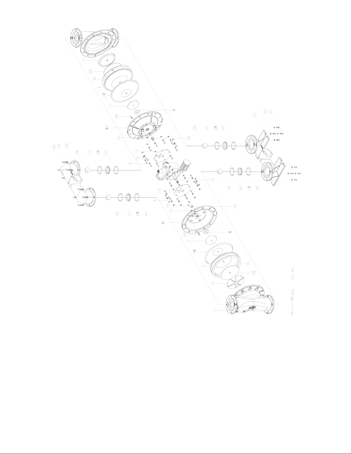
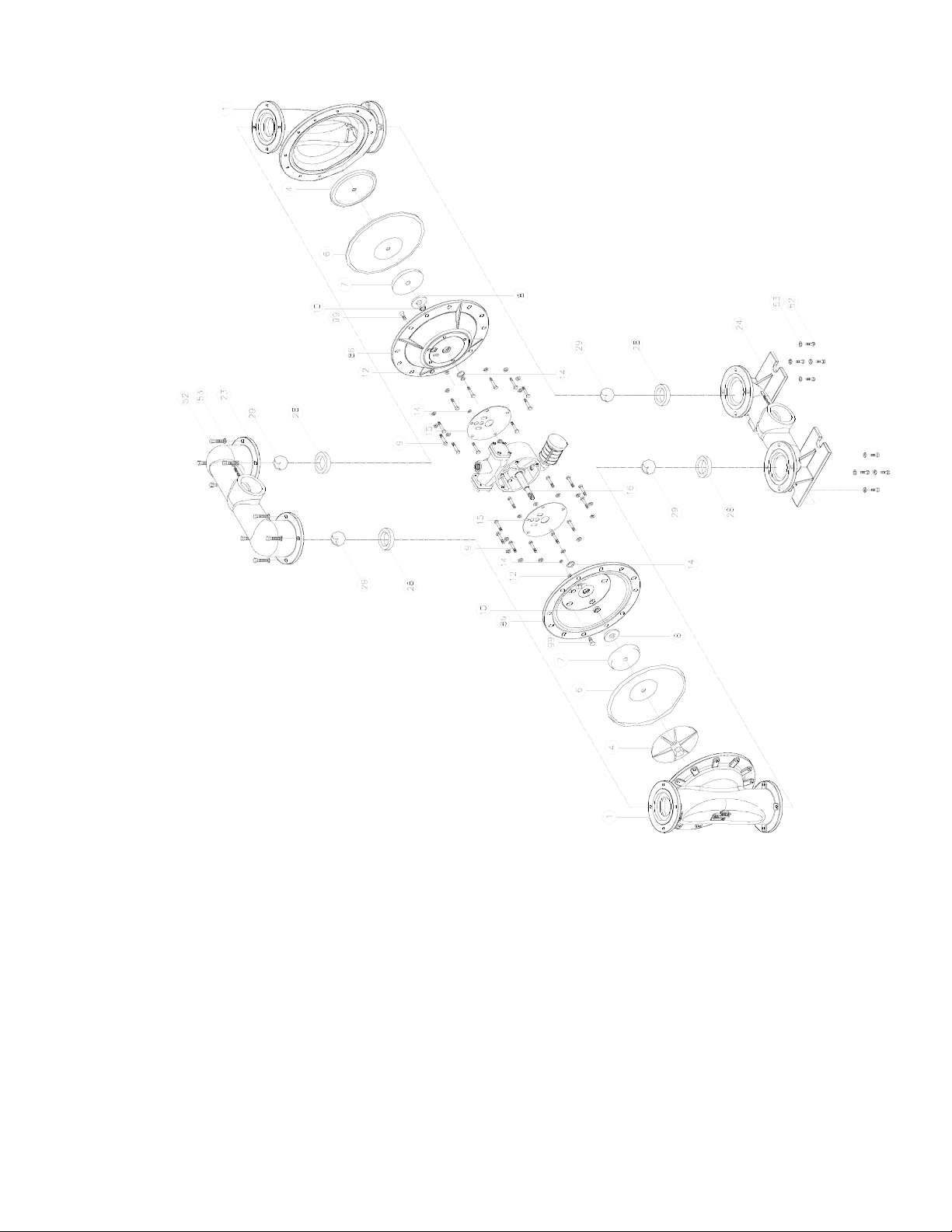
Model 3AOD-STTS-B Stainless Steel
(Teflon Elastomers)
1 Chamber, Pump
4 Plate, Diaphragm (Outer)
6 Diaphragm
7 Plate, Diaphragm (Inner)
8 Bumper
9 Cap Screw
12 + Seal
14 + Seal
15 + Gasket, Air Valve / Chamber
16 Shaft, Pump
23 Manifold, Discharge
24 Manifold, Suction
28 Seat, ball Valve
29 Ball Valve
47 O-ring
48 Back-up Diaphragm
51 Gortex Tape
52 Cap Screw
53 Lockwasher
86 Chamber, Air
91 Cap Screw
96 Flat Washer
99 Capscrew, Flat Socket Head
Page 11
IN-AOD-300M-B rev. - Page - 11
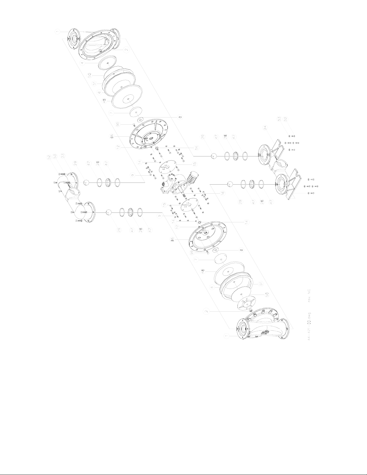
Model 3AOD-SXXX-B Stainless Steel
(All Elastomers Except Teflon)
1 Chamber, Pump
4 Plate, Diaphragm (Outer)
6 Diaphragm
7 Plate, Diaphragm (Inner)
8 Bumper
9 Cap Screw
12 + Seal
14 + Seal
15 + Gasket, Air Valve / Chamber
16 Shaft, Pump
23 Manifold, Discharge
24 Manifold, Suction
28 Seat, ball Valve
29 Ball Valve
52 Cap Screw
53 Lockwasher
86 Chamber, Air
91 Cap Screw
96 Flat Washer
99 Capscrew, Flat Socket Head
Page 12
IN-AOD-300M-B rev. -Page - 12
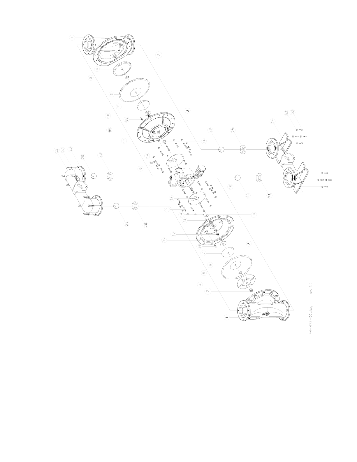
1 Chamber, Pump
2 Lock Nut
4 Plate, Diaphragm Outer)
6 Diaphragm
7 Plate, Diaphragm (Inner)
8 Bumper
9 Cap Screw
12 + Seal
14 + Seal
15 + Gasket, Air Valve / Chamber
16 Shaft, Pump
23 Manifold, Discharge
24 Manifold, Suction
28 Seat, ball Valve
29 Ball Valve
47 O-ring
51 Gortex Tape
52 Cap Screw
53 Lockwasher
86 Chamber, Air
96 Flat Washer
99 Capscrew, Flat Socket Head
Model 3AOD-ATTA-B Aluminum
(Teflon Elastomers)
Page 13
IN-AOD-300M-B rev. - Page - 13
1 Chamber, Pump
2 Lock Nut
4 Plate, Diaphragm (Outer)
6 Diaphragm
7 Plate, Diaphragm (Inner)
8 Bumper
9 Cap Screw
12 + Seal
14 + Seal
15 + Gasket, Air Valve / Chamber
16 Shaft, Pump
23 Manifold, Discharge
24 Manifold, Suction
28 Seat, ball Valve
29 Ball Valve
52 Cap Screw
53 Lockwasher
86 Chamber, Air
96 Flat Washer
99 Capscrew, Flat Socket Head
Model 3AOD-AXXX-B Aluminum
(All Elastomers Except Teflon)
Page 14
IN-AOD-300M-B rev. -Page - 14
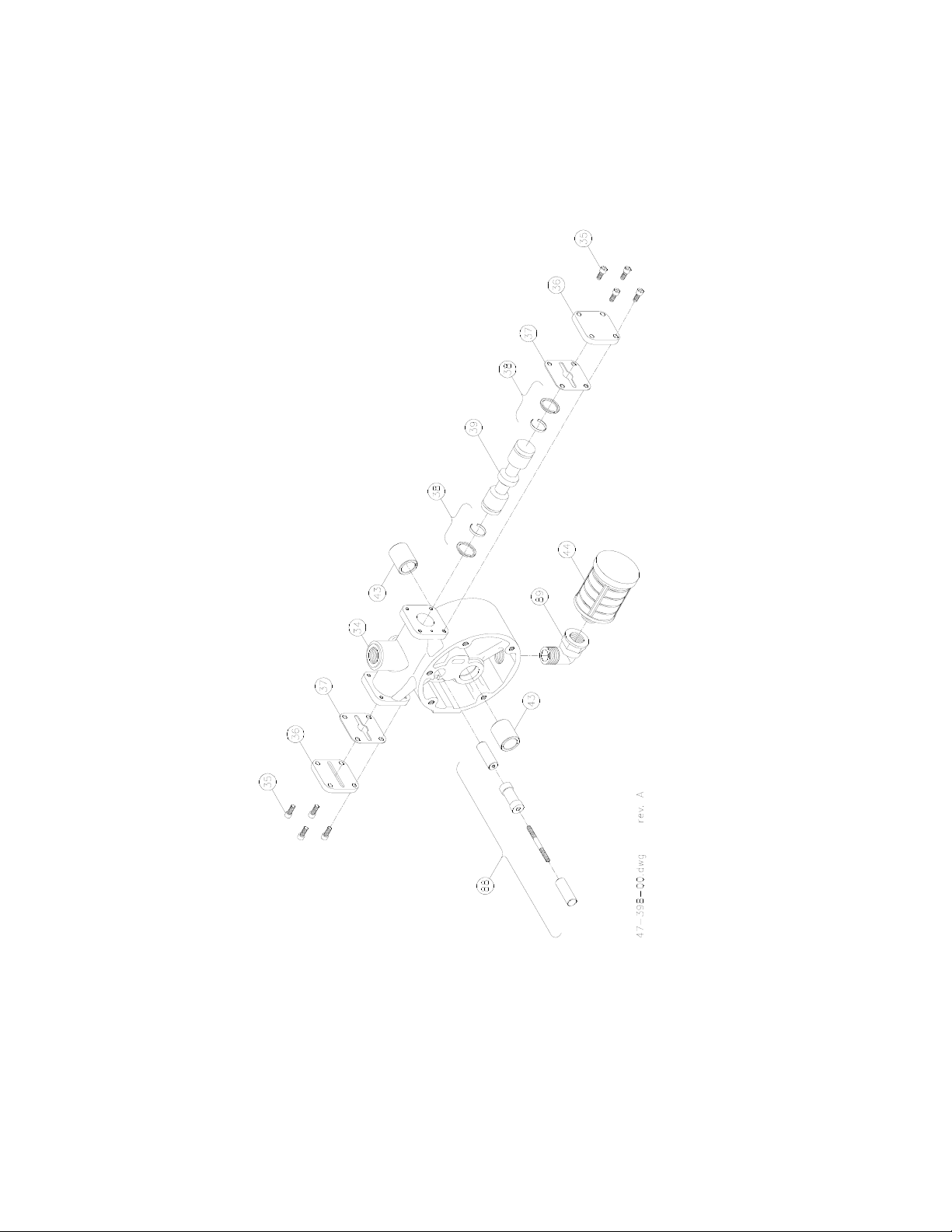
CAP, SPOOL HOUSING
SPOOL, AIR VALVE
34 HOUSING, AIR VALVE
448988
373943
38
35
36
MUFFLER
PILOT SPOOL ASSEMBLY
ELBOW
CAP SCREW, SOCKET HEAD
PISTON RING W/ EXPANDER
SLEEVE, BUSHING
GASKET, CAP
KEY DESCRIPTION
(ALL ELASTOMERS)
MODELS 2 & 3 AOD - AIR VALVE
Figure 5
Page 15
Page - 15IN-AOD-300M-B rev. -
AOD® PUMP W
ARNINGS
A Static charge buildup could occur in a plastic pump or an electrically insulated metal pump.
Any contaminants in the air supply will be exhausted out the muffler to the atmosphere.
All piping connections to the pump should be flexible.
The chemical compatibility of the pump materials of construction with the fluids being pumped must
be checked before use.
AOD®pumps are not to be used for sanitary food applications.
Submerged AOD®pumps should have their exhaust pipes away from the liquid level. A submerged
pump may leak some air from gasketed joints. Do not submerge pumps in corrosive media.
A pump which has stopped due to air valve icing will restart by itself when ice melts.
Use only original factory replacement parts.
Before start-up re-torque all external fasteners to the torque values listed in the I&O manual supplied
with the pump.
Pump temperature limits must be observed: Polypro pump - 150 deg F max. (65 deg. C)
Metal pump - 180 deg F max. (82 deg. C)
Do not exceed 125 psi (8.79 bar) air inlet pressure as component damage or personal injury may result.
AOD®pumps must only be operated by oil free, clean, dry compressed air
Shut off, bleed down and disconnect the compressed air supply before doing any maintenance or
repair to the pump.
The pump should be flushed before disassembly. The pump should be inverted (outlet at bottom) to
drain properly.
A diaphragm failure could:
a. cause the system to which the pump is connected to be pressurized up the the compressed air
supply pressure and mix air with the fluid being pumped.
b. Cause the fluid being pumped to be sprayed out through the exhaust muffler.
AOD®pumps are not suitable for use with 1,1,1-trichloroethane, methylene chloride or other
materials containing halogenated hydrocarbons. Aluminum wetted parts can react with these solvents
and explode. Consult solvent suppliers for compatibility with aluminum before installation.
For 1-1/2”,2” and 3” AOD®pumps- CAUTION- unit weight may exceed 651bs. (30 kg).
AOD
®
sound level at a distance of 1 meter with an air inet pressure of 35 psig.
Pump Size in Inches Pump Material Sound Pressure Level (RMS db)
1/2” Non-Metallic 82 db
1” Non-Metallic 82 db
1” Metallic 82 db
1-1/2” Metallic 82 db
2” Non-Metallic 79 db
2” Metallic 80 db
3” Metallic 80 db
Page 16
1. GENERAL
A. Seller's price is based on these sales terms and conditions. The agreement and inclusion of
other or amended terms in this contract will result in a change (including increase) in Seller’s
price (as may contained in any price books or quotations) to reflect such other or amended
terms. this contract shall represent the final, complete and exclusive statement of the agreement
between the parties and may not be modified, supplemented, explained or waived by parole
evidence, any Terms and Conditions contained in Buyer’s purchase order or request for
quotation, any course of dealings between parties, Seller’s performance or delivery, or in any
other way. The Terms and Conditions of this contract may only be modified or waived in a
written document signed by an Officer of Seller. These terms are intended to cover all activity
of Seller and Buyer hereunder, including sales and use of products, parts and work and all
related matters (references to products include parts and references to work include construction,
installation and start-up). Any reference by Seller to Buyer’s specifications and similar
requirements are only to describe the products and work covered hereby and no warranties or
other therms therein shall have any force of effect. Any information provided by Seller
including, but not limited to, suggestions as to specific equipment does not imply any guarantee
of specific suitability and/or material compatibility in a particular application. Catalogs,
circulars, similar pamphlets and information contained on websites of the Seller are issued for
general information purposes only and shall not be deemed to modify the provisions hereof.
B. The agreement formed hereby and the language herein shall be construed and enforced under
the Uniform Commercial Code as in effect in the State of California on the date hereof.
2. T
AXES
Any sales, use or other similar type taxes imposed on this sale or on this transaction and/or any
import or export duties or fees as may be assessed or imposed on or as a result of deliveries
under this transaction are not included in the price. Such taxes shall be billed separately to the
Buyer. Seller will accept a valid exemption certificate from the Buyer if applicable; however, if
an exemption certificate previously accepted is not recognized by the governmental taxing
authority involved and the Seller is required to pay the tax covered by such exemption
certificate. Buyer agrees to promptly reimburse Seller for the taxes paid.
3. PERFORMANCE, INSPECTION
AND ACCEPTANCE
A. Unless Seller specifically assumes installation, construction or start-up responsibility, all
products shall be finally inspected and accepted within thirty (30) days after arrival at point of
delivery. Where seller has responsibility for installation, construction or start-up all work shall
be finally inspected and accepted with thirty (30) days after completion of applicable work by
Seller. All claims whatsoever by Buyer, (including claims for shortages) except only those
provided for under the WARRANTY AND LIMITATION OF LIABILITY and PATENTS
Clauses, hereof, must be asserted in writing by Buyer within said thirty (30) day period or they
are waived. If this contract involves partial performance, all such claims must be asserted within
said thirty- (30) day period for each partial performance. There shall be no revocation of
acceptance. Rejection may be only for defects substantially impairing the value of products or
work and Buyer's remedy for lesser defects shall be those provided for under the WARRANTY
AND LIMITATION OF LIABILITY Clause.
B. Seller shall not be responsible for non-performance or for delays in performance occasioned
by any causes beyond Seller's reasonable control, including, by way of example and not
limitation, to labor difficulties, delays of vendors or carriers, fires, governmental actions, or
shortages of material, components, labor, or manufacturing facilities. Any delays so occasioned
shall affect a corresponding extension of Seller's performance dates, which are, in any event,
understood to be approximate. IN NO EVENT SHALL BUYER BE ENTITLED TO
INCIDENTALOR CONSEQUENTIAL DAMAGES FOR LATE PERFORMANCE OR FOR A
FAILURE TO PERFORM. Seller reserves the right to make partial shipments and to ship
products, parts or work which may be completed prior to scheduled performance date.
C. In the event that Seller has agreed to mount motors, turbines, gears, or other products which
are not manufactured by Seller and which are not an integral part of Seller's manufactured
product, and a delay in the delivery of such products to Seller occurs that will cause a delay in
Seller's performance date, Seller reserves the right to ship its product upon completion of
manufacture and to refund an equitable portion of the amount originally included in the purchase
price for mounting without incurring liability for non-performance.
D. Seller reserves to itself the right to change its specifications, drawings and standards if such
changes will not impair the performance of its products, and parts, and further those products,
and parts, will meet any of Buyer's specifications and other specific product requirements which
are a part of this agreement. Seller is a global supplier of products and utilizes parts and
products obtained worldwide, and Seller's products supplied under this contract shall be subject
to seller’s sole determination as to all manufacturing, sourcing, assembly and supply unless
otherwise specifically agree in writing.
E. The manufacture and inspection of products and parts shall be to Seller's Engineering and
Quality Assurance standards plus such other inspections or tests of documentation as are
specifically agreed to by Seller. Requirements for any additional inspection, tests,
documentation, or Buyer witness of manufacture, test, and/or inspection shall be subject to
additional charges.
4. TITLE
AND RISK OF LOSS
Title and risk of loss shall pass to buyer upon delivery of products at the designated "Ex Works"
as defined by Incoterms, unless other wise agreed by the parties.
5. EROSION AND CORROSION
It is specifically understood that products and parts sold hereunder are not warranted for
operation with erosive or corrosive fluids or for operation with any fluid or under any operating
condition in variance with the specifications of this contract. No product or part shall be deemed
to be defective by reason of failure to resist erosive or corrosive action of any fluid and Buyer
shall have no claim whatsoever against Seller therefore. No product shall be deemed defective
by reasons of any effect on Seller's products of the action or results (such as vibration) of any
goods or system (such as piping) not supplied by Seller.
6. BUYERS RESPONSIBILITY
The design specifications of the equipment require the operation of the equipment within certain
parameters and may call for the use of speed controls, safety devices, set points or other control
devices to insure that the operation remains within design parameters. Buyer agrees and
understands that the equipment must be operated and maintained within design specifications
and operated within the specifications of the contract, irrespective of whether controls or devices
are otherwise required.
7. W
ARRANTYAND LIMITATION OF LIABILITY
A. Seller warrants only that its product and parts, when shipped, will be free from defects in
materials and workmanship. All claims for defective products or parts under this warranty must
be made in writing immediately upon discovery and, in any event, within two (2) years of
shipment by seller and all claims for defective work must be made in writing upon discovery.
ANY UNAUTHORIZED DISASSEMBLY, ALTERATION OF OR TAMPERING WITH ANY
PRODUCT OR COMPONENT MAYVOID THE WARRANTY, IN THAT SUCH ACTION
WILL RESULT IN SELLER BEING RELEASED AND RELIEVED FROM ITS
OBLIGATIONS UNDER THIS WARRANTYAND FOR ANY FURTHER COSTS OR
CATIONS UNDER CLAUSE 7.C, FOLLOWING, AND THE BUYER ASSUMING SOLE
RESPONSIBILITY FOR THE COSTS AND RESULTS OF SUCH ACTION. THE
FOREGOING S EXPRESS, IMPLIED AND STATUTORY, INCLUDING WITHOUT
LIMITATION, THE IMPLIED, WARRANTIES OF MERCHANTABILITY AND FITNESS.
B. ANY PRODUCT (S) SOLD HEREUNDER WHICH IS NOT MANUFACTURED BY
SELLER ARE NOT WARRANTED BY SELLER and shall be covered only by the express
warranty, if any, of the manufacturer thereof. With respect to products and parts not
manufactured by Seller, Seller’s only obligation shall be to assign to Buyer, to the extent
possible, whatever warranty Seller obtains from the manufacturer.
C. Upon Buyer's submission of a claim as provided above and its substantiation, Seller shall at
its option either (i) repair or replace its product, part or work at the original place of shipment, or
(ii) refund an equitable portion of the purchase price.
D. THE FOREGOING IS SELLER'S ONLY OBLIGATION AND BUYER'S EXCLUSIVE
REMEDY FOR BREACH OF WARRANTYAND, EXCEPT FOR BREACH OF WARRANTY
AND, EXCEPT FOR THE REMEDIES PERMITTED UNDER THE PERFORMANCE,
INSPECTION AND ACCEPTANCE AND THE PATENTS CLAUSES HEREOF, THE
FOREGOING IS BUYER EXCLUSIVE REMEDY AGAINST SELLER FOR ALL CLAIMS
ARISING HEREUNDER OR RELATING HERETO WHETHER SUCH CLAIMS ARE
BASED ON BREACH OF CONTRACT, TORT (INCLUDING NEGLIGENCE OR STRICT
LIABILITY), INDEMNITY OR OTHER THEORIES. BUYER’S FAILURE TO SUBMIT A
CLAIM AS PROVIDED ABOVE SHALLSPECIFICALL YWAIVE ALL CLAIMS FOR
DAMAGES OR OTHER RELIEF, INCLUDING BUTNOT LIMITED TO CLAIMS BASED
ON LATENT DEFECTS. IN NO EVENT SHALL BUYER BE ENTITLED TO INDIRECT,
SPECIAL, INCIDENTALOR CONSEQUENTIAL DAMAGES, NOR FOR DAMAGES FOR
LOSS OF USE, LOST PROFITS OR REVENUE, INTEREST, LOST GOODWILL, WORK OR
PRODUCTION STOPPAGE, IMPAIRMENT OF OTHER GOODS, INCREASED EXPENSES
OF OPERATION, OR THE COST OF PURCHASING REPLACEMENT POWER OR OTHER
SERVICES BECAUSE OR SERVICE INTERRUPTIONS. FURTHERMORE, IN NO EVENT
SHALL SELLER’S TOTALLIABILITY FOR DAMAGES OF BUYER EXCEED THE
PURCHASE PRICE OF THE PRODUCTS OR PARTS MANUFACTURED BYSELLER AND
UPON WHICH SUCH LIABILITY IS BASED. ANYACTION (INCLUDING NEGLIGENCE)
OR OTHER THEORIES, MUST BE COMMENCED WITHIN ONE (1) YEAR AFTER THE
CAUSE OF ACTION ACCRUES OR IT SHALL BE BARRED.
8. PURCHASER'S REPRESENT
ATIONS & WARRANTIES
Purchaser represents and warranties that the products(s) covered by this contract shall not be
used in or in connection with a nuclear facility or application. The parties agree that this
representation and warranty is material and is being relied on by seller. This provision may be
modified in a separate writing signed by an officer of Price Pump Co.
9. P
ATENTS
Seller agrees to assume the defense of any suit for infringement of any patents brought against
Buyer to the extent of such suit charges infringement of an apparatus or product claim by
Seller's product in and of itself, provided (i) said product is built entirely to Seller's design, (ii)
Buyer notifies Seller in writing of the filing of such suit within ten (10) days after the service of
process thereof, and (iii) Seller is given complete control of the defense of such suit, including
the right to defend, settle and make changes in the product for the purpose of avoiding
infringement of any process or method claims. Provided however, Seller will not defend any
suit for infringement of a claimed patent where such alleged infringement is the result of
following specific instruction furnished by Seller.
10. EXTENT
OF SUPPLY
Only products as listed in Seller's proposal are included in this agreement. It must not be
assumed that Seller has included anything beyond same.
11. MANUF
ACTURING SOURCES
To maintain delivery schedules, Seller reserves the right to have all or any part of the Buyer's
order manufactured at any of Sellers', sellers' licensees or sub contractors' plants, globally.
12. TERMS OF
PAYMENT
Net 30 days from date of invoice.
13. ARBITRATION
In the event a dispute arises between the parties relating to or arising out of this agreement, the
parties agree to attempt to have their senior management amicably settle the matter. In the event
that the matter cannot be settled, the parties shall submit all disputes relating to this Agreement
(whether contract, tort, products liability or otherwise) to binding Arbitration before a panel of
arbitrators under the Commercial Dispute Resolution Procedures of the American Arbitration
Association. Each party shall appoint an arbitrator and the third shall be selected in accordance
with the rules of the American Arbitration Association. Judgment upon the award may be
entered in any court having jurisdiction. The parties shall cooperate in providing reasonable
disclosure of relevant documents. Each party shall bear its own expenses, and the costs and fees
of the arbitration shall be borne as allocated by the Arbitrator.
GENERAL TERMS OF SALE FOR PRODUCTS
IN-AOD-300M-B rev. -
 Loading...