

Priceless Aviation Products 747B, 747C Technical Manual And Parts List

Technical Manual & Parts Lists
Revision 1
May 09, 2106


Technical Manual & Parts Lists
1
IMPORTANT
It is important to read and understand the information contained within
this manual before attempting to operate the machine. Priceless
Aviation Products shall not be held liable for damage resulting from
misuse of the information presented within, and reserves the right to
change the information contained within, without prior notification.
Priceless Aviation Products
Confidential and Proprietary Information
The materials contained herein are confidential and proprietary information of Priceless Aviation
Products. In addition to any confidentiality and non-disclosure obligations that currently exist between
you and Priceless Aviation Products, your use of these materials serves as an acknowledgment of the
confidential and proprietary nature of these materials and your duty not to make any unauthorized use or
disclosure of these materials.
All materials contained herein are additionally protected by United States Copyright law and
may not be used, disclosed, reproduced, distributed, published or sold without the express written
consent of Priceless Aviation Products, which consent may be withheld in Priceless Aviation Products’
sole discretion. You may not alter or remove any copyright, trademark or other notice from copies of
these materials.
COPYRIGHT© 2015 Priceless Aviation Products, LLC. All rights reserved.
Priceless Aviation Products, LLC
362 Industrial Park Drive
Lawrenceville, Georgia 30046
USA: (770) 962-6188
Toll Free: (877) 206-5116
Fax: (770) 277-4141
Europe Tel +44 (0) 1794 518888
Fax +44 (0) 1794 518848

Technical Manual & Parts Lists
2
Contents
General Information .................................................................................................................................... 1
Delivery....................................................................................................................................................... 2
Parts and Service ......................................................................................................................................... 2
Office Hours................................................................................................................................................ 2
Safety Precautions ....................................................................................................................................... 3
Installation................................................................................................................................................... 5
Technical Data ............................................................................................................................................ 6
Specifications .............................................................................................................................................. 6
Dimensions ................................................................................................................................................. 6
Options ........................................................................................................................................................ 6
Component Identification ........................................................................................................................... 7
Operating the Tug ....................................................................................................................................... 8
Starting the Engine ...................................................................................................................................... 8
Driving the Tug ........................................................................................................................................... 9
Steering the Tug .......................................................................................................................................... 9
Loading the Nose Gear ............................................................................................................................. 10
Maintenance .............................................................................................................................................. 11
Maintenance Schedule .............................................................................................................................. 12
Torque Values ........................................................................................................................................... 12
Tire Specifications .................................................................................................................................... 13
Electric System ......................................................................................................................................... 13
Fuel System ............................................................................................................................................... 13
Hydraulic Systems .................................................................................................................................... 14
Engine Oil & Filter ................................................................................................................................... 15
General Engine Maintenance .................................................................................................................... 15
V-Belt Maintenance .................................................................................................................................. 15
Checking brakes ........................................................................................................................................ 16
Adjusting the brakes ................................................................................................................................. 16
Storage ...................................................................................................................................................... 16
Preparing the Engine for Storage .............................................................................................................. 16
Operating the Tug after Storage ................................................................................................................ 17
Assembly Drawings & Parts Lists ............................................................................................................ 18
747C AIRCRAFT TUG, HD CRADLE ................................................................................................... 22
747C AIRCRAFT TUG, HD CRADLE (CONT’D) ................................................................................ 23
1000191 Plane Mover Arm Assembly ...................................................................................................... 24
1000135 HYDRAULIC CYLINDER, 3” BORE ..................................................................................... 25

Technical Manual & Parts Lists
3
................................................................................................................................................................... 26
1002599 ARM ASSEMBLY, 4” LONGER ............................................................................................. 26
1002778 TURNING WHEEL ASSEMBLY ............................................................................................ 27
1003044 HYD TANK ASSEMBLY ........................................................................................................ 28
1003104 SCOOP 747B PLANE MOVER ................................................................................................ 29
1003360 STEERING/CONTROL MAST ................................................................................................ 31
10003296 MOTOR-PUMP ASSEMBLY, CONT. USE .......................................................................... 33
757FBO-WD WIRING DIAGRAM UNIVERSAL ................................................................................. 34

Technical Manual & Parts Lists
1
IMPORTANT
The engine owner’s manual is included with your owner’s packet which
contains additional information that will not be repeated in this manual.
You are urged to refer to the engine owner’s manual before attempting
any operation or repair of the unit.
General Information
This manual applies to Priceless Aviation Products Model No. 747B.
To The New Owner
The purpose of this manual is to assist owners and operators in maintaining and operating the
747B. Please read it carefully; information and instructions furnished can help you achieve years of
dependable performance.
It is the owner’s responsibility to make certain the operator reads and understands this manual
before operating this machine. It is also the owner’s responsibility to make certain that the operator is a
qualified and physically able individual, properly trained in the operation of this equipment.
Using This Manual
General operation, adjustment and maintenance guidance is outlined for both the experienced
and novice user. Operating conditions vary considerably and cannot all be addressed individually.
Through experience, however, operators should find no difficulty in developing good operating skills
suitable to most conditions.
Directions used in this manual, for example RIGHT or LEFT, refer to directions when standing
in front of handle bar facing forward, unless otherwise stated.
Photographs and illustrations used were current at the time of printing, but subsequent
production changes may cause your machine to vary slightly in detail. Priceless Aviation Products
reserves the right to redesign and change the machine as deemed necessary, without notification. If a
change has been made to your machine which is not reflected in this owner’s manual, or the parts
manual, contact Priceless Aviation Products for current information and parts.

Technical Manual & Parts Lists
2
Delivery
Check for damage upon delivery of the machine. Contact the delivery carrier and Priceless
Aviation Products immediately, if damage is noticed. Keep all shipping papers for Priceless Aviation
Products Service Representative.
Perform the following steps before starting the tug.
STEPS
1) Clean unit, removing dirt and debris accumulation.
2) Check the engine oil level. Refer to the Briggs & Straton Engine Manual.
3) Check the hydraulic oil levels.
4) Tighten any bolts that may have loosened and make sure all hair pins, cotter pins and clevis pins
are in place.
5) Install all safety shields and review safety precautions listed in this manual.
6) Fill the gas tank with fresh gasoline. Run the tug at half speed for 5 minutes, checking operation
of the steering, braking, scoop lift, and other functions.
7) Shut engine off and check for any fluid leaks and/or loose fittings. Adjust and tighten bolts
and/or fittings if necessary.
Parts and Service
Use Priceless Aviation Products replacement parts only. To obtain prompt, efficient service,
always provide the following information when ordering parts or requesting technical service:
Correct part number and description, as listed in the assembly drawings located in the back of
this manual.
Correct model number.
Correct serial number.
Parts orders placed before 12:00 pm (EST) will ship the same day, if the items are in stock.
Office Hours
Monday - Friday: 7:00 am - 5:00 pm (EST)
Contact Information
Priceless Aviation Products, LLC
362 Industrial Park Drive
Lawrenceville, Georgia 30046
USA: (770) 962-6188
Toll Free: (877) 206-5116
Fax: (770) 277-4141
Europe Tel +44 (0) 1794 518888
Fax +44 (0) 1794 518848
www.pricelessaviation.com

Technical Manual & Parts Lists
3
DANGER
DANGER statements refer to immediate hazards or unsafe practices which WILL
result in severe personal injury or death; including extensive equipment or
property damage.
WARNING
WARNING statements refer to hazards or unsafe practices which COULD result in
severe personal injury or death; including major equipment or property damage.
CAUTION
CAUTION statements refer to hazards or unsafe practices which COULD result in
minor personal injury; or damage to the equipment or property.
IMPORTANT
IMPORTANT statements refer to special instructions to avoid unnecessary steps,
avoid damage to parts, or to make a procedure easier. These statements are NOT
USUALLY safety related.
Safety Precautions
Throughout this manual, safety related information is displayed with a signal word. The signal word
designates the level of hazard. The following examples explain the level of hazard connected with each
signal word.

Technical Manual & Parts Lists
4
IMPORTANT
EVERYONE involved with the operation and maintenance of this
should read and follow the instructions in this manual.
Operate the equipment only as stated in this manual. Incorrect use
cause damage to the equipment or personal injury.
It is the owner’s responsibility to make certain that the operator reads
understands this manual before operating this equipment. It is also
owner’s responsibility to make certain that the operator is a qualified
physically able individual, properly trained in the operation of
equipment.
Safety should be a constant concern for EVERYONE. ALWAYS be careful when working with
this equipment. While normal safety precautions were taken in the design and manufacture of this
equipment, there are some potential safety hazards.
Specific safety warning decals are located on the equipment near the immediate areas of potential
hazards. These decals should not be removed or obliterated. Replace them if they become non-readable.
ALWAYS keep safety shields and covers in place, except for servicing.
ALWAYS maintain a safe distance from people when operating.
ALWAYS operate equipment in daylight or with adequate working lights. Follow daily and
weekly checklists, making sure hoses are tightly secured and bolts are tightened.
ALWAYS watch and avoid holes or deep depressions.
ALWAYS wear adequate eye protection when servicing the hydraulic system and battery.
NEVER operate a poorly maintained machine.
NEVER attempt high speed maneuvering, especially in crowded or congested areas.
NEVER allow persons to operate this machine without proper instruction.
NEVER put hands or feet under any part of the machine while it is running.
NEVER leave machine unattended with ignition key in switch.
NEVER refuel unit while engine is running; NEVER refuel near an open flame or near devices
which can create a spark. Refuel outdoors preferably, or in well ventilated areas.
NEVER attempt to start engine when there is a strong odor of gasoline fumes present. Locate
and correct cause.
NEVER run the engine in an enclosed area unless exhaust is vented to the outside. Exhaust gases
contain carbon monoxide which is odorless and deadly poison.
NEVER attempt to make any adjustments or repairs to the machine while the tug engine is
running. Repairs or maintenance requiring engine power should be performed by trained
personnel only.
NEVER work under the machine unless it is safely supported with stands, blocks or a hoist and
blocks.
Do not touch hot parts of machine.
Do not operate where the machine could slip or tip.
Wet terrain can dramatically affect traction. Extreme caution should be observed to avoid loss of
control due to the inability to stop.

5
Installation
Installing the Rider Platform
Refer to Figure 1.
1) Manually activate and lock wheel brakes.
2) Position wheel chocks against both sides of the tires. Make sure they are snug and in the center
of the tire.
3) Insert the mounting tubes of the Rider Platform (1) into the receiver tubes of the main tug
assembly. Line up the holes and lock into place using the bolts and washers (2) provided.
Technical Manual & Parts Lists
4) Install the Push/Pull control cables to the cable bracket.
5) Adjust the stop switch limit bolts until the cable’s rod ends align with the tapped holes in the
cable brackets.
6) Bolt the cables rod ends into the bracket.
7) Adjust the stop switch limit bolts again to allow proper stroke of the gas springs.
Technical Manual & Parts Lists
6
Technical Data
Specifications
23hp Briggs & Straton Engine
Steering wheel for easy turning.
Hydraulic wheel motor drive
Electric winch & quick-lock strap.
Super-duty solid traction tires.
Automatic parking brake.
Heavy-duty alternator.
Battery charging system
Electric key start.
No-skid riding platform surface.
Electro-hydraulic nose wheel pan.
Headlight
Capable of moving aircraft weighing up to 25,000 lbs.
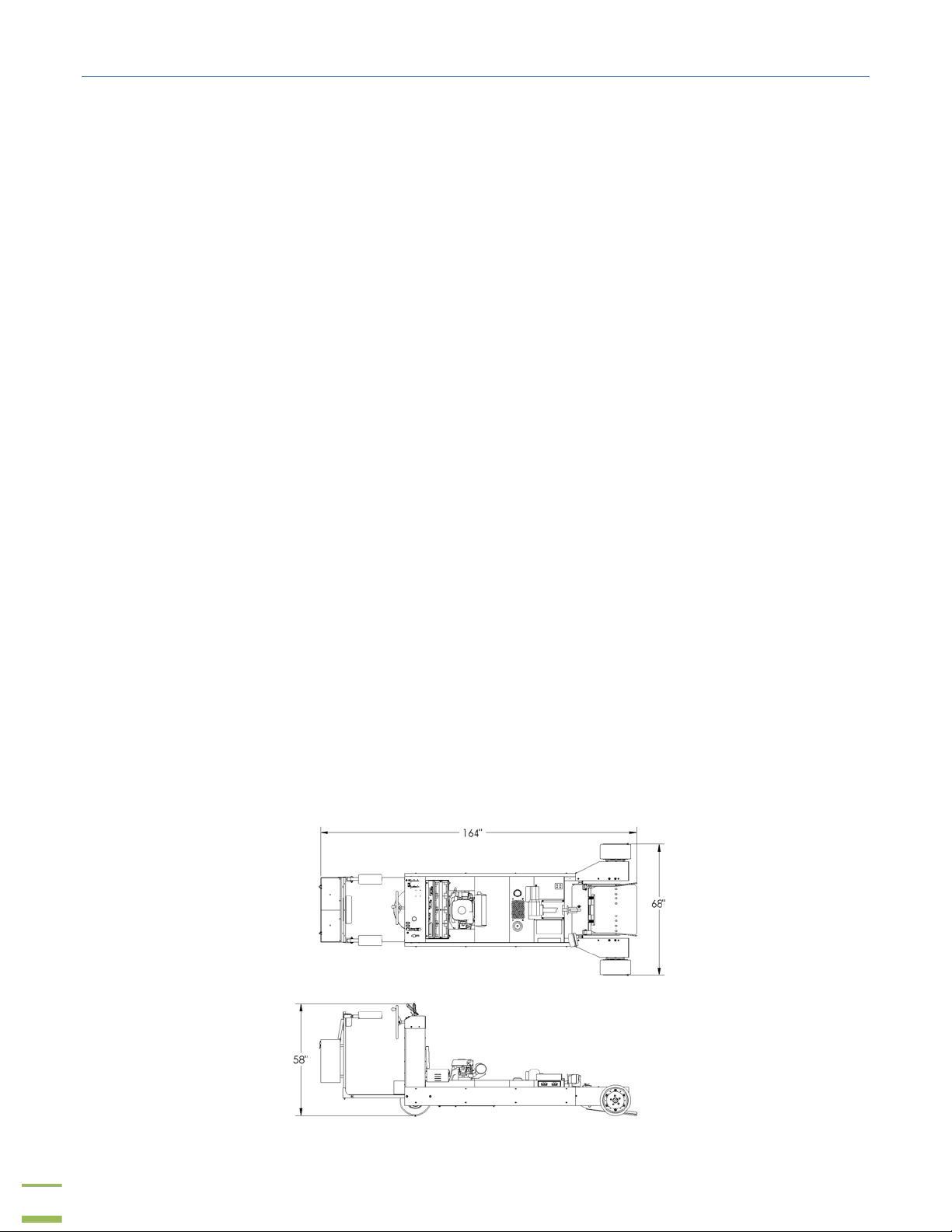
Dimensions
Approx. 156” x 69” x 59”
Options
Forward/Reverse alarm
Cirrus Attachment
Amber Strobe Light
Pintle Hitch
2nd Headlight
Dual drive wheels
Fire Extinguisher

7
Component Identification
Figure 5
Refer to Figure 5.
1. Steering Wheel 12. Nose Gear Arm
2. Rider Platform 13. Wheel Scoop
3.Engine Hours Counter 14. Forward/Reverse Lever
4. Gas Tank 15. Throttle
5. Oil Filter 16. Light Switch
17. Winch In/Out Switch
7. Headlight 18. Scoop Lift Switch
8. Air Filter 19. Ignition Switch
9. Oil Reservoir / Gauge 20. Choke
10. Secondary Winch Controls 21. Parking Brake
11. Winch
Technical Manual & Parts Lists

Technical Manual & Parts Lists
8
DANGER
Prior to operating the tug the operator should be thoroughly familiar
with the proper use and operation of the equipment, should read the
manual completely and thoroughly, and should have attempted slow
moving maneuvers to become familiar with the operation of the
equipment before attempting normal speed operation.
Operating the Tug
It is important that the operator read this manual and become familiar with all of the functions and safety
concerns of this unit before operating.
Slow moving, practice maneuvers are recommended to become familiar with the speed controls
and steering methods before attempting normal speed, aircraft towing operation.
Starting the Engine
1) Pull the choke all the way open.
2) Set the throttle to half way.
3) Turn the key in the On/Off switch to the Start position and hold it there while pushing the choke
down.
4) Once the engine is started, return the key to the On position.
5) Set the desired throttle adjustment.
 Loading...