

Price UMC3 Series Manual
MANUAL – INSTALLATION + SERVICE
Underfloor ModuFlex Controller
UMC3 Series
v100 – Issue Date: 09/20/17
© 2017 Price Industries Limited. All rights reserved.

UNDERFLOOR MODUFLEX CONTROLLER
TABLE OF CONTENTS
Product Overview
Introduction ................................................................... 1
General Safety Guidelines..............................................1
Safety Precautions .......................................................1
Safety Symbols ............................................................. 1
Underfloor Systems Control Zones ................................ 2
General Description ....................................................... 3
Features of the UMC3 ................................................... 4
Operation ...................................................................... 4
Installation & Mounting Instructions
Installation ..................................................................... 5
Price Flow Response Chart ........................................... 5
Input/Output Description ............................................... 6
Wiring ........................................................................... 7
Thermostat Installation .................................................. 8
How to use Thermostats ............................................... 9
Display Navigation
Initial Startup ............................................................... 10
Service Menu .............................................................. 11
Balancing Menu .......................................................... 12
VVT Menu ................................................................... 13
Setpoint Menu ............................................................. 14
Input Menu .................................................................. 15
Output Menu - Aux Binary ........................................... 16
Output Menu - Analog Outputs ................................... 17
Stat Setup Menu ......................................................... 18
Info Menu .................................................................... 19
Address Menu ............................................................. 20
Networking & Setup
BACnet Networking and Setup ................................... 21
Setting the Device Instance ......................................... 22
LINKER - USB Service Tool ......................................... 23
Maintenance
Troubleshooting ........................................................... 24
Hardware Specifications .............................................. 25
UNDERFLOOR MODUFLEX CONTROLLER
PRODUCT OVERVIEW
Introduction
In this manual, you will find technical descriptions and
diagrams of underfloor system components along with
their installation instructions. Practical guidelines and
recommendations are also provided. If more information is
required about this equipment, please contact a Price sales
representative.
General Safety Guidelines
This document is intended for use by owner-authorized
operating/service personnel who are expected to possess the
required training to enable them to perform their tasks properly
and safely. This individual must have read and understood this
document and any referenced materials prior to performing any
task on this equipment. Also, it is essential that this individual
be familiar with and comply with all applicable governmental
standards and regulations pertaining to the task in question.
This individual must also verify that installation and connections
comply with local building codes. It is the obligation and
responsibility of the operating/service personnel to identify and
recognize these inherent hazards, protect themselves, and
proceed safely in completing their tasks. Failure to comply
with any of these requirements could result in severe personal
injury or death to themselves and people at the site, as well as
serious damage to the equipment and the property in which it
is situated.
The equipment discussed in this manual is relatively
complicated apparatus and must be handled with the
necessary precautions. Individuals may be exposed to certain
components or conditions such as refrigerants, oils, materials
under pressure, rotating components, and both high and low
voltage during installation, operation, maintenance or service
of this equipment. If misued or mishandled, each item has the
potential to cause bodily injury or death.
Safety Precautions
When using electrical appliances, basic safety precautions
should always be followed including the following:
1. Read all instructions.
2. Do not touch hot surfaces.
3. To protect against electrical shock do not immerse cord,
plugs, or Control Box in water or other liquids.
4. Unplug the unit when not in use and before cleaning.
5. Do not operate any appliance with a damaged cord or
plug or after the appliance malfunctions or has been
damaged in any manner. Return appliance to the nearest
authorized service facility for examination, repair or
adjustment.
6. The use of accessory attachments not recommended by
the appliance manufacturer may cause injuries.
7. Do not use outdoors.
8. Do not let cord hang over edge of a table or counter, or
touch hot surfaces.
9. Do not place on or near a hot gas or electric burner, or in a
heated oven.
10. Always attach plug to appliance first, then plug into the
power source. To disconnect, turn any control to “off”,
then remove plug from power source.
11. Do not use appliance for other than intended use.
12. Save these instructions.
Safety Symbols
The following symbols are used in this document to alert the
reader to areas of potential hazard:
WARNING
Failure to observe may result in personal injury, death or
equipment damage.
CAUTION
Failure to observe may result in equipment damage.
NOTE: Used to highlight additional information helpful to the reader.
priceindustries.com | UNDERFLOOR MODUFLEX CONTROLLER - Manual
1
UNDERFLOOR MODUFLEX CONTROLLER
Product overview
Underfloor Systems Control Zones
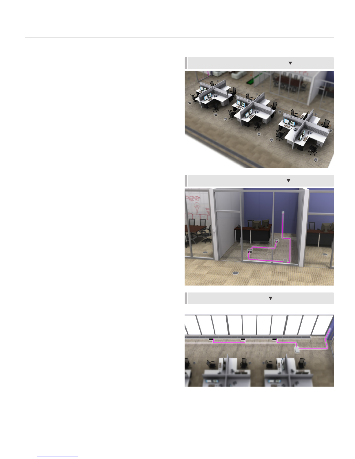
INTERIOR ZONES
Constant Air Volume - Cooling Only
Typically, interior zones have relatively stable loads hence
constant volume supply is often employed. A typical interior
zone consists of contant volume or constant pressure turbulent
floor twist outlets installed in a large, common plenum space.
In this method the entire plenum space is treated as one zone
and, under fluctuating loads, the amount of air delivered to
the space is regulated by the relative pressure in this plenum,
modulated by a single point of control. Manual face-adjustable
diffusers (MFD) provide occupant control of airflow volume.
Variable Air Volume - Cooling Only
In the case an open plenum is desired to be divided into
several zones, variable air volume control is possible with the
use of devices installed under the diffuser or with the use of a
variable volume basket. The variable volume diffusers would
be controlled by the UMC. The UMC would open and close
the diffusers releasing air from the pressurized plenum. The
variable volume (VAV) diffusers require a 24 VAC signal which is
provided by the UMC to modulate the actuators. Meanwhile,
the UMC accepts a 0 to 10 VDC cooling signal either from
a manual control signal or from a thermostat. The UMC
modulates the airflow from 0% to 100%.
CONSTANT AIR VOLUME - COOLING ONLY
VARIABLE AIR VOLUME - COOLING ONLY
PERIMETER ZONE
Trough Heating and Cooling
Use of linear floor grilles with integrated heating elements offer
a system with heightened flexibility and efficiency as it omits
the use of fan terminal units and ducting. In cooling mode,
dampers on the LFGH modulate open to the plenum allowing
more airflow into the space to satisfy the cooling demand.
When a call for heat arises, the hot water or electric coil
energizes and the diffusers either open to the plenum or to a
perimeter cavity to allow air to pass over the heating element.
LFGHs are controlled by the UMC3 where up to 12 LFGHs can
be daisy chained.
TROUGH HEATING AND COOLING
2
UNDERFLOOR MODUFLEX CONTROLLER - Manual | priceindustries.com
UNDERFLOOR MODUFLEX CONTROLLER
PRODUCT OVERVIEW
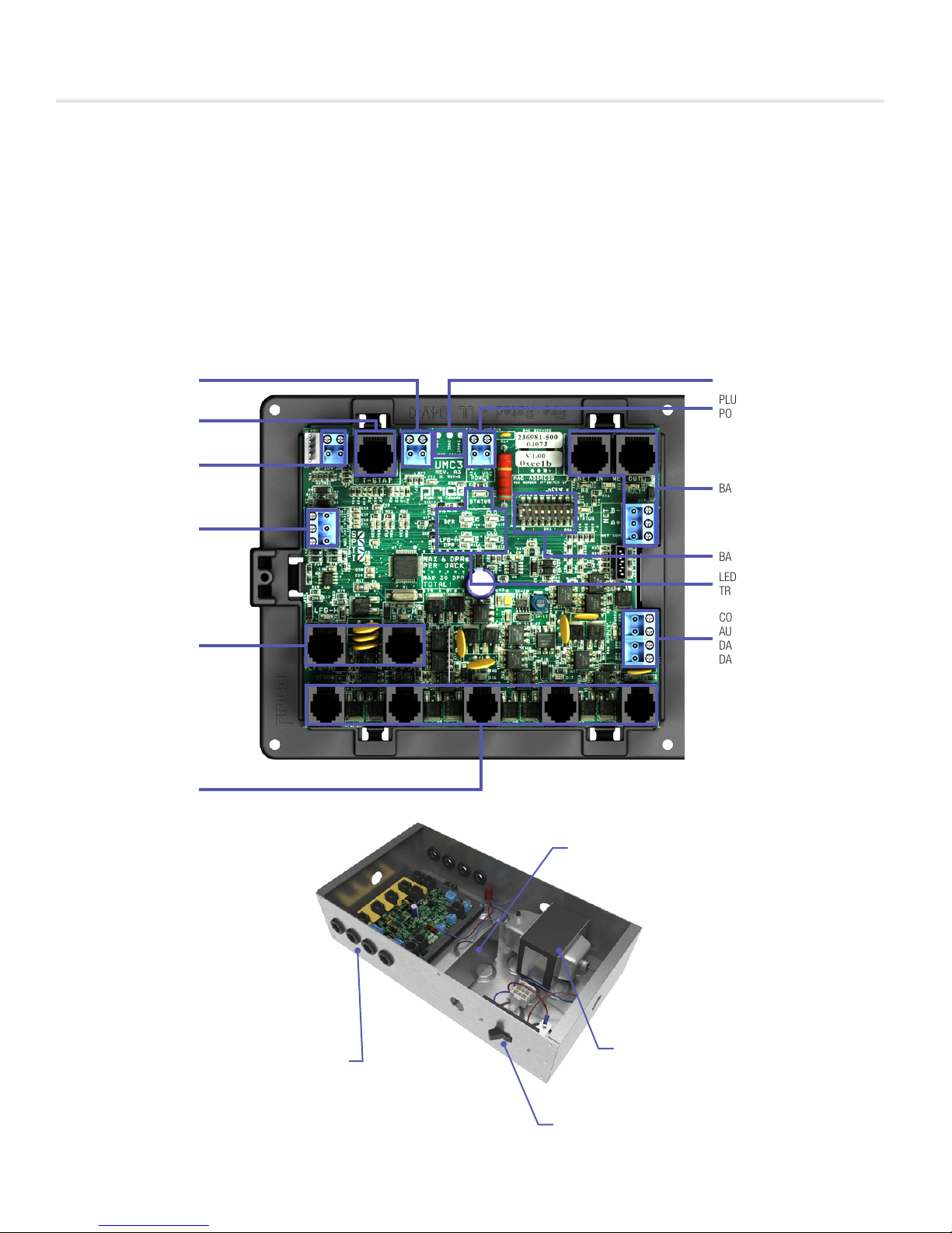
General Description
The Third Generation Underfloor ModuFlex Controller (UMC3) is a direct digital controller for pressurized underfloor plenum cooling
zones. It can control up to 30 underfloor damper/diffusers – 12 of which can be the LFGH with integrated reheat. Auxiliary inputs
and outputs add to the UMC3’s flexibility.
The UMC3 offers cutting edge zone control by combining the accuracy of direct digital control with the flexibility of an individual
zone control system; providing maximum control and efficiency. An advanced and configurable proportional integral controller
allows for exceptional user comfort and energy efficiency. Installation of the controller and thermostat is simple and error proof with
RJ-45 (network type) connections to the thermostat and BACnet network.
The UMC3 comes factory mounted in a rugged galvanized enclosure complete with a 96VA transformer and disconnect switch.
THERMISTOR INPUT
(MONITORING ONLY)
RJ-45 T-STAT PORT FOR
THERMOSTAT CONNECTION
ANALOG INPUTS
PIN 1 – COOLING
PIN 2 – HEATING
ANALOG OUTPUTS
HEAT
AUX
COM
LFGH OUTPUTS
CONNECT UP TO 6 LFGH UNITS
PER JACK FOR A TOTAL OF 12
LFGH UNITS
MODULAR DAMPER OUTPUTS
CONNECT UP TO 6 UNDERFLOOR
DAMPERS/DIFFUSERS PER JACK
FOR A TOTAL OF 30 DAMPERS/
DIFFUSERS (INCLUDING LFGH)
VOLTAGE TEST POINTS
PLUGGABLE 24VAC
POWER TERMINAL
BACNET MS/TP CONNECTIONS
BACNET MAC ADDRESS
LED INDICATORS FOR
TROUBLESHOOTING
COMMON BINARY OUTPUTS
AUX
DAMPER CLOSED
DAMPER OPEN
METAL SAFETY GUARD
SEPARATING HIGH AND
LOW VOLTAGE AREAS
OPENINGS FOR MODULAR
8 GROMMETED
CABLE CONNECTIONS
96 VA MULTI-TAP
TRANSFORMER WITH
CIRCUIT BREAKER
DISCONNECT SWITCH
priceindustries.com | UNDERFLOOR MODUFLEX CONTROLLER - Manual
3

UNDERFLOOR MODUFLEX CONTROLLER
Product overview
Features of the UMC3
• Control up to 30 underfloor dampers.
• Modular connections to dampers – Use RJ-12 cables
included with dampers to connect underfloor dampers to
UMC3. LFGH dampers use RJ-45 connections.
• Outputs protected by self-resetting thermal fuses – Prevents
damage to circuit board in the event of a damaged cable.
Fault LED lights when dampers are trying to drive on an
output with damaged cable.
• Auxiliary 24VAC Binary Output – Use for reheat, room lights,
signal to other equipment, etc. Rated for a maximum output
of 0.5A (12VA).
• Auxilary Analog Outputs (2) – Use to connect to other
equipment, BAS, etc. Output range fully configurable (210VDC, 0-10VDC, 10-2VDC, etc.). Rated at a maximum
output of 10mA each.
• Analog Inputs (2) – Configurable to allow control of the
UMC3 from a source other than a Price Thermostat (BAS,
third party thermostat, etc.). Accepts the standard dual
0-10VDC signal for cooling/heating. (if not using LFGH or
other heaters connected to UMC3, only the 0-10V cooling
signal is needed).
• Input (1) 10K type J thermistor – Can be used to monitor a
temperature over the network. Can also be used for heat/
cool changeover.
• Thermostat port - For RJ-45 connection to thermostat from
the UMC3 controller.
• Native BACnet MS/TP communication – Connect using RJ45 cable, or use discrete twisted-pair wire to terminal block.
Available speeds: 9600, 19200, 38400, 76800 (default).
• LED Indication – For ease of troubleshooting – displays
status, damper directions, BACnet status, and output fault.
• Pluggable terminal blocks – For easy installation.
• High-Voltage disconnect switch.
• 96 VA multi-tap transformer with circuit breaker.
• Metal safety guard separating high and low voltage areas.
• 8 grommeted openings for modular cable connections.
• Temperature sensor input (for monitoring).
• Disconnect switch.
• Pluggable 24VAC power terminal.
Operation
The UMC3 controller is an advanced and fully configurable
underfloor ModuFlex cooling controller. It is typically interfaced
with one of four Price Thermostats to determine room load and
allow for setup functions. With a variety of output configurations,
the UMC3 can control up to 30 underfloor dampers, as well as
auxiliary equipment using its auxiliary 24VAC binary outputs, and
analog 0-10V outputs.
Upon an increase in space temperature the controller regulates the
dampers open to increase the flow of cool air. On an increase
of space temperature greater than the proportional band,
the dampers’ positions are maintained at their pre-selected
maximum setting.
On a decrease in space temperature the controller regulates the
dampers closed to decrease the flow of cool air. If connected to
LFGH floor grills with integrated damper and reheat, the UMC3
will energize or modulate the heat proportionally to the room
demand. If the space temperature decreases to less than the
proportional band, the dampers’ positions are maintained at
their pre-selected minimum setting.
The UMC3 can also be configured to accept 0-10V input signals
from a BAS system or third party thermostat for room load
calculations, instead of data from the thermostat.
The UMC3 can be used as a stand alone unit, or can be
interfaced into a BAS with the MS/TP BACnet network.
The UMC3 offers four thermostat options that provide a range
of control from room temperature sensing, all the way to motion
sensing. With the use of the LCD Thermostat, balancing and
system setup can be achieved. Further, with the use of the LCD
Thermostat with Motion, the UMC3 can be used as a motionoccupied zone and lighting controller. The LCD Thermostat with
Motion offers different levels of sensitivity and still performs all
the functions of the regular LCD Thermostat.
4
UNDERFLOOR MODUFLEX CONTROLLER - Manual | priceindustries.com

UNDERFLOOR MODUFLEX CONTROLLER
INSTALLATION & MOUNTING INSTRUCTIONS
Installation
1. Place the UMC3 in the underfloor plenum in the center of
the controlled zone using a 35 ft. cable.
2. Supply power and ground to terminal per wiring diagram.
NOTE: This task must be completed by a certified and
licensed electrician.
3. Connect underfloor dampers using modular cables
supplied with dampers. Follow these general rules:
A. Connect no more than 30 dampers total
B. Daisy chain up to 6 dampers per output – no more
C. Do not connect standard dampers (with RJ-12 plug) to
LFGH outputs (which use RJ-45 plug)
D. LFGH dampers (up to 12) count towards the maximum
of 30 dampers per controller
Price Flow Response Chart
4. Run thermostat wire to thermostat, and plug into “T-Stat”
port on the UMC3. (For thermostat installation reference
the Installation & Mounting Instructions Thermostat
Installation section.)
5. Connect BACnet network (if used). For more detailed
information on networking with UMC3 reference the
Display Navigation Address Menu section.
6. Flip the UMC3’s power switch to the ON position.
HCCO Response
PI = Cooling
PI = Heating
PI = Neutral
PI = Cooling
PI = Heating
PI = Neutral
PI = Cooling
PI = Heating
PI = Neutral
“D” indicates the target of the regular dampers and “L” represents the target of the LFGH dampers (with integrated reheat)
NOTE 1: By default the UMC3 is shipped configured for cold supply air only. This can be changed to enable HCCO with
thermistor probe (however this will almost never be the case).
NOTE 2 : PI = Proportional Integral = room load (either cooling/neutral/heating)
Above is a flow response chart for the UMC3, showing the demand, duct air condition, and the controller’s output.
E.g.: PI = Cooling, Supply Air = Cold, Output = Cooling Flows. This indicates that the room demand is in cooling, the supply air is cold,
and the controller would modulate both the regular dampers and the LFGH dampers between the Cool Min and Cool Max values.
Supply air = Cold D L
Supply air = Cold D L
Supply air = Cold D L
Supply air = Hot D L
Supply air = Hot D L
Supply air = Hot D L
Supply air = Neutral D L
Supply air = Neutral D L
Supply air = Neutral D L
Cooling
Min
Cooling
Flows
Heating
Min
Heating
Flows
Neutral Supply
Air Flow
TECH TIP
Use the above table to determine what airflows are being chased in certain modes. Example: If UMC3 is trying to heat the room (PI = Heating)
and cool air is being supplied (Duct Air = Cold) it will chase its heating min flow.
priceindustries.com | UNDERFLOOR MODUFLEX CONTROLLER - Manual
5
UNDERFLOOR MODUFLEX CONTROLLER
INSTALLATION & MOUNTING INSTRUCTIONS
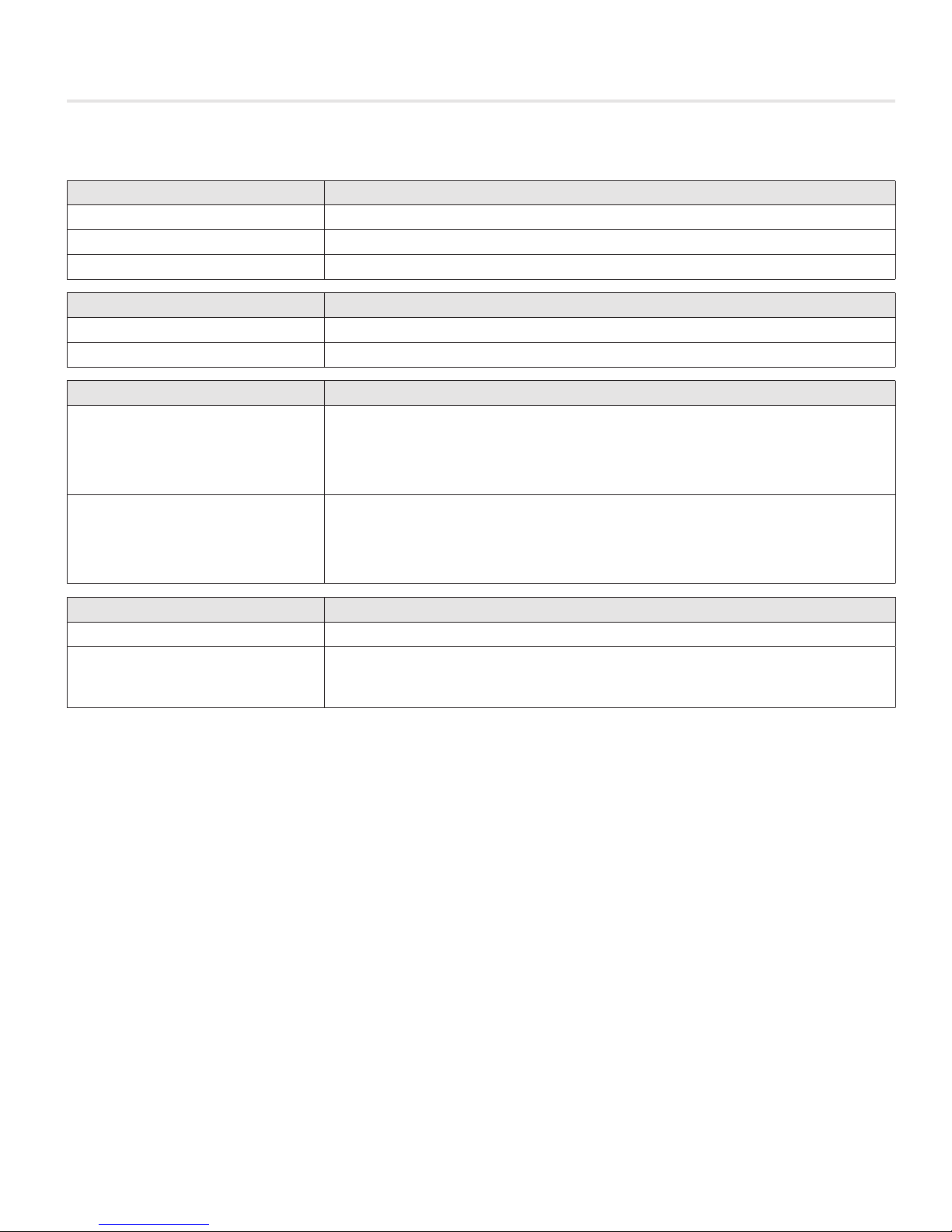
Input/Output Description
24VAC Binary Outputs Description
BO – DPR OPN Plenum damper open. Used for floating point actuators.
BO – DPR CLO Plenum damper closed. Used for floating point actuators.
BO – AUX Aux binary output available.
Analog Outputs
AO – Heat Signal sent to LFGH diffusers (0-10VDC)
AO – Aux Aux analog output available (0-10VDC)
Analog 0-10VDC Inputs
Can be configured (along with AI5) to control the UMC3 from a third party
AI4 – Cooling
AI5 – Heating
thermostat. In this configuration, AI4 is the 0-10VDC cooling load input.
Can also be used for simple voltage monitoring when analog
inputs are not configured as control source.
Can be configured (along with AI4) to control the UMC3 from a third party
thermostat. In this configuration, AI5 is the 0-10VDC cooling load input.
Can also be used for simple voltage monitoring when analog
inputs are not configured as control source.
Additional Inputs
AI1 – 5VDC Sensor Typically used for voltage monitoring over BACnet network.
Analog Input for temperature probe hookup with 10k Type J Thermistor.
THERM
Typically used for temperature monitoring over BACnet network.
Can also be configured for heat/cool changeover if required.
6
UNDERFLOOR MODUFLEX CONTROLLER - Manual | priceindustries.com
UNDERFLOOR MODUFLEX CONTROLLER
INSTALLATION & MOUNTING INSTRUCTIONS
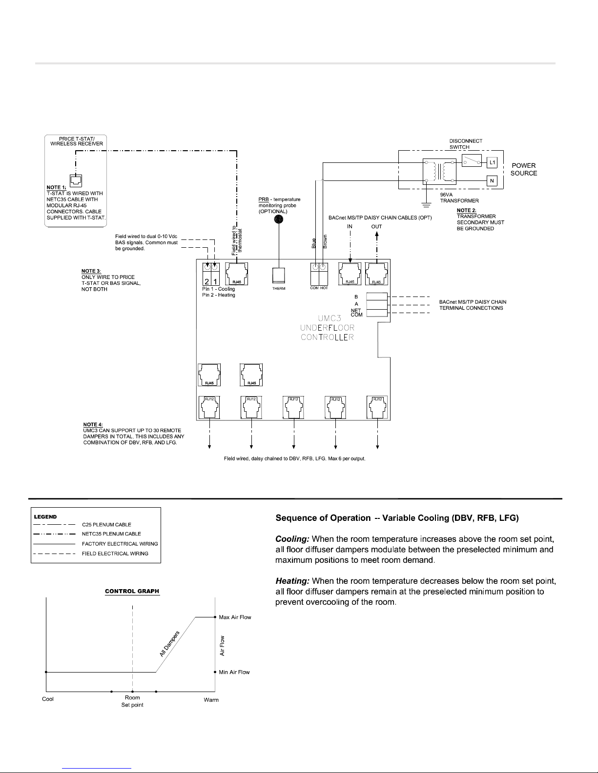
Wiring
Below is an example of a typical UMC3 layout.
priceindustries.com | UNDERFLOOR MODUFLEX CONTROLLER - Manual
7
 Loading...