

Price ULTRASUITE ARRAY Installation Manuals
MANUAL – INSTALLATION
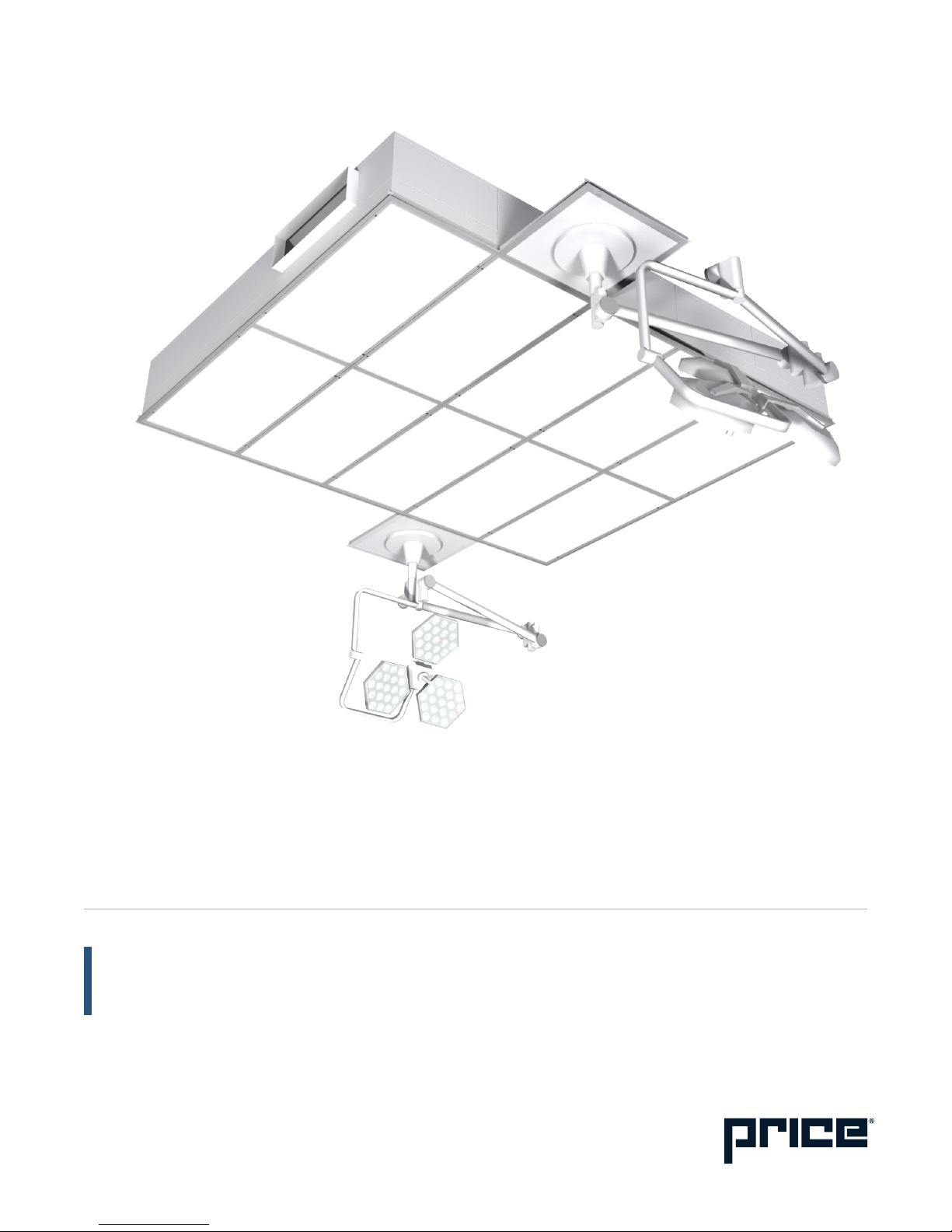
ULTRASUITE ARRAY
Operating Room Diffuser System with LED Lighting
v100 – Issue Date: 09/07/18
© 2018 Price Industries Limited. All rights reserved.

ULTRASUITE ARRAY
TABLE OF CONTENTS
Product Overview ........................................................... 1
Pre-installation Instructions and Checklist .................2
Installation Instructions
Luminaire Mounting and Installation ...............................3
Remote Driver Cabinet Mounting and Installation .......... 9
Electrical Connections ................................................. 10
ULTRASUITE ARRAY
PRODUCT OVERVIEW
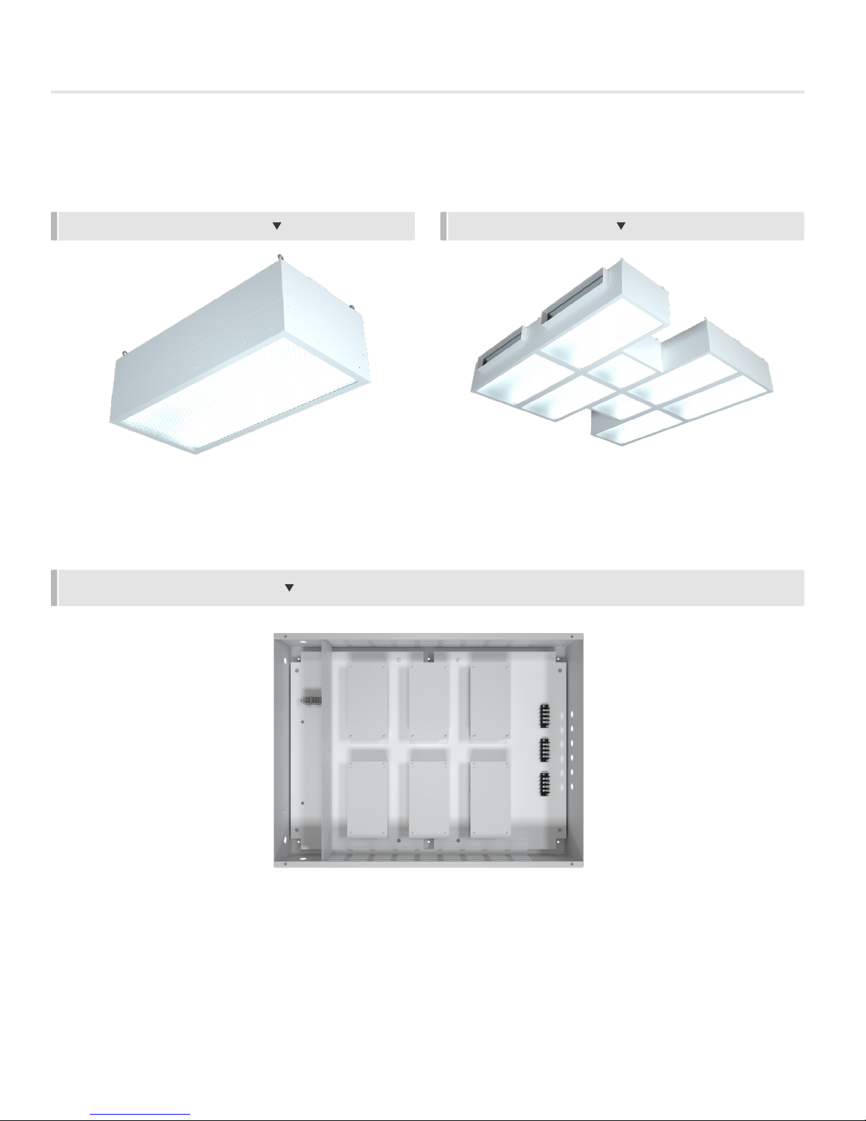
1. The Price Ultrasuite Assembly (USA) luminaire modules will either be:
• A stand-alone module (fig. 1); or
• An array of module assemblies (fig 2)
FIGURE 1: STAND-ALONE MODULE FIGURE 2: MODULE ARRAY
2. The luminaire(s) will come with a remote LED driver cabinet with pre-wired driver connections (fig. 3). The quantity of drivers
varies with the size of the luminaire system.
NOTE: Enclosure cover not shown in image
FIGURE 3: REMOTE DRIVER CABINET
priceindustries.com | ULTRASUITE ARRAY - Manual
1

ULTRASUITE ARRAY
PRE-INSTALLATION INSTRUCTIONS AND CHECKLIST
Read and Save These Instructions
Warning
• To reduce the risk of fire, electrical shock, or injury to persons, observe the following:
• Installation work and electrical wiring must be done by a qualified person(s) in accordance with all applicable codes
and standards, including fire-rated construction.
• Unit must be used in supply applications only, and access above the ceiling is required.
Before you start
• Inspect all cartons and boxes for flaws and shipping damage.
• If anything is found to be damaged, contact the shipping company and file a freight claim.
• Review Price project specific submittals to ensure booms are located in the correct locations (recommended to measure
and chalk outline of ceiling system on floor).
• If drywall perimeter is installed prior to the system, ensure that the opening is cut to the correct dimensions (as per the
submittal), and is square on all corners.
• Ensure all tools (as listed below) are on site and ready for use.
• A minimum of two (2) people will be required to install this system.
Required Tools/Parts
• To be supplied by contractor.
• (2+) 8 ft. ladders or scaffolding
• Laser level
• Cordless drill/impact
• #8 self-tapping screws (1/2 in. maximum length)
• Screwdriver bit(s) to suit self-tapping screws
• Allen keys (5/32 in. and 3/16 in.)
• Damp cloth(s) (for cleaning)
• Utility knife
• Chalk line
• Pliers with wire cutter
• Tape measure
• Clamps/locking plier
• Pre-stressed 12 gauge suspension wire (or approved alternative) with necessary equipment to hang wire
• Supplied by Price:
• Job specific submittal drawing showing all sizes and dimensions of module assembly sections
• Luminaire module sub-assembly sections (refer to job submittal drawing for quantity and sizes)
• Remote driver cabinets (refer to job specific submittal drawing for quantity, sizes and field wiring connection details)
• Dimmer switches (refer to job specific submittal drawing for quantity and field wiring connections)
• HGWC Perimeter ceiling sections (if applicable)
• 1/32 in. x 3/4 in. (t x w) white gasket tape – for between modules (Part Number 042373 004)
• The following supplied for bolting module assemblies together:
• Bolt
• Metal washer
• Lock nut assembly
2
ULTRASUITE ARRAY - Manual | priceindustries.com
ULTRASUITE ARRAY
INSTALLATION INSTRUCTIONS
Luminaire Mounting and Installation
Step 1: Snap chalk line on the floor to outline locations and sizes of module assembly sections.
Step 2: Unpack module assembly sections and lay them out on the floor as per the job specific submittal package and determine
remote driver cabinet mounting location. Ensure adequate wire length is available to wire to the remote cabinet. Refer to page 9
for remote driver cabinet mounting and installation and page 10 for electrical connections.
NOTE: Ensure floor surface is clean and free of debris that could damage the product finish.
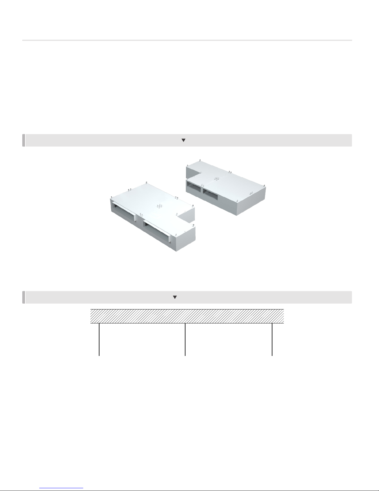
NOTE: Ensure that adjacent module assembly sections have mated inlets in the correct locations (fig. 4).
FIGURE 4: ENSURE MATED INLETS ARE ALIGNED CORRECTLY
Step 3: Attach lengths of pre-stressed 12 gauge suspension wire to the slab or structural steel (fig. 5) above the ceiling according
to ASTM C636, and any applicable local codes, ensuring that a minimum of four (4) suspensions points are used per module.
FIGURE 5: SUSPENSION WIRE ATTACHED TO STRUCTURE
NOTE: Ensure that the perimeter drywall (if installed) and other equipment are installed at the correct heights using a laser level.
Step 4: Extend hanger wires 6 in. below the top of the plenum (refer to job specific submittal for plenum height) and snip to length
as required.
priceindustries.com | ULTRASUITE ARRAY - Manual
3
ULTRASUITE ARRAY
INSTALLATION INSTRUCTIONS
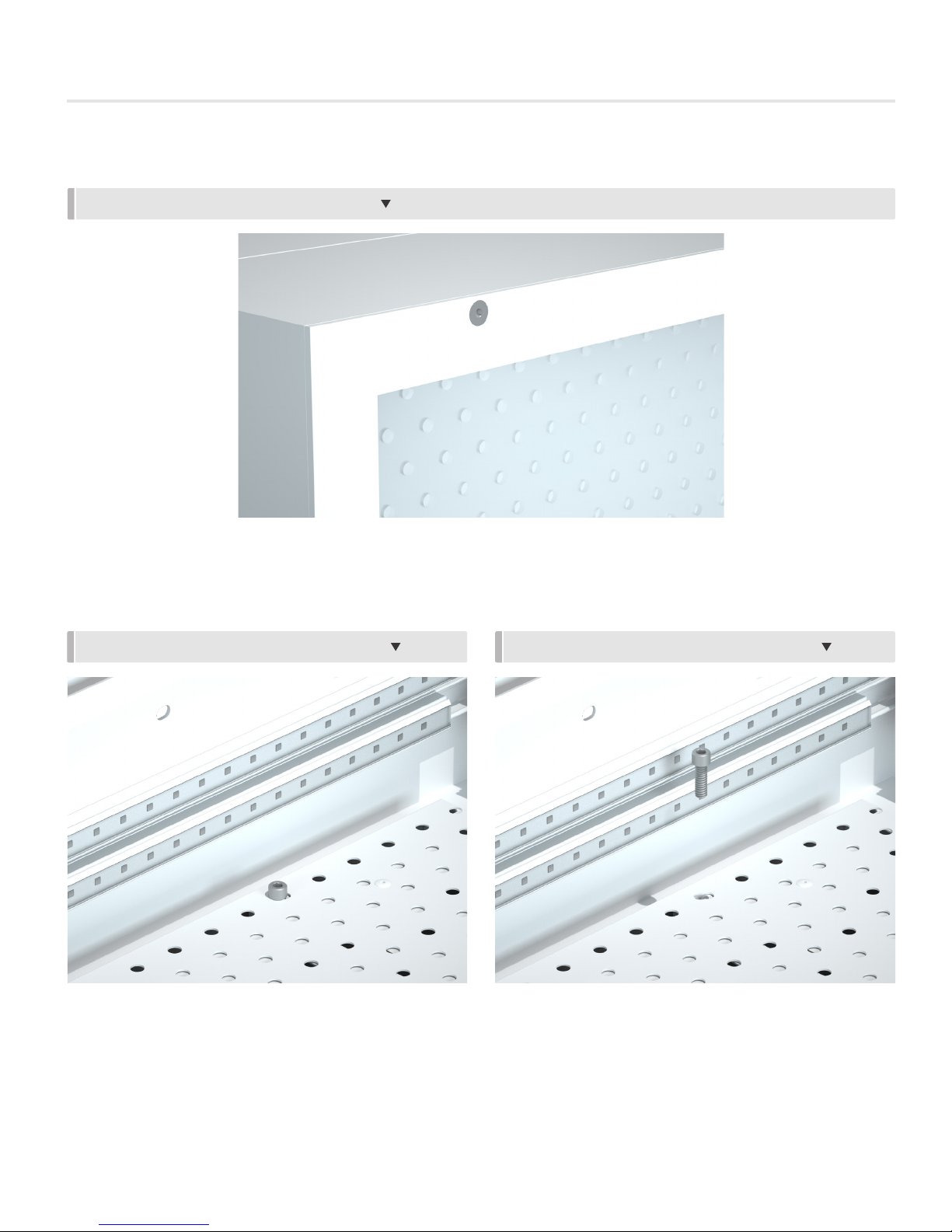
Step 5: Remove the plastic diffuser face by using a 5/32 in. Allen key, removing the countersunk flat head screw (fig. 6).
FIGURE 6: PLASTIC DIFFUSER FACE REMOVAL
Step 6: Using a 3/16 in. Allen key, unscrew the damper mounting screw to release the aperture plate damper for access to the
plenum (fig. 7, 8, 9, 10).
FIGURE 7: LOOSEN DAMPER MOUNTING SCREW FIGURE 8: REMOVE DAMPER MOUNTING SCREW
4
ULTRASUITE ARRAY - Manual | priceindustries.com
 Loading...