

Page 1
MANUAL – INSTALLATION, OPERATION, AND MAINTENANCE
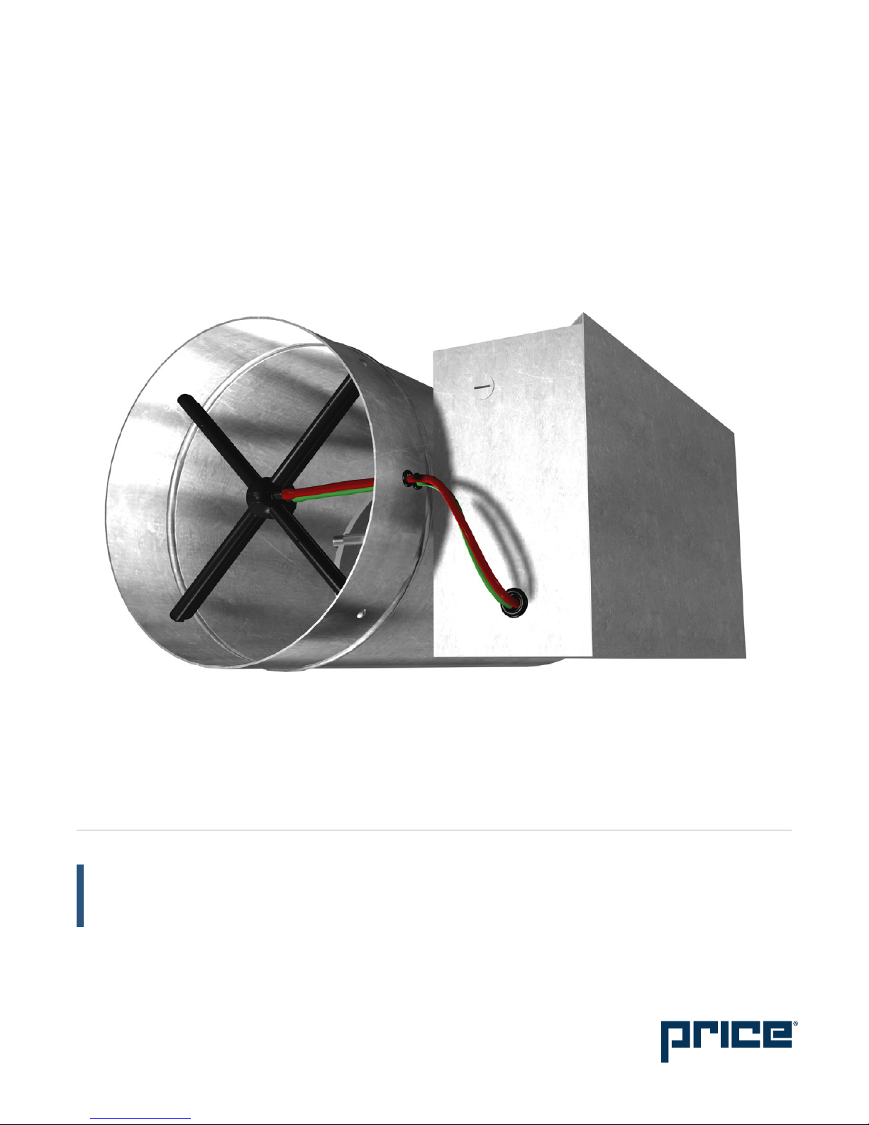
Air Volume Control Valve
RDV / RDVQ Series
v004 – Issue Date: 07/14/16
© 2016 Price Industries Limited. All rights reserved.
Page 2

AIR VOLUME CONTROL VALVE
TABLE OF CONTENTS
Product Overview
General ......................................................................... 1
Receiving Inspection ..................................................... 1
Wiring ........................................................................... 1
Installation Instructions
Installing the RDV/RDVQ 5000 Terminal Unit ................. 2
Air Volume Ranges ........................................................ 2
SP300 Cal. Curves - RDV ............................................. 3
SP300 Cal. Curves - RDVQ w/Absorptive Silencer ........ 4
SP300 Cal. Curves - RDVQ w/Packless Silencer ........... 5
Page 3
OPTIONAL
NEMA1
CONTROLS
ENCLOSURE
(SEE NOTE)
OPTIONAL
NEMA1
CONTROLS
ENCLOSURE
(SEE NOTE)
20”
(508)
MULTI-POINT SENSOR
C/W GAUGE TAPS
PACKLESS
SILENCER
20”
(508)
4
3
/4” (121)
9
1
/2” (241)
9
1
/2” (241)
MULTI-POINT SENSOR
C/W GAUGE TAPS
ABSORPTIVE
SILENCER
DIA = A + 8”
4
3
/4” (121)
DIA = A - 1/8” (3)
DIA = A -
1
/8” (3)
181/2” (470)
INLET SILENCER
SECTION
DIA = A - 1/8” (3)
AIR
FLOW
2”
(51)
B
2” (51)
36” (914)
CONNECTION COLLAR
UP
AIR VOLUME CONTROL VALVE
PRODUCT OVERVIEW
General
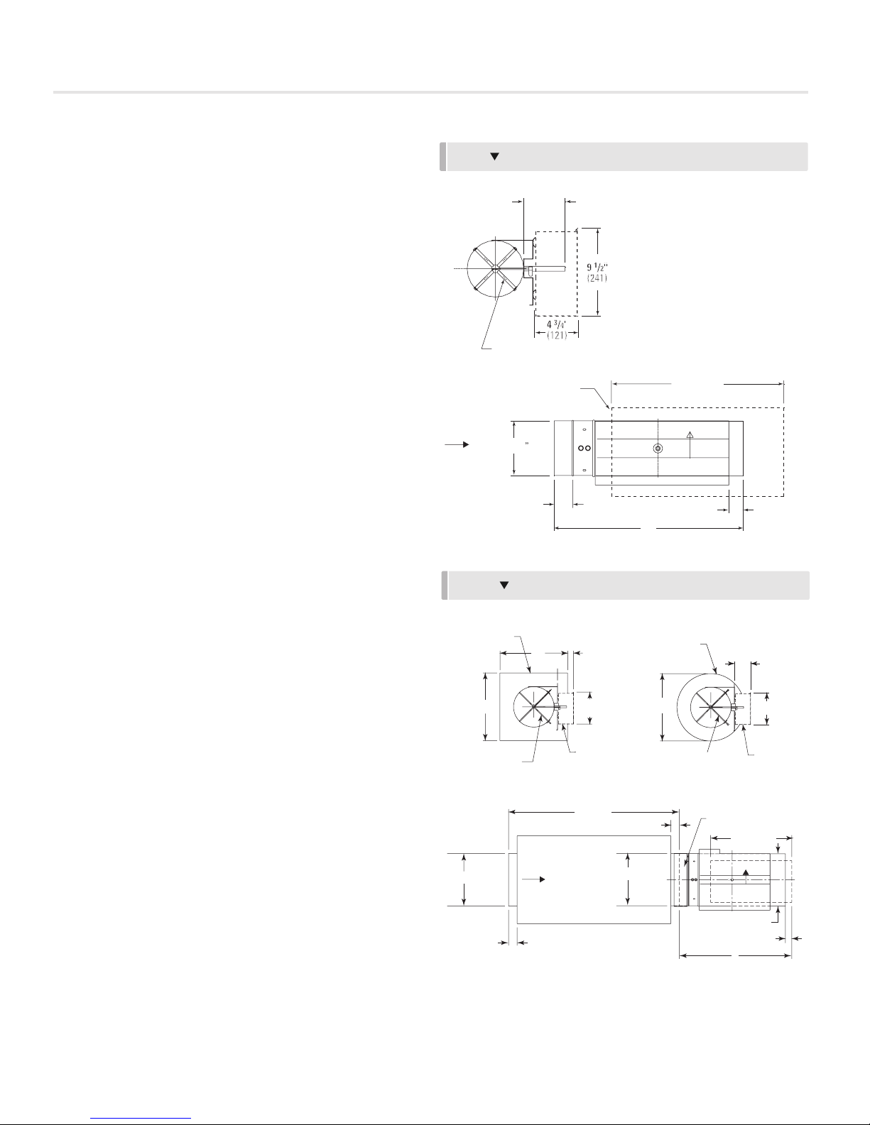
The RDV/RDVQ is supplied with the duct, damper, and airflow
sensor. The RDV/RDVQ assembly is designed to accept Direct
Digital Controls (DDC) for VAV pressure independent operation.
The terminal unit controls are supplied by the controls
contractor and either factory or field mounted and wired. For
information concerning controls, components, sequence of
operation, etc., please refer to the documentation provided by
the controls contractor.
Receiving Inspection
After unpacking the assembly, check it for shipping damage.
If any shipping damage is found, report it immediately to the
delivering carrier. During unpacking and installation do not
handle by the inlet velocity sensor, damper shaft, or tubing.
Damage may result.
Wiring
If controls have been factory mounted, a wiring diagram
will be included with the unit indicating the factory mounted
components. For field wiring of room sensors and other
accessories, refer to the controls contractor's documentation.
If the controls have been field mounted, refer to the controls
contractor's documentation for all wiring information.
Damper rotation is always clockwise to the open position.
An identification mark on the end of the shaft indicates the
damper position.
The factory supplied sensing lines are color coded. Red
indicates the total pressure or ”HI“ line which should be
located on the upstream side. Green indicates the static
pressure or ”LO“ line which should be located on the
downstream side.
An optional protective enclosure may be provided to house
the terminal unit control components. The enclosure cover is
removable with two sheet metal screws.
RDV
AIR
DIA = A - 1/8” (3)
FLOW
RDVQ
PACKLESS
SILENCER
20”
(508)
MULTI-POINT SENSOR
C/W GAUGE TAPS
DIA = A - 1/8” (3)
4 1/2” (114)
DAMPER SHAFT
MULTI-POINT SENSOR
C/W GAUGE TAPS
FOR PNEUMATIC CONTROLS
NEMA1 OPTIONAL
CONTROLS ENCLOSURE
20”
(508)
AIR
FLOW
2”
(51)
3
/4” (121)
4
1
9
/2” (241)
OPTIONAL
NEMA1
CONTROLS
ENCLOSURE
(SEE NOTE)
36” (914)
INLET SILENCER
SECTION
ABSORPTIVE
SILENCER
DIA = A + 8”
MULTI-POINT SENSOR
C/W GAUGE TAPS
2” (51)
DIA = A - 1/8” (3)
18 1/2” (470)
UP
CONNECTION COLLAR
DIA = A -
1 1/2” (38)
4
1
/2” (241)
9
OPTIONAL
NEMA1
CONTROLS
ENCLOSURE
(SEE NOTE)
181/2” (470)
UP
1
/8” (3)
3
/4” (121)
B
priceindustries.com | AIR VOLUME CONTROL VALVE - Manual
1
Page 4
AIR VOLUME CONTROL VALVE
INSTALLATION INSTRUCTIONS
Installing the RDV/RDVQ Terminal Unit
The basic RDV is light enough that it can be supported by the
ductwork in which it is installed. The RDVQ is supplied with
silencers and should be supported directly. Use the support
method prescribed for the round duct in the job specifications.
NOTE: For optimum performance there should be a minimum
of three duct diameters of straight inlet duct, same size as the
inlet, between the inlet and any transition, take off or fitting.
The assembly should be mounted right side up. It should be
level within ±10 degrees of horizontal, both parallel to the
air flow and at right angles to the air flow. The side of the
assembly is labelled with an arrow indicating UP. Do not mount
the control side of the assembly tight to a wall, pipe or other
obstruction. Allow sufficient room for access to the controls
If the RDV/RDVQ is mechanically fastened to the duct work an
approved duct sealer should be used to seal all connections.
Damper rotation is always clockwise to the open position.
An identification mark on the end of the shaft indicates the
damper position.
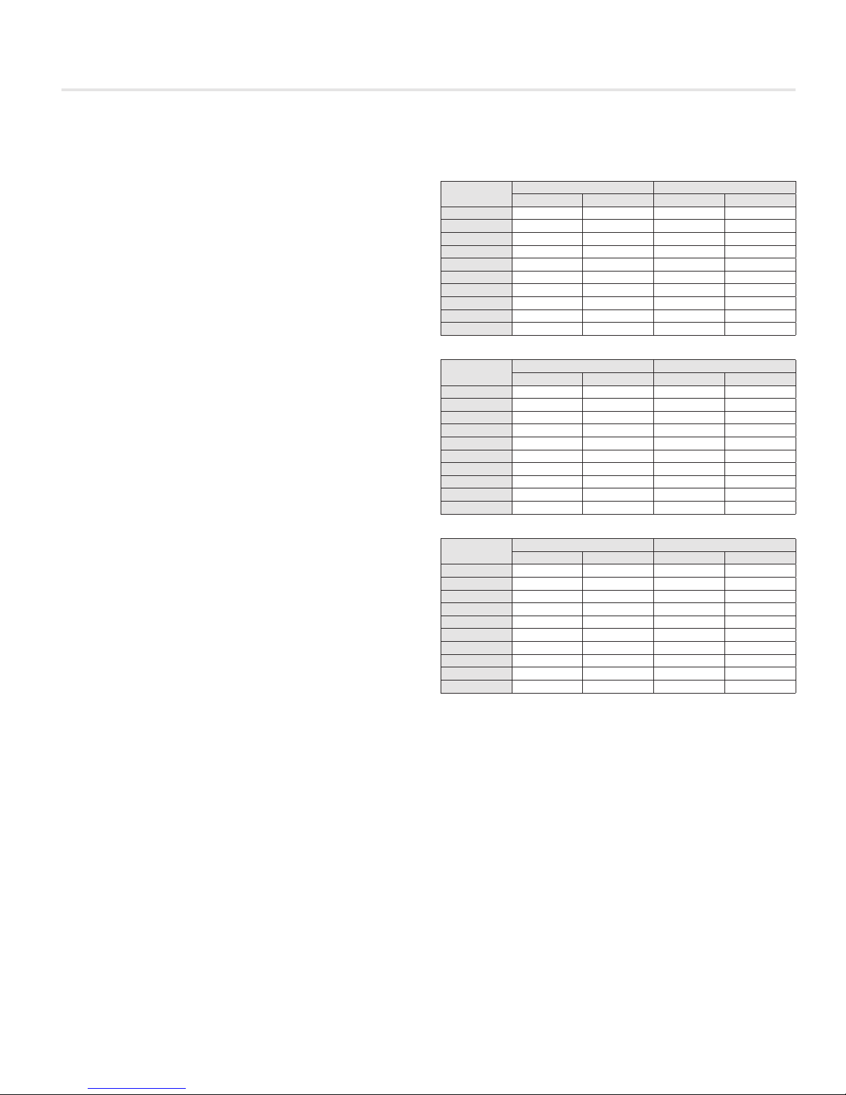
The air volume ranges listed are recommended for optimum
performance. A minimum value of zero is also acceptable if no
heating coils are attached.
Selection of air flow limits below the listed values is not
recommended. Stability and accuracy may not be acceptable
at lower than recommended air flow limits. The actual
performance will vary depending on the terminal unit controls
supply.
Air Volume Ranges
RDV Basic
Size
4 45 225 21 106
5 60 350 28 165
6 65 450 31 212
7 95 650 45 307
8 125 800 59 378
9 160 1050 76 496
10 210 1350 99 637
12 300 2100 142 991
14 430 3000 203 1416
16 575 4000 271 1888
RDVQ - Absorptive
Size
4 -- -- -- --
5 -- -- -- --
6 80 450 38 212
7 110 650 52 307
8 160 800 76 378
9 200 1050 94 496
10 270 1350 127 637
12 350 2100 165 991
14 500 3000 236 1416
16 650 4000 307 1888
RDVQ - Absorptive
Size
4 -- -- -- --
5 -- -- -- --
6 65 380 31 179
7 95 650 45 307
8 125 790 59 373
9 160 1050 76 496
10 210 1350 99 637
12 300 2025 142 956
14 430 2400 203 1133
16 575 3425 271 1616
CFM L/S
MIN MAX MIN MAX
CFM L/S
MIN MAX MIN MAX
CFM L/S
MIN MAX MIN MAX
2
AIR VOLUME CONTROL VALVE - Manual | priceindustries.com
NOTE: Factory calibrated controls must be selected
within the above flow range limits. A minimum value
of zero is also available. When an auxiliary flow
setting is specified, the value must be greater than
the minimum setting and within the range limits.
On controls mounted by Price but supplied by others, the air
volume ranges are guidelines only.
Selection of air flow limits below the listed values is not
recommended. Stability and accuracy may not be acceptable
at lower than recommended air flow limits. The actual
performance will vary depending on the terminal unit controls
supplied.
Page 5
AIR VOLUME CONTROL VALVE
INSTALLATION INSTRUCTIONS
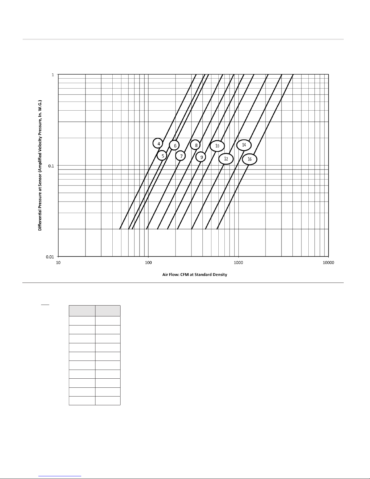
SP300 Calibration Curves - RDV
Calibration Equation
2
VP =
VP - differential
Q - air flow
K - calibration
Q
( )
K
pressure
at sensor,
inches w.g.
rate, cfm
at standard
density.
constant
Unit Size K
4 340
5 426
6 468
7 673
8 890
9 1155
10 1487
12 2141
14 3045
16 4074
Notes:
1. Gauge taps are normally supplied
with the pneumatic controls to allow
field measurement of the differential
pressure at the sensor with a
manometer, magnahelic or other
measuring device.
If the terminal velocity controls utilize
a flow-through transducer, a proper
velocity pressure reading will NOT
be read at the gauge taps and the
calibration curves CANNOT be used
for field measurement. The flowthrough transducer operates on the
principle of mass flow rather than
pressure differential.
priceindustries.com | PRICE FUME HOOD CONTROLLER - Manual
Controls utilizing a dead-ended
pressure transducer will allow field
measurement with the gauge taps
and calibration curves provided.
2. Setting flow limits for a differential
pressure of less than 0.02 inches
in NOT recommended. Stability
and accuracy of flow limits may not
be acceptable due to low velocity
pressure signal. Performance will
vary depending on the terminal unit
controls provided.
3. For field calibration of air flow limits
refer to the control contractors
documentation.
3
Page 6
AIR VOLUME CONTROL VALVE
INSTALLATION INSTRUCTIONS
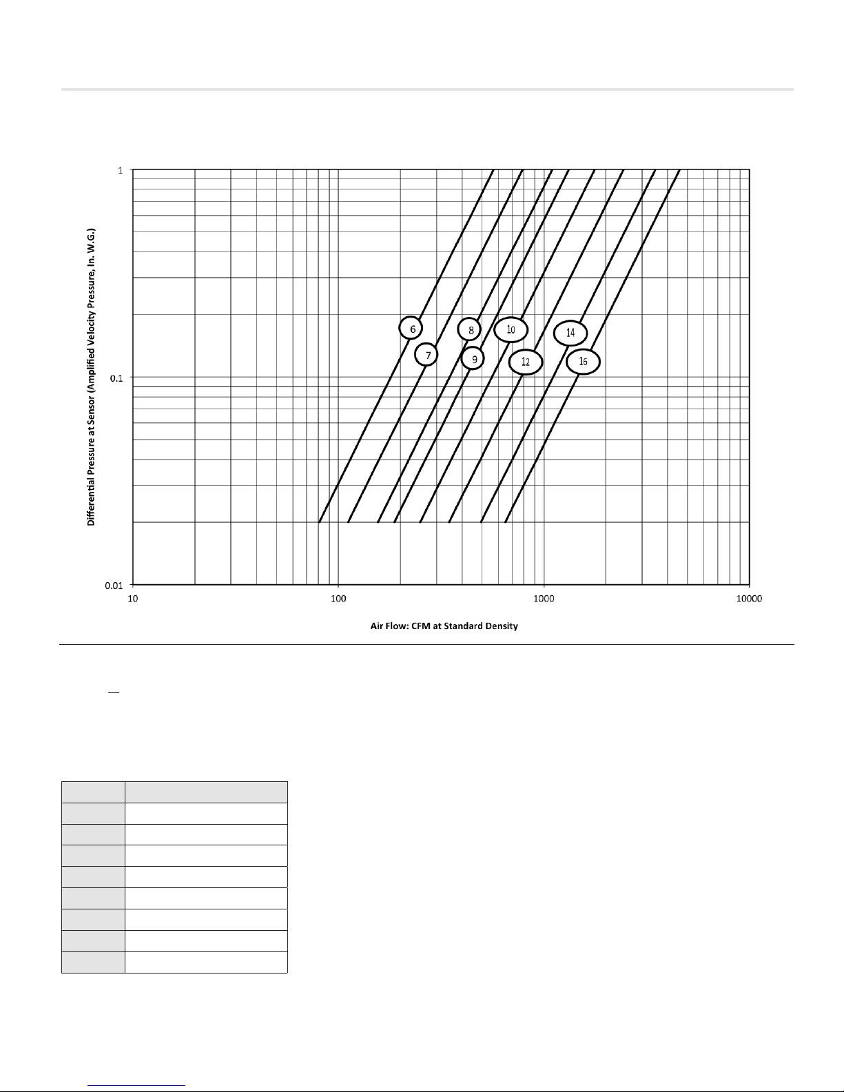
SP300 Calibration Curves - RDVQ w/Absorptive Silencer
Calibration Equation
VP =
Unit Size K
6 570
7 790
8 1100
9 1325
10 1770
12 2450
14 3500
16 4600
4
AIR VOLUME CONTROL VALVE - Manual | priceindustries.com
Q 2
( )
K
VP - differential pressure
at sensor, inches w.g.
Q - air flow rate, cfm at
standard density.
K - calibration constant
Notes:
1. Gauge taps are normally supplied
with the pneumatic controls to allow
field measurement of the differential
pressure at the sensor with a
manometer, magnahelic or other
measuring device.
If the terminal velocity controls utilize
a flow-through transducer, a proper
velocity pressure reading will NOT
be read at the gauge taps and the
calibration curves CANNOT be used
for field measurement. The flowthrough transducer operates on the
principle of mass flow rather than
pressure differential.
Controls utilizing a dead-ended
pressure transducer will allow field
measurement with the gauge taps
and calibration curves provided.
2. Setting flow limits for a differential
pressure of less than 0.02 inches
is NOT recommended. Stability
and accuracy of flow limits may not
be acceptable due to low velocity
pressure signal. Performance will
vary depending on the terminal unit
controls provided.
3. For field calibration of air flow limits
refer to the control contractors
documentation.
Page 7
AIR VOLUME CONTROL VALVE
INSTALLATION INSTRUCTIONS
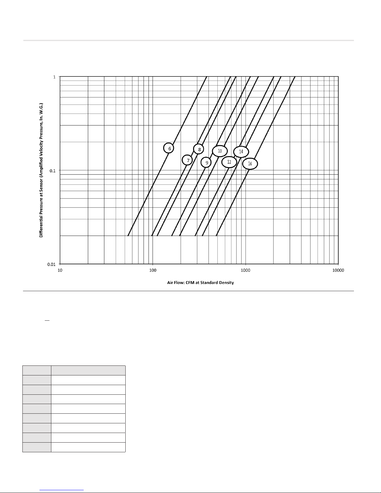
SP300 Calibration Curves - RDVQ w/Packless Silencer
Calibration Equation
VP =
Unit Size K
6 382
7 690
8 790
9 1130
10 1380
12 2025
14 2415
16 3425
Q 2
( )
K
VP - differential pressure
at sensor, inches w.g.
Q - air flow rate, cfm at
standard density.
K - calibration constant
Notes:
1. Gauge taps are normally supplied
with the pneumatic controls to allow
field measurement of the differential
pressure at the sensor with a
manometer, magnahelic or other
measuring device.
If the terminal velocity controls utilize
a flow-through transducer, a proper
velocity pressure reading will NOT
be read at the gauge taps and the
calibration curves CANNOT be used
for field measurement. The flowthrough transducer operates on the
principle of mass flow rather than
pressure differential.
priceindustries.com | AIR VOLUME CONTROL VALVE - Manual
Controls utilizing a dead-ended
pressure transducer will allow field
measurement with the gauge taps
and calibration curves provided.
2. Setting flow limits for a differential
pressure of less than 0.02 inches
is NOT recommended. Stability
and accuracy of flow limits may not
be acceptable due to low velocity
pressure signal. Performance will
vary depending on the terminal unit
controls provided.
3. For field calibration of air flow limits
refer to the control contractors
documentation.
5
Page 8

This document contains the most current product information as of this printing.
For the most up-to-date product information, please go to priceindustries.com
© 2016 Price Industries Limited. All rights reserved.
 Loading...