

Price FHC, FHMX Installation Manual

MANUAL – INSTALLATION
Fume Hood Contoller/Monitor
FHC/FHMX Series
v300 – Issue Date: 05/31/17
© 2017 Price Industries Limited. All rights reserved.
Firmware Version: 1.6.0

FUME HOOD CONTROLLER / MONITOR
TABLE OF CONTENTS
Section 1 - Introduction
Product Overview .......................................................... 1
Features ........................................................................ 1
Fume Hood Interface (FHI) Features .............................2
Sidewall Sensor (SWS) Features .................................... 2
Sash Position Sensor (SPS) Features ............................2
Presence Sensor (PS) Features .....................................2
Section 2 - Installation & Mounting
Fume Hood Controller (FHC) Installation & Mounting .....3
Fume Hood Monitor (FHMX) Installation & Mounting ..... 4
Sash Position Sensor (SPS) Installation & Mounting ...... 5
Sidewall Sensor (SWS) Installation & Mounting .............. 7
Presence Sensor (PS) Installation and Mounting ........... 8
Wiring Diagram ............................................................. 9
Fume Hood Location Considerations .......................... 11
Section 3 - Sash, Sidewall & Hybrid Configuration
Control Settings ..........................................................12
Fume Hood Interface (FHI) .......................................... 13
FHI - Initial Start Up ..................................................... 13
Information Menu ........................................................ 14
Service Menu .............................................................. 14
IMPORTANT NOTES
CAUTION
This mark indicates an important point for the proper
function of the fume hood and the FHC. Improper
installation or setup may cause unit failure and
contamination of the laboratory space. Pay close
attention to all caution points throughout this manual.
Application Support
P: 204.654.5604
E: criticalcontrols@priceindustries.com
W: www.pricecriticalcontrols.com
Technical Support
P: 866.884.3524
E: pccfieldservice@priceindustries.com
Section 4 - Interface And Menus
Control/Monitor ........................................................... 15
Alarm Points ................................................................ 17
Occupancy ................................................................. 17
Input ........................................................................... 18
Output ........................................................................ 19
Network ...................................................................... 21
FHI Setup .................................................................... 21
Diagnostic ................................................................... 22
Section 5 - Setup Wizard
Setup Wizard .............................................................. 23
Section 6 - Balance And Verification
Balance & Verification .................................................. 25
Section 7 - BACnet Points List
BACnet Points List ...................................................... 26
pricecriticalcontrols.com | FUME HOOD CONTROLLER / MONITOR - Manual

FUME HOOD CONTROLLER / MONITOR
SECTION 1 - INTRODUCTION
Product Overview
Laboratory fume hoods serve as
ventilation systems that efficiently
exhaust chemical vapors, mist, and
fumes. Fume hoods also provide a
barrier protecting occupants from
certain reactions, spills, and even fires.
In most cases special fans exhaust the
fumes outside, which greatly dilute their
concentration and reduce their harmful
effects. In some cases a specialized
scrubber is also required to remove the
vapors from the exhaust air.
Fume hoods require constant exhaust
airflow to ensure that none of the air
entering the fume hood ever escapes
back into the laboratory space. This
ensures the safety of the user and of
any other occupants of the room or
building. The exhaust airflow, measured
in cubic feet per minute (CFM), creates
a face velocity across the sash opening.
This is the industry standard measure
of fume hood safety. Typically the
face velocity of a fume hood must be
between 80 – 100 feet per minute
(FPM), but this can vary based on local
codes or the fume hood design. It is
important to note the required face
velocity for the hood being used.
Features
The Fume Hood Controller (FHC) can ensure a safe working environment by
constantly monitoring and adjusting the exhaust to maintain the correct face velocity.
The main control inputs are sash sensors and sidewall sensors. Sash sensors use a
potentiometer attached to the sash to measure the current height. Face velocity in
feet per minute (FPM) is calculated in real time. Sidewall sensors use an extremely
sensitive, low pressure sensor to measure the negative pressure in the hood
compared to the lab space. The Fume Hood Monitor (FHMX) constantly monitors
the fume hood face velocity and can provide real-time fume hood information to
operators and to the building management system (BMS) over BACnet.
• 16 bit – high speed flash based microprocessor with watch dog timer, brown
out reset
• Multi-stage surge protection against voltage spikes on 24 VAC input
• 2 simple connections to sidewall sensors using RJ-12 jacks
• 3 Sash position inputs (10kΩ)
• 2 binary outputs rated at 0.5 amps each, protected with thermal fuse
(RED LED on trip)
• 1 binary output (dry contact)
• 2 analog outputs (0-10 VDC)
• 2 binary inputs
• Pluggable terminal blocks
• Mnet high-speed fume hood network port
• 1 potentiometer input
• 1 pressure port input
CAUTION
A higher face velocity is not always
safer. Turbulence in the fume hood
can be created by high face velocities
causing issues with spillage/blowback.
1
FUME HOOD CONTROLLER / MONITOR - Manual | pricecriticalcontrols.com
• LED’s for Mnet/Lnet data TX/RX, Mnet/Lnet wiring fault, and RS-45 termination
FUME HOOD CONTROLLER / MONITOR
SECTION 1 - INTRODUCTION
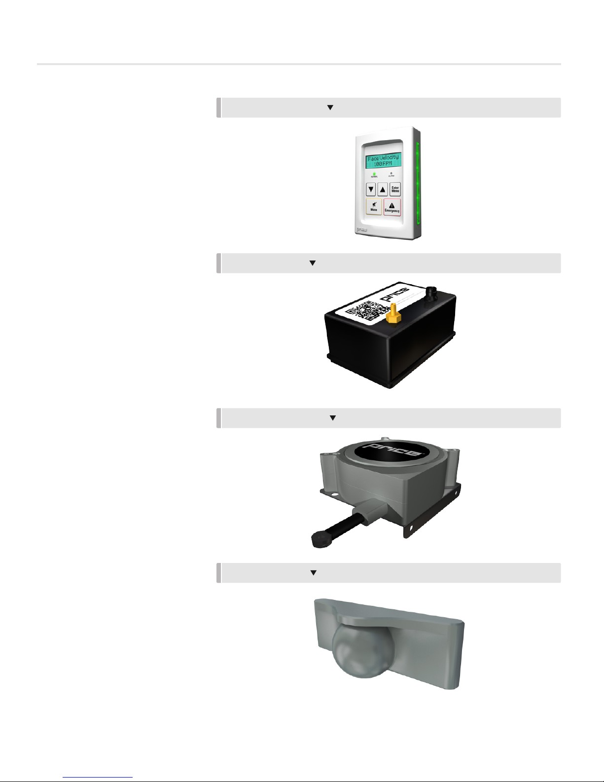
Fume Hood Interface
(FHI) Features
• Backlit 14x2 LCD Interface with true
character display
• LED side bars offer 180 degree
viewing of current fume hood status
• Variety of colors displayed to
indicate fume hood status
• Password protected setup menu
• Easy to use MENU system for fast
and simple setup of system
• Included RJ45 plenum rated cable
for fast, error free hookup
• Setup Wizard – walk through setup
of FHC when first powered up
Sidewall Sensor (SWS) Features
• Ultra Low flow digital temperature
compensated pressure transducer
• 25 ft. sensor cable with quickconnect installation
FUME HOOD INTERFACE
SIDEWALL SENSOR
• Sidewall assembly with easy-tomount hardware
Sash Position Sensor
(SPS) Features
• Ultra long life potentiometer (over
250,000 cycles)
• Stainless steel cable for stability
• Metal mounting ring for stable
installation and reliability
• Thick plastic cover for protection
against airborne chemical agents
Presence Sensor (PS) Features
• Low profile device
• Adjustable coverage pattern
• Sensitive response
SASH POSITION SENSOR
PRESENCE SENSOR
pricecriticalcontrols.com | FUME HOOD CONTROLLER / MONITOR - Manual
2
FUME HOOD CONTROLLER / MONITOR
SECTION 2 - INSTALLATION & MOUNTING
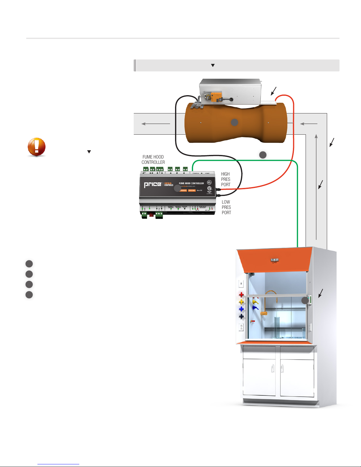
Fume Hood Controller (FHC)
Installation & Mounting
• Open the controls enclosure on the
Price Venturi Valve that is installed in
the fume hood exhaust duct.
• Follow the wiring diagram found
on page 10 for the FHC electrical
installation.
CAUTION
The Fume Hood Controller is factory
mounted on the valve when ordered
with a Price Venturi Valve. Only electrical
installation is required.
Ensure the valve is facing the correct
direction and is mounted in the correct
orientation (vertical or horizontal).
INSTALLATION & MOUNTING
FUME HOOD
CONTROLLER
2
1
HIGH
PRESSURE
PORT
LOW
PRESSURE
PORT
4
RJ-45 PLENUM
RATED FHI CABLE
VENTURI
VALVE
DUCT
AIRFLOW
DIRECTION
Required items:
1
Venturi Valve
2
Fume Hood Controller
3
Fume Hood Interface
4
RJ-45 Plenum Rated FHI Cable
FUME HOOD
INTERFACE
3
3
FUME HOOD CONTROLLER / MONITOR - Manual | pricecriticalcontrols.com

FUME HOOD CONTROLLER / MONITOR
SECTION 2 - INSTALLATION & MOUNTING
Fume Hood Monitor (FHMX)
Installation & Mounting
• The FHMX may arrive valve
mounted (see FHC Installation
& Mounting) or in a panel mount
controls enclosure. Open the
controls enclosure to access the
FHMX.
• Follow the wiring diagram found
on page 9 for the FHMX electrical
installation.
CAUTION
The Fume Hood Monitor is factory
mounted in an enclosure when ordered.
Only electrical installation is required.
Ensure that the panel-mount enclosure
is mounted in a location that can be
accessed for electrical installation.
INSTALLATION & MOUNTING
FUME HOOD
MONITOR
1
3
RJ-45 PLENUM
RATED FHI CABLE
DUCT
AIRFLOW
DIRECTION
Required items:
1
Fume Hood Monitor
2
Fume Hood Interface
3
RJ-45 Plenum Rated FHI Cable
FUME HOOD
INTERFACE
2
pricecriticalcontrols.com | FUME HOOD CONTROLLER / MONITOR - Manual
4
FUME HOOD CONTROLLER / MONITOR
SECTION 2 - INSTALLATION & MOUNTING
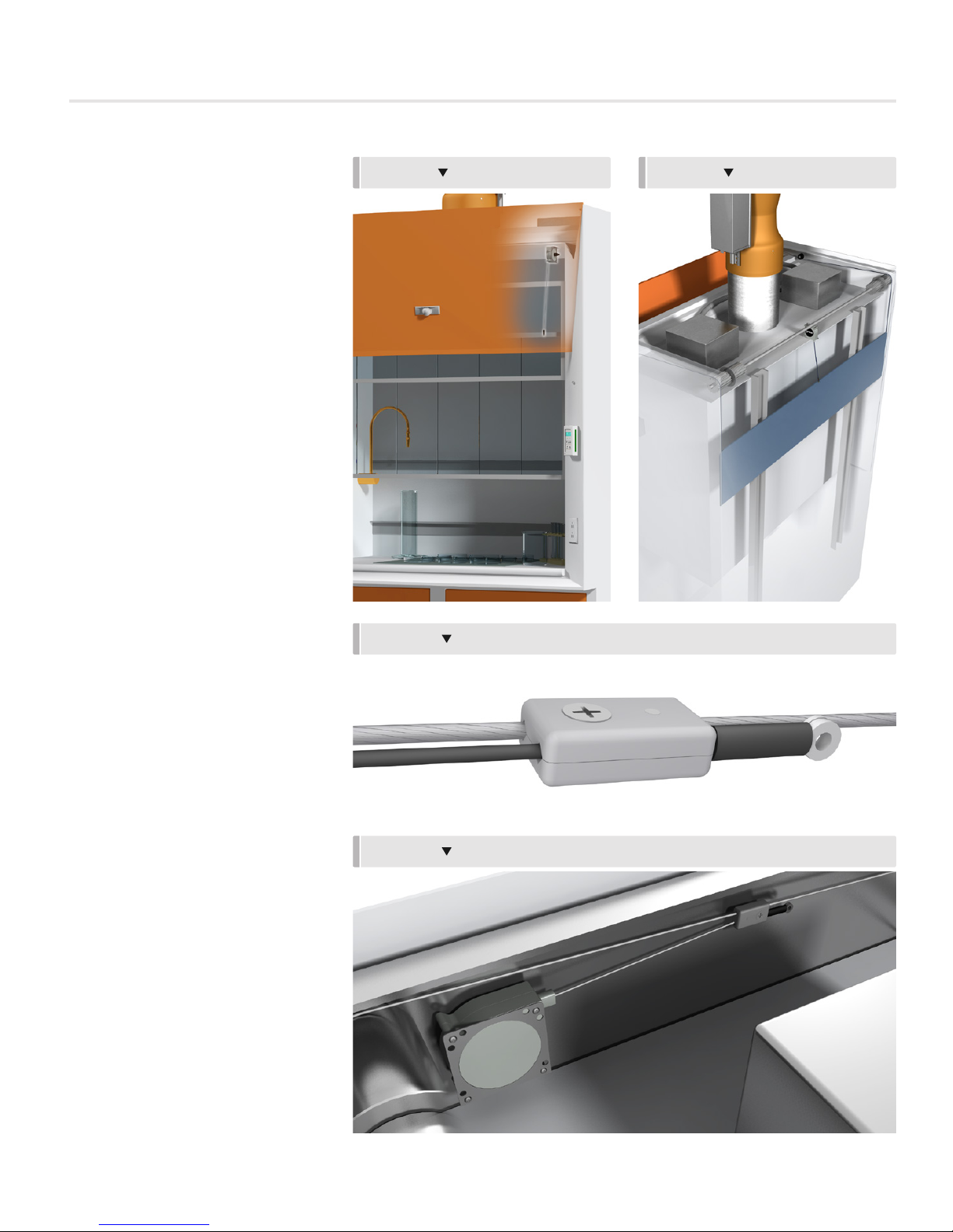
Sash Position Sensor (SPS)
Installation & Mounting
The sash sensor can be mounted in
one of four ways. Option A mounts
directly above the sash outside of the
fume hood. Options B and C mount to
the counter weight cable, and Option D
mounts directly in the hood.
Option A) Mount the sash sensor
above the sash as shown in Figure 1.
• Ensure the cable is free from
obstruction along the entire length
of sash movement.
• Ensure that the mounting position
of the end of the cable will not pass
above the sash sensor even at the
maximum sash height.
• Run the sensor cable back to the
FHC mounted on the venturi valve
or the FHMX.
Option B) Mount the sash sensor on
the top of the fume hood as shown in
Figure 2.
• Ensure the cable is free from
obstruction along the entire length
of sash movement.
FIGURE 1 FIGURE 2
FIGURE 3
• The sensor cable may be attached
directly to the counter weight.
This configuration may be desired
when the sash connects to the
counterweight with a belt and pulley
system.
• Run the sensor cable back to the
FHC mounted on the venturi valve
or the FHMX.
Option C) Mount the sash sensor on
the top of the fume hood as shown in
Figure 3 and 4.
• Ensure the cable clamp does not
pass around a pulley.
• Run the sensor cable back to the
FHC mounted on the venturi valve
or the FHMX.
• Ensure the sensor cable travels
parallel to the counter weight cable.
5
FUME HOOD CONTROLLER / MONITOR - Manual | pricecriticalcontrols.com
FIGURE 4

FUME HOOD CONTROLLER / MONITOR
SECTION 2 - INSTALLATION & MOUNTING
Option D) Mount the sash sensor on
the inside wall of the fume hood as
shown in Figure 5. This is the least
preferable mounting option, as the
sensor is directly in the exhaust air
stream.
• Ensure that the sensor and cable
to not interfere with the mechanical
operation of the fume hood sash.
• Ensure the sensor is as close to the
sash as possible so that the cable is
completely parallel to the sash in all
positions.
• Raise the sash to the fully open
position (not just the working
height). Screw the metal ring into
the sash. Ensure that the sensor is
mounted higher than the fully open
position of the sash.
• Once mounted, raise and lower the
sash several times to ensure that
the cable is clear of all obstructions
and moves freely with the sash.
FIGURE 5
• Run the sensor cable back to the
FHC mounted on the venturi valve
or the FHMX.
CAUTION
The sash position sensor cable must be
mounted as close to parallel as possible
with the direction of the sash movement.
Any angle can cause improper sash
height readings and result in poor
control.
CAUTION
If only one SPS is required, the
SPS must be wired into the SASH
POSITION SENSOR #1 port on the
FHC/FHMX.
pricecriticalcontrols.com | FUME HOOD CONTROLLER / MONITOR - Manual
6
FUME HOOD CONTROLLER / MONITOR
SECTION 2 - INSTALLATION & MOUNTING
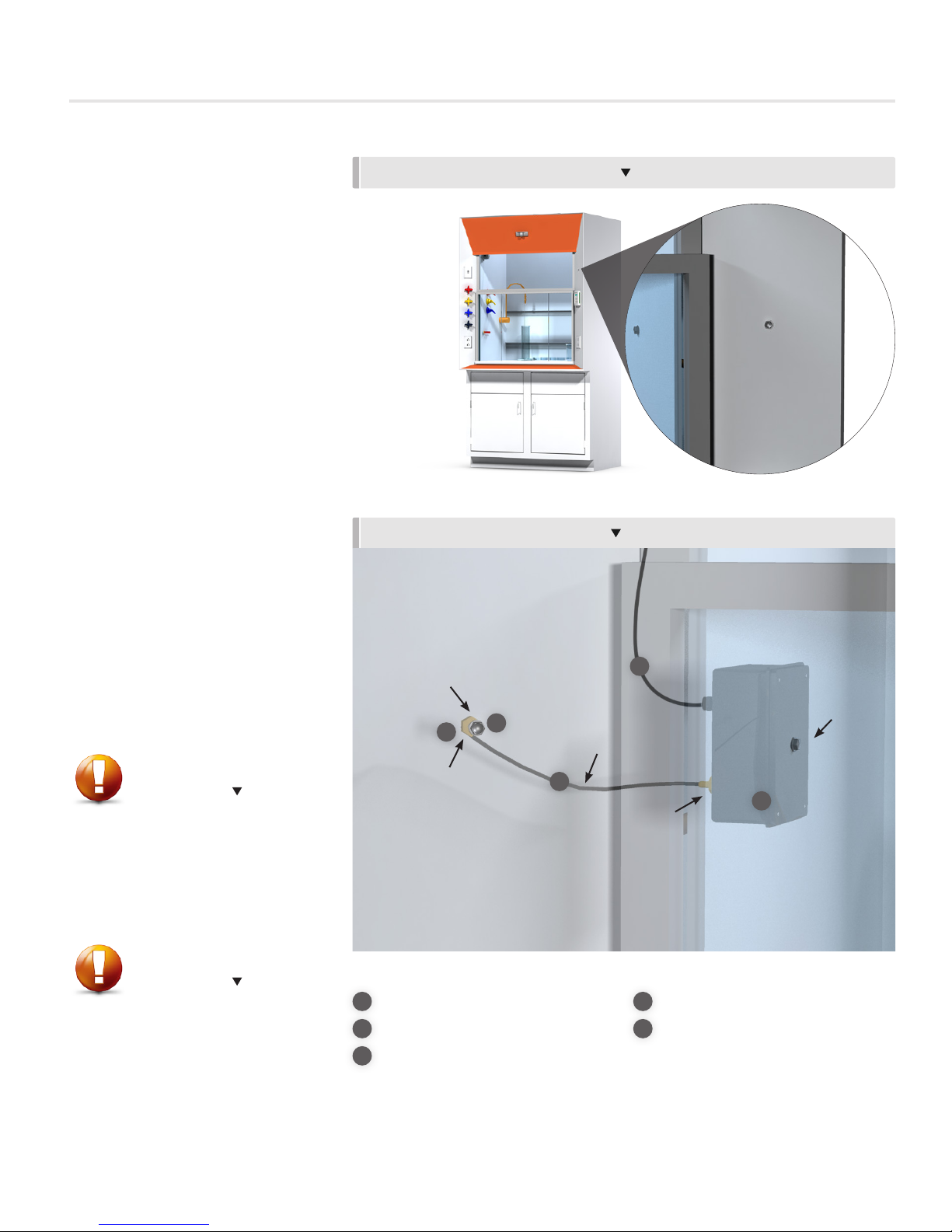
Sidewall Sensor (SWS) Installation
& Mounting
• The sidewall sensor consists of
multiple components: The Sidewall
Sensor, two hollowed bolts, a
male brass pressure port, and kink
resistant tubing.
• With the sash in the fully open
position, drill a 5/16” hole
5” above and 5” inward from
the base of the sash. Mount the
Sidewall Sensor behind the fume
hood wall, in the fume hood plenum
using one of the hollow bolts.
• To mount the exterior hollow bolt,
drill a 5/16” hole on the front of the
fume hood, no more than 12”
away from the Sidewall Sensor.
• Attach the provided male brass
pressure port to the exterior hollow
bolt.
• Use the kink-resistant tubing to
attach the brass pressure port from
the SWS to the brass pressure port
on the exterior hollow bolt.
• Attach the sensor cable to the SWS
and run the cable back to the FHC
mounted on the venturi valve or the
FHMX.
INSTALLATION & MOUNTING LOCATION
INSTALLATION & MOUNTING DETAILS
SENSOR
CABLE
HOLLOWED
BOLT #2
3
2
KINK
RESISTANT
TUBING
THE SIDEWALL SENSOR IS
MOUNTED BEHIND THE WALL, IN
THE FUME HOOD PLENUM, USING A
HOLLOWED BOLT PROVIDED.
4
HOLLOWED
BOLT #1
CAUTION
Mounting position is critical to ensure
the accuracy of the SWS. Ensure that
there are no sharp bends or kinks in the
tubing during the installation. Improper
installation will cause failure of the SWS.
CAUTION
If only one SWS is required, the SWS
must be wired into the SIDEWALL
SENSOR #1 port on the FHC/FHMX.
7
FUME HOOD CONTROLLER / MONITOR - Manual | pricecriticalcontrols.com
MALE BRASS
PRESSURE PORT
Required items:
1
Side Wall Sensor
2
Hollowed Bolt x2
3
Male Brass Pressure Port
5
1
BRASS
PRESSURE
PORT
4
Sensor Cable
5
Kink Resistant Tubing
SIDEWALL
SENSOR
FUME HOOD CONTROLLER / MONITOR
SECTION 2 - INSTALLATION & MOUNTING
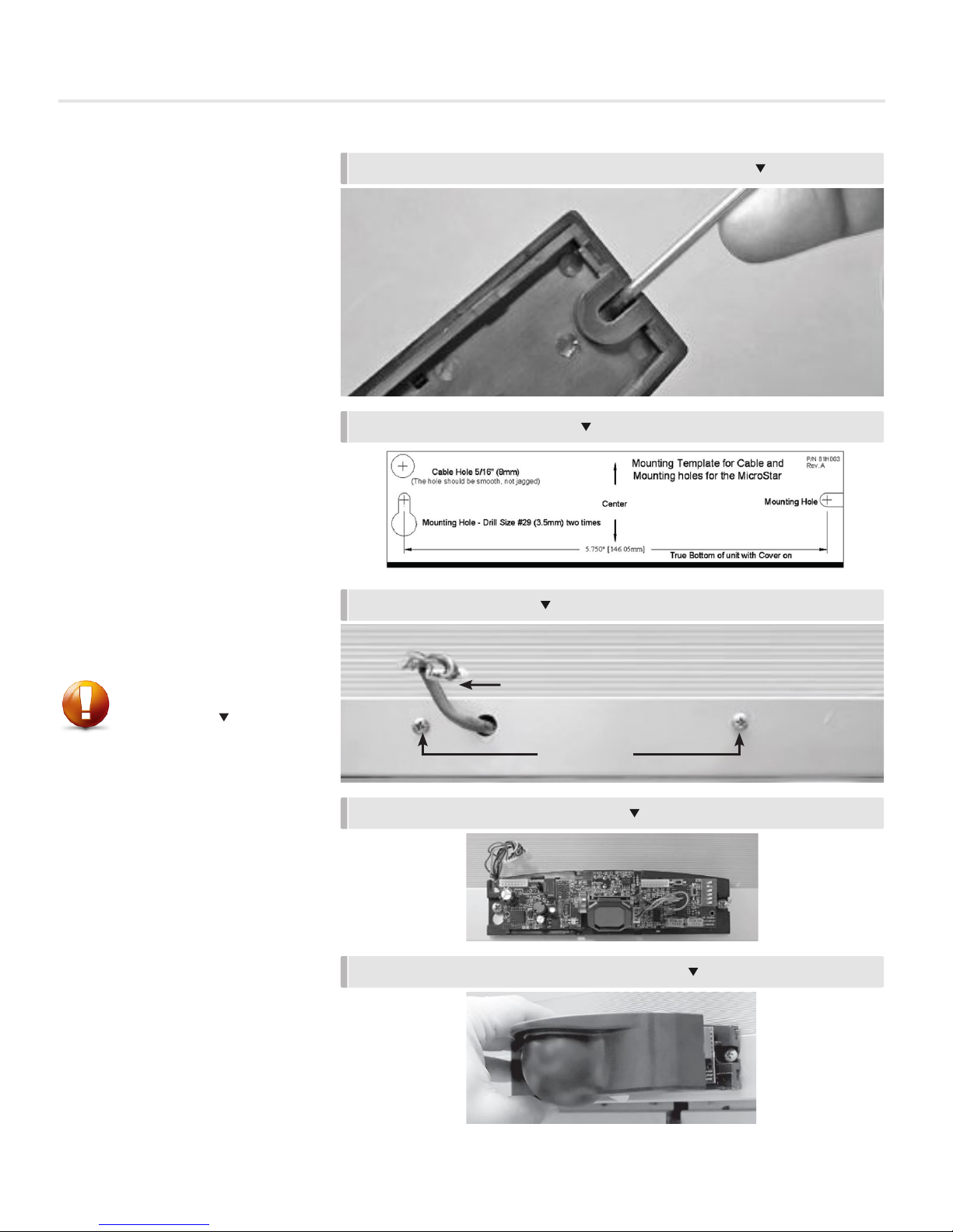
Presence Sensor (PS) Installation
and Mounting
1. Remove the cover of the presence
sensor by placing the blade of a
small screwdriver in the notch in
the right side of the cover as shown
(see Figure 1). Always remove the
cover in this manner.
2. Drill two screw pilot holes and one
wire passage according to the
template in Figure 2.
3. Insert mounting screws partially
into holes. Route the wire harness
through the wire passage hole as
shown in Figure 3.
4. Route the wire harness through
the hole in the presence sensor.
Install the presence sensor onto the
mounting screw and tighten.
5. Replace the cover by engaging
the left side first and then gently
snapping the cover into place
FIGURE 1 - INSERT SMALL SCREWDRIVER AND PRY UPWARDS
FIGURE 2 - MOUNTING TEMPLATE
FIGURE 3 - WIRE HARNESS
CAUTION
Remember to follow these safety
precautions:
• Shut off power to the FHC or
FHMX before wiring the sensor.
• Always ensure wiring is
located clear of any moving
parts to avoid damage.
POWER CABLE
MOUNTING SCREW
FIGURE 4 - MOUNTED PRESENCE SENSOR
FIGURE 5 - PRESENCE SENSOR FACTORY SETTINGS
pricecriticalcontrols.com | FUME HOOD CONTROLLER / MONITOR - Manual
8
 Loading...