

Price FFU series, FFU-HE-RSR-FC Installation And Service Manual
MANUAL – INSTALLATION + SERVICE
Fan Filter Unit
FFU Series
v100 – Issue Date: 04/03/18
© 2018 Price Industries Limited. All rights reserved.

FAN FILTER UNIT
TABLE OF CONTENTS
Product Overview
Read & save these instructions .................................... 1
Before you start ............................................................ 2
Introduction ..................................................................3
Installation & Service Instructions
Diffuser Module Installation ...........................................4
Speed Controllers ......................................................... 6
PSCSC/WK Speed Controller
Installation & Operation .............................................. 6
ECMSC/WK Speed Controller
Installation & Operation ............................................... 7
ECMDX/WK Speed Controller
Installation & Operation ............................................... 8
BACnet Flow Controller (BFC)
Installation & Operation .............................................. 10
Filter Installation .......................................................... 11
Room Side Replaceable Filter (RSR) ........................ 11
Bench Top Replaceable Filter (BTR)) ........................ 13
Optional Accessories .................................................. 15
Aerosol Sample Port, Static Port and
Aerosol Injection Port (INJ).......................................15
Filter/Motor Indicator LED (ML/FL) – RSR ................ 17
Filter/Motor Indicator LED (ML/FL) – BTR ............... 19
Motor/Filter Indicator BAS (MBAS/FBAS) ................ 22
Service Introductions ..................................................23
Motor Change ............................................................ 26
Top Access Motor/Blower Assembly ....................... 26
Room Side accessible Motor/Blower Assembly ....... 28
Technical Note: Aerosol Sample and Static Port..........32
Room Side Replaceable (RSR) ................................ 32
Bench Top Replaceable (BTR) ................................. 33
Controls ...................................................................... 34
ECMSC ................................................................... 34
ECMDX ................................................................... 37
BFC ........................................................................ 39
Technical Note: Design with VAV/Constant Flow Boxes
and Ducted Applications ............................................. 41
Balancing ................................................................... 42
Un-ducted Supply Units .......................................... 42
Ducted Supply – Pressure Independent and
Dependent Airflow Control .......................................43
Ducted Supply – Pressure Independent and
Dependent Airflow Control .......................................45
Troubleshooting .......................................................... 46
Changing Motor Programs ...................................... 46
Tips ......................................................................... 47
BTR Unit Replacement Parts ...................................... 48
RSR Unit Replacement Parts ...................................... 49
Wiring Diagrams ......................................................... 50
Warranty ..................................................................... 61
Pre-Filter Cleaning ................................................... 23
RSR Filter Removal and Replacement ..................... 24
BTR Filter Removal and Replacement ..................... 25
ii

FAN FILTER UNIT
PRODUCT OVERVIEW
Read and Save These Instructions
Warning! To reduce the risk of fire, electrical shock, or injury to persons, observe the following:
A. Installation work and electrical wiring must be done by qualified person(s) in accordance with all applicable codes and
standards, including fire-rated construction.
B. When cutting or drilling into wall or ceiling, do not damage electrical wiring and other hidden utilities.
C. Use this unit only in the manner intended by the manufacturer. If you have any questions, contact the manufacturer:
In the United States
2975 Shawnee Ridge Court
Suwanee, Georgia USA 30024
Ph: 770.623.8050
Fax: 770.623.6404
In Canada / International Export Sales Office
638 Raleigh Street
Winnipeg, Manitoba Canada R2K 3Z9
Ph: 204.669.4220
Fax: 204.663.2715
D. Before servicing or cleaning unit, switch power off at service panel and lock service panel to prevent power from being
switched on accidentally.
E. To reduce the risk of injury to persons, install the unit at least 7ft above grade or in ceiling.
priceindustries.com | FAN FILTER UNIT - Manual
priceindustries.com | FAN FILTER UNIT - Manual
1

FAN FILTER UNIT
PRODUCT OVERVIEW
Before You Start
Inspect all cartons and boxes for flaws and shipping damages.
If anything is discovered to be damaged, contact the shipping company and file a freight claim.
Ensure that all HEPA/ULPA filters are stored in a clean, dry location in a vertical position, as labeled on the carton.
Ensure ductwork is balanced to scheduled flow prior to proceeding.
NOTE: Extreme caution should be taken to avoid contact with filter media. Touching filter media may result in filter failure. Damage
to filters can occur during installation or during leak qualification testing. The filters supplied by Price have been 100% tested
and certified by the manufacturer to be free of defects and leaks. Price cannot accept responsibility for damage that occurs after
shipment, whether through transit, handling or installation, and will not replace filters under Price standard warranty.
To ensure fan filter units are properly balanced, read Technical Note: Design with VAV/Constant Flow Boxes and Ducted
Applications prior to starting installation.
A minimum of two (2) people will be required to install the filters.
2
FAN FILTER UNIT
PRODUCT OVERVIEW
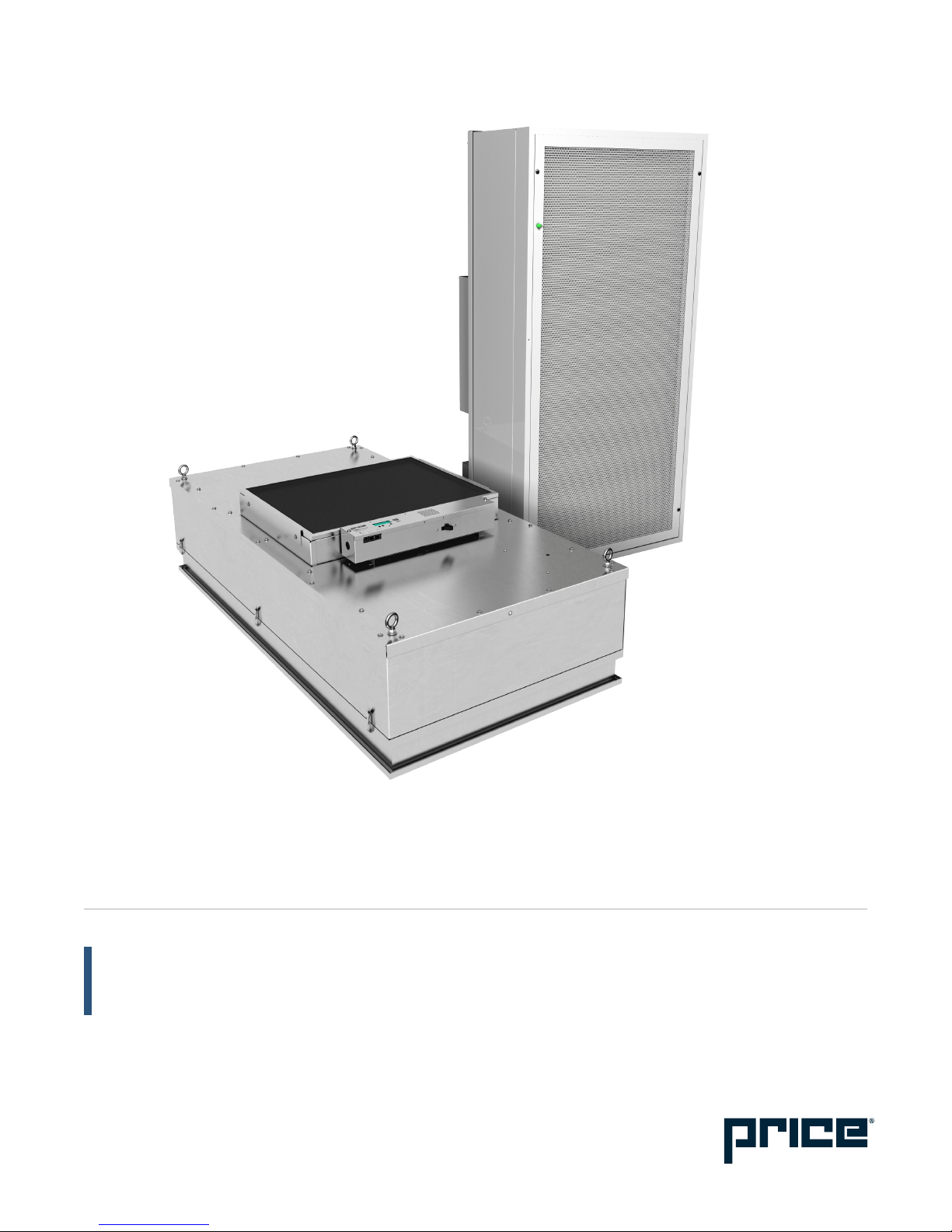
Introduction
Price Fan Filter Units (FFU) are ceiling module diffusers consisting of a fan/motor assembly and Roomside Removable (RSR), or
Bench Top Replaceable (BTR) filters. The module is designed to provide unidirectional vertical airflow of filtered, clean air over a
cleanroom space.
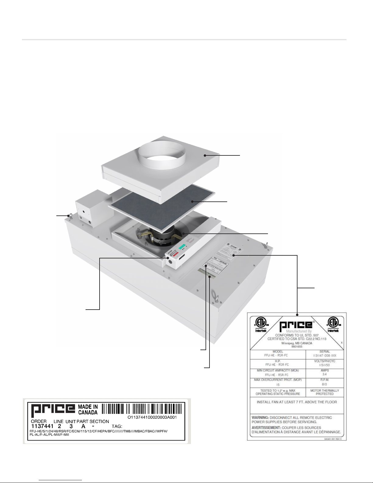
Fan Filter Units (FFU) models will have three (3) stickers located on the back of the plenum. For ease of troubleshooting assistance,
replacement parts, and general factory assistance, it is recommended that the order number, and model line string be used as
reference. This information can be found on the Factory Label.
OPTIONAL DUCT COLLAR
OPTIONAL PRE-FILTER
EYEBOLT
SPEED CONTROLLER
MOTOR/BLOWER ASSEMBLY
ETL LABEL
FACTORY PERFORMANCE LABEL
FACTORY LABEL
priceindustries.com | FAN FILTER UNIT - Manual
3
FAN FILTER UNIT
INSTALLATION & SERVICE INSTRUCTIONS
Diffuser Module Installation
The Price FFU will come completely assembled from the factory with the exception of the HEPA/ULPA filters, which will ship in its
own carton, and the speed controller wall kits (if selected).
NOTE: Do not open the HEPA/ULPA filters until they are ready to be installed in the FFU units. All construction in the space should
be complete, the site and upstream air should be clean so as not to unnecessarily load the filter.
Sample line string for Room Side Replaceable filter:
FFU-1-X//I/24/48/RSR/FC/ECM/115/10//CF//HEPA//BFC////DSW-115////RMB/ASSP/INJ//FL+ML+BACnet///WPFH/PL-AL/FAL//PL-B12/F-B12
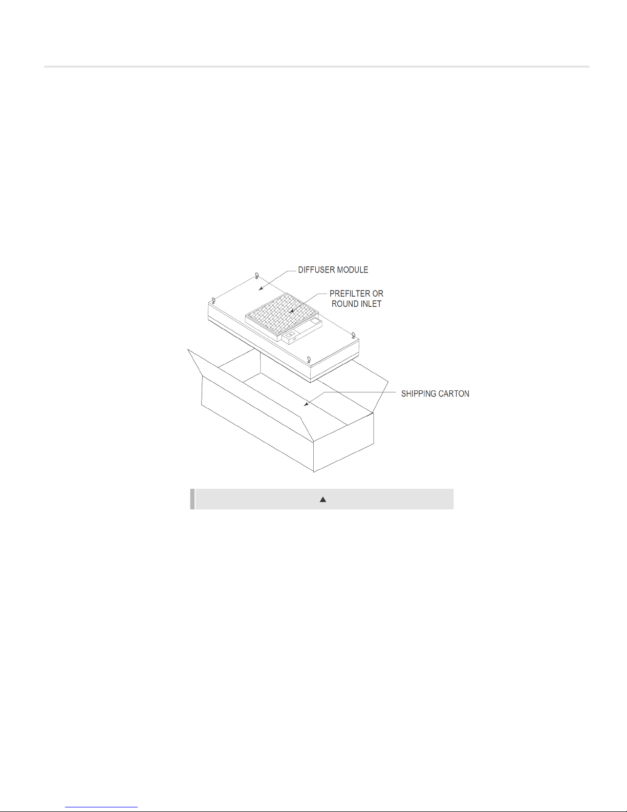
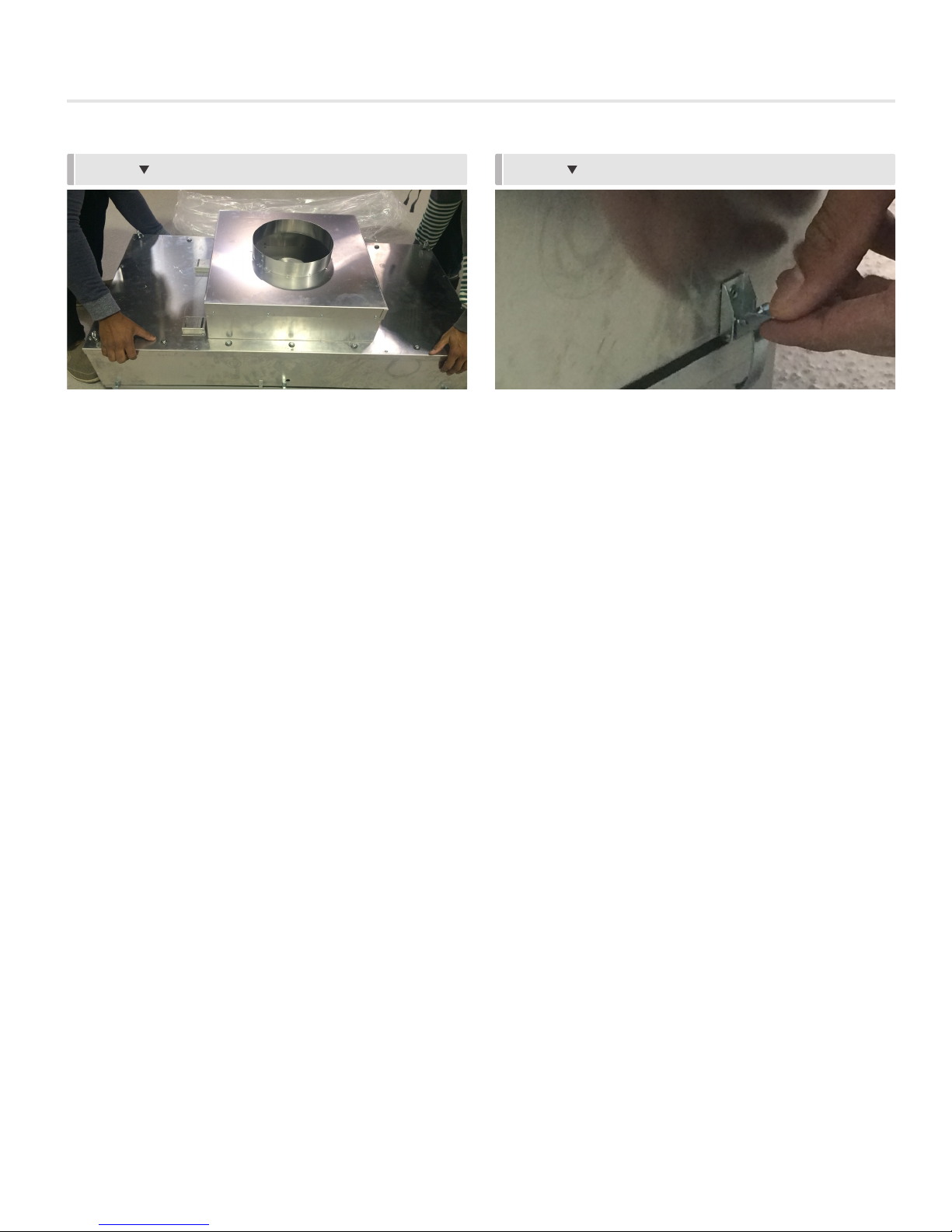
STEP 1: Remove FFU from shipping carton and inspect for any damage.
FIGURE 1: UNIT UNPACKING
NOTE: Ensure the HEPA/ULPA filter has been safely stored in a vertical position, per carton label, until ready for use.
STEP 2: If unit is Bench Top Replaceable (BTR) refer to page 13 for filter installation prior to proceeding. Once BTR filter is
installed, proceed to the next step. If unit is Room Side Replaceable (RSR), proceed directly to next step.
Sample line string for Bench Top Replaceable filter:
FFU-1-X//I/24/48/BTR/FC/ECM/115/10//CF//HEPA//BFC////DSW-115////TMB/ASSP///FL+ML+BACnet///WPFH/PL-AL///PLB12/
STEP 3: Raise the unit through the ceiling grid at an angle until entire unit is above the grid
STEP 4: Lower unit onto the backside of the tees.
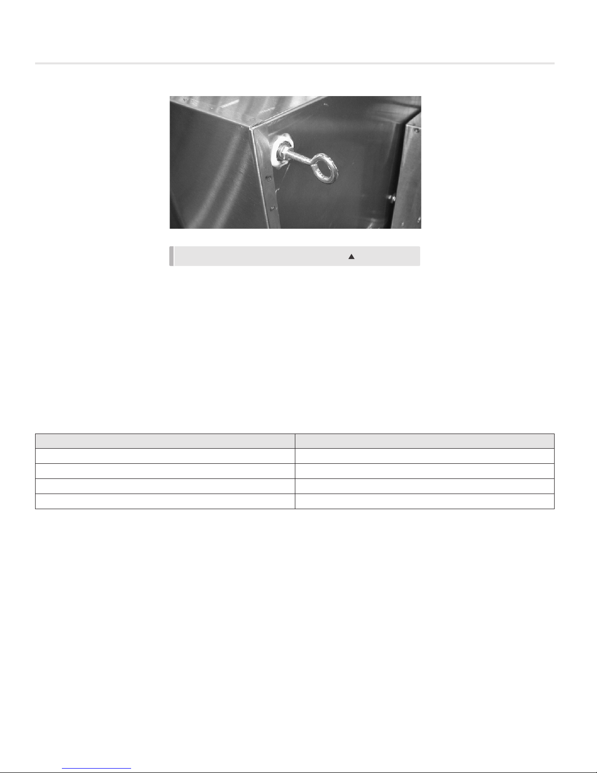
STEP 5: Secure the unit to the overhead structure using the eyebolts located on the back of the unit.
4
FAN FILTER UNIT
INSTALLATION & SERVICE INSTRUCTIONS
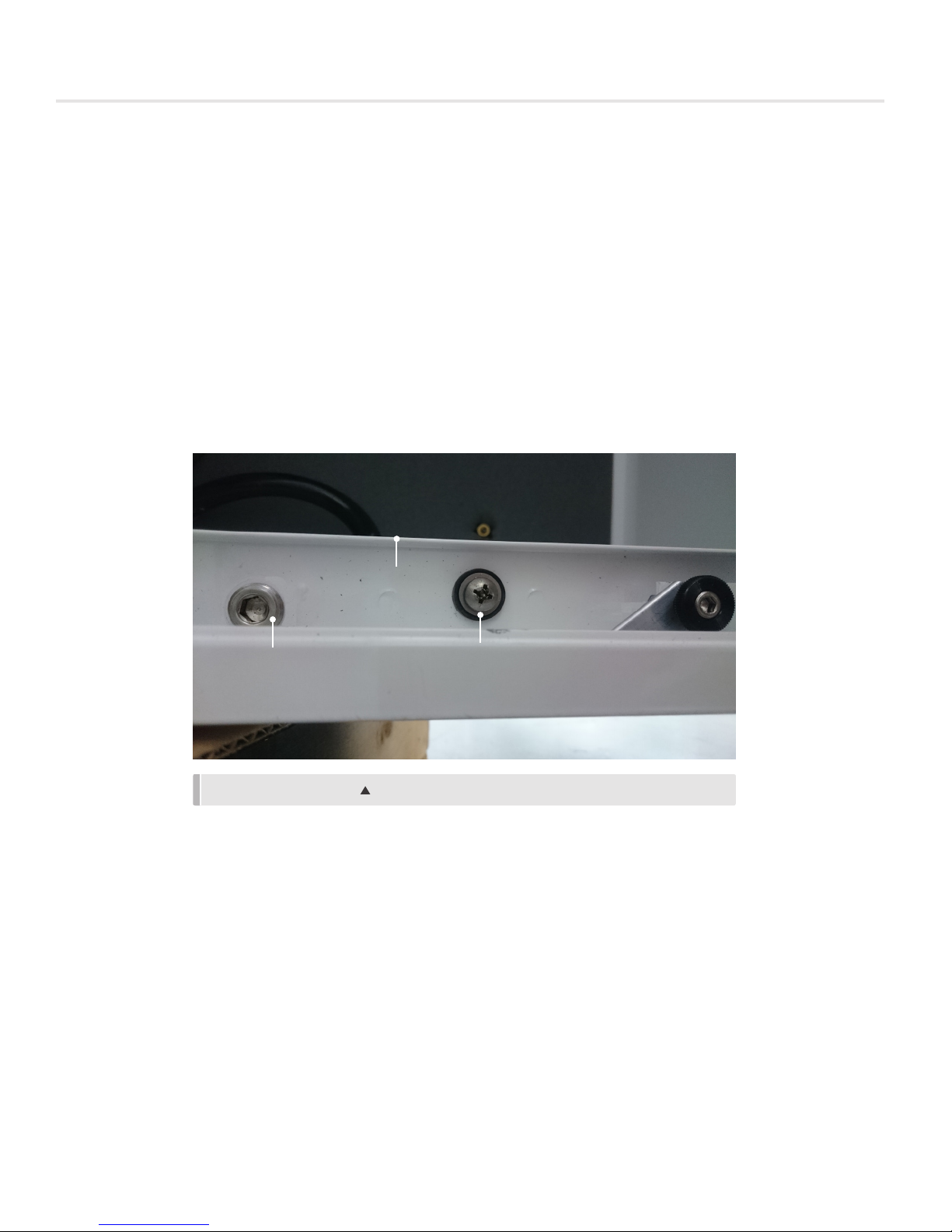
FIGURE 2: UNIT EYEBOLTS FOR MOUNTING
STEP 6: Adjust and level the unit so that it rests on the tees and there is adequate compression on the gasket to warrant a tight
seal.
Ensure that ceiling grid is properly gasket/sealed to prevent infiltration of unfiltered air from the ceiling plenum into the room side.
Above steps are manufacturer's suggested hanging techniques, always make sure to follow all local building codes, including
seismic, where applicable.
STEP 7: Refer to Factory Label to determine which speed controller is on the unit and use the following table for appropriate
reference page for the particular speed controller on your unit.
Sample line string:
FFU-1-X//I/24/48/RSR/FC/ECM/115/10//CF//HEPA//BFC////DSW-115////RMB/ASSP/INJ//FL+ML+BACnet///WPFH/PL-AL/FAL//PL-B12/F-B12
Speed Controller Page Reference
PSCSC/WK 6
ECMSC/WK 7
ECMDX/WK 8
BFC 10
NOTE: Depending on unit ordered, speed controller will be mounted on the unit itself, or, if a wall-kit option was selected, shipped
loose for field installation
priceindustries.com | FAN FILTER UNIT - Manual
5
FAN FILTER UNIT
INSTALLATION & SERVICE INSTRUCTIONS
Speed Controllers
PSCSC/WK Speed Controller Installation & Operation
Sample line string:
FFU-1-X//I/24/48/BTR/FC/PSC/115/10////HEPA//PSCSC//WK-PSC//DSW-115////TMB/ASSP//////WPFH/PL-AL///PL-B12/
FIGURE 3: PSC SPEED CONTROLLER WITH WALL KIT OPTION
If unit does not have the wall kit (WK) option, proceed to step 11A.
Sample line string:
FFU-1-X//I/24/48/BTR/FC/PSC/115/10////HEPA//PSCSC/////DSW-115////TMB/ASSP//////WPFH/PL-AL///PL-B12/
STEP 8A: Locate pre-installed electric box for wall-mounted speed controller.
STEP 9A: Wire speed controller according to wiring diagram found on page 57. Wall-mounted speed controller will be wired in
series with the motor.
NOTE: Wiring should be carried out by a certified electrician and meet national and local electrical codes.
STEP 10A: Attach the wall-mounted controls faceplate to the electrical box using the screws provided.
STEP 11A: Wire the unit according to appropriate wiring diagram. If Power Cord (PC) option is selected, simply insert plug end
into electrical socket.
Sample line string:
FFU-1-X//I/24/48/BTR/FC/PSC/115/10////HEPA//PSCSC/////DSW-115/PC-115///TMB/ASSP//////WPFH/PL-AL///PL-B12/
NOTE: Wiring should be carried out by a certified electrician and meet national and local electrical codes.
STEP 12A: If using RSR filter, refer to page 11 for filter installation instructions.
NOTE: Ensure that the space is clean, free of debris, and ducts are cleaned and ready for operation prior to installation of filter.
STEP 13A: Ensure proper voltage is hooked up to the unit.
STEP 14A: Proceed to controls and balancing section on page 42.
NOTE: Clockwise rotation will increase airflow, counter-clockwise rotation will decrease airflow.
NOTE: If unit is ducted, refer to Technical Note: Balancing Ducted Units on page 44 of this manual.
6
FAN FILTER UNIT
INSTALLATION & SERVICE INSTRUCTIONS
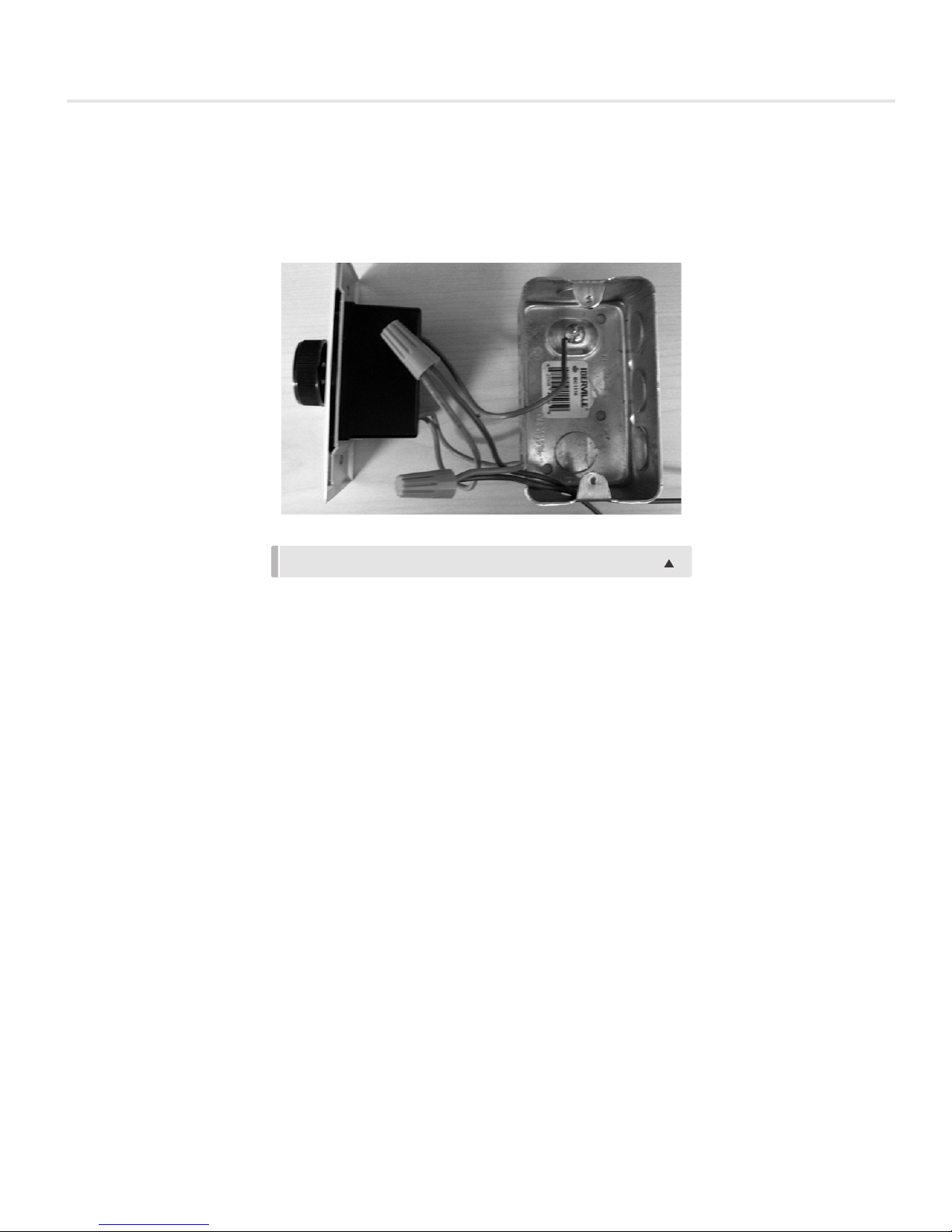
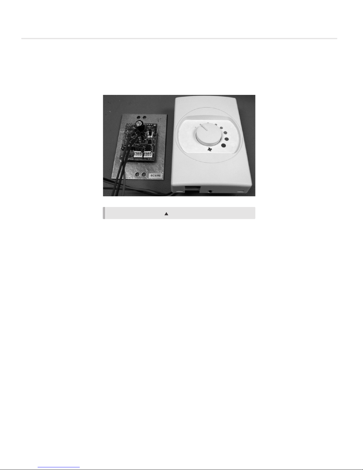
ECMSC/WK Speed Controller Installation and Operation
Sample line string below:
FFU-HE/24/48/RSR/BC/ECM/115/10//CT//HEPA//ECMSC// WK /DSW/PC/TMB/ATS/ML/FL/WPF/PL-AL/F-AL/PL-B12/F-B12
FIGURE 4: ECMSC/WK
If unit does not have the wall kit (WK) option, proceed to STEP 11B.
Sample line string:
FFU-1-X//I/24/48/RSR/FC/ECM/115/10//CF//HEPA//ECMSC/////DSW-115////RMB/ASSP//////WPFH/PL-AL/F-AL//PL-B12/F-B12
STEP 8B: Locate pre-installed electrical box for wall-mounted speed controller.
STEP 9B: Wire speed controller according to wiring diagram found on page 58 - 60. Motor speed controller will have color coded
wires and must be wired to the matching colors on the wall-mounted portion.
NOTE: Wiring should be carried out by a certified electrician and meet national and local electrical codes.
STEP 10B: Attach the wall-mounted controls faceplate to the electrical box using the screws provided.
STEP 11B: Wire the unit according to appropriate wiring diagram. If Power Cord (PC) option is selected, simply insert plug end
into electrical socket.
Sample line string:
FFU-1-X//I/24/48/RSR/FC/ECM/115/10//CF//HEPA//ECMSC//WK-ECMSC//DSW-115//PC-115/RMB/ASSP//////WPFH/PL-AL/FAL//PL-B12/F-B12
NOTE: Wiring should be carried out by a certified electrician and meet national and local electrical codes.
STEP 12B: If using RSR filter, refer to page 11 for filter installation instructions.
NOTE: Ensure that the space is clean, free of debris, and that ducts are cleaned and ready for operation prior to installation of filter
STEP 13B: Ensure proper Voltage is hooked up to the unit.
STEP 14B: Proceed to controls and balancing section on pages 42.
priceindustries.com | FAN FILTER UNIT - Manual
7
FAN FILTER UNIT
INSTALLATION & SERVICE INSTRUCTIONS
Speed Controllers
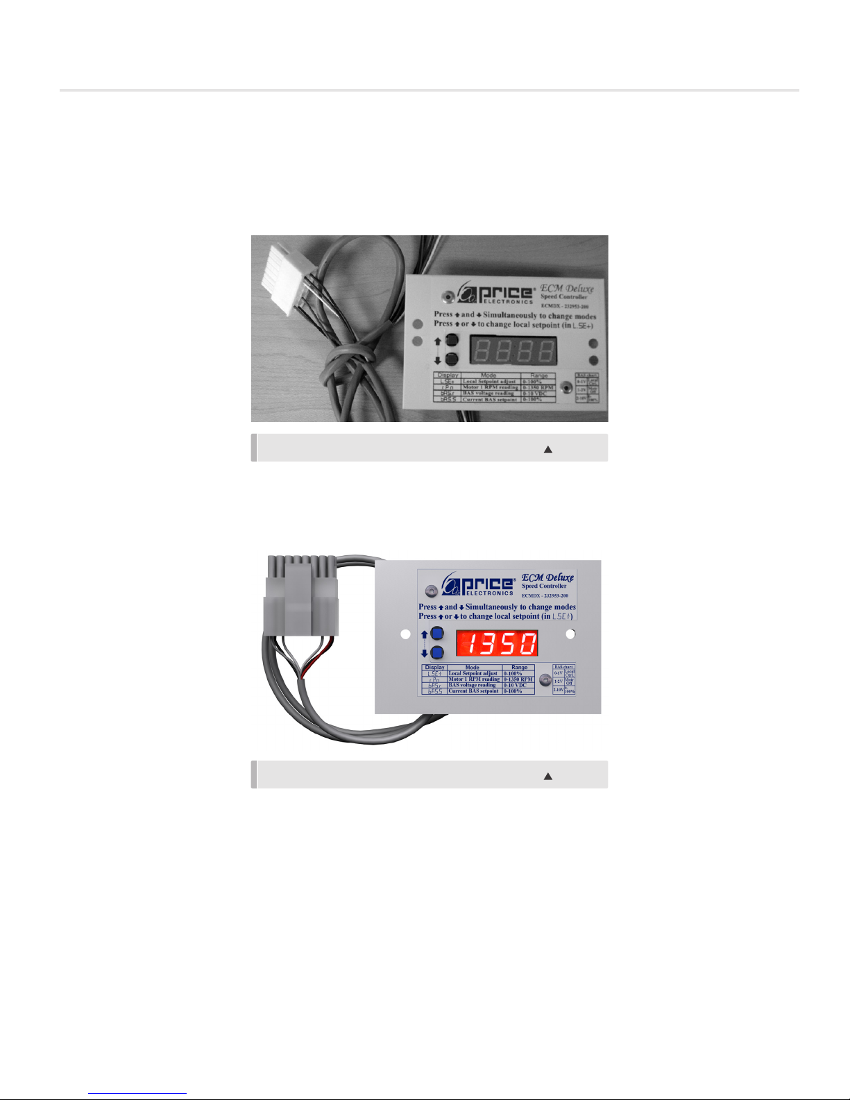
ECMDX/WK Speed Controller Installation and Operation
Sample line string:
FFU-HE/24/48/RSR/BC/ECM/115/10//CT//HEPA//ECMDX// /DSW/PC/TMB/ATS/ML/FL/WPF/PL-AL/F-AL/PL-B12/F-B12
If unit does not have the wall kit (WK) option, proceed to STEP 11C.
Sample line string:
FFU-HE/24/48/RSR/BC/ECM/115/10//CT//HEPA//ECMDX//WK/DSW/PC/TMB/ATS/ML/FL/WPF/PL-AL/F-AL/PL-B12/F-B12
STEP 8C: Locate pre-installed electrical box for wall-mounted speed controller.
NOTE: Wall kit must be mounted horizontally, as shown above.
FIGURE 5: ECMDX WALL KIT SPEED CONTROLLER
FIGURE 6: ECMDX WALL KIT SPEED CONTROLLER
STEP 9C: Wire unit according to wiring diagram found on page 58 - 60. Motor speed controller will have color coded wires and
must be wired to the matching colors on the wall-mounted portion.
NOTE: 24VAC and COMMON will need to be run from the terminal block in the control box to the terminals listed 24VAC HOT, and
COMMON on the wall-mounted portion.
NOTE: Wiring should be carried out by a certified electrician and meet national and local electrical codes.
STEP 10C: Attach the wall-mounted controls faceplate to the electrical box using the screws provided.
STEP 11C: Wire the unit according to appropriate wiring diagram. If Power Cord (PC) option is selected, simply insert plug end
into electrical socket
8
FAN FILTER UNIT
INSTALLATION & SERVICE INSTRUCTIONS
Sample line string:
FFU-HE/24/48/RSR/BC/ECM/115/10//CT//HEPA//ECMSC///DSW/PC/TMB/ATS/ML/FL/WPF/PL-AL/F-AL/PL-B12/F-B12
NOTE: Wiring should be carried out by a certified electrician and meet national and local electrical codes.
STEP 12C: If using RSR filter, refer to page 11 for filter installation instructions.
NOTE: Ensure that the space is clean, free of debris, and that ducts are cleaned and ready for operation prior to installation of filter
STEP 13C: Ensure proper Voltage is hooked up.
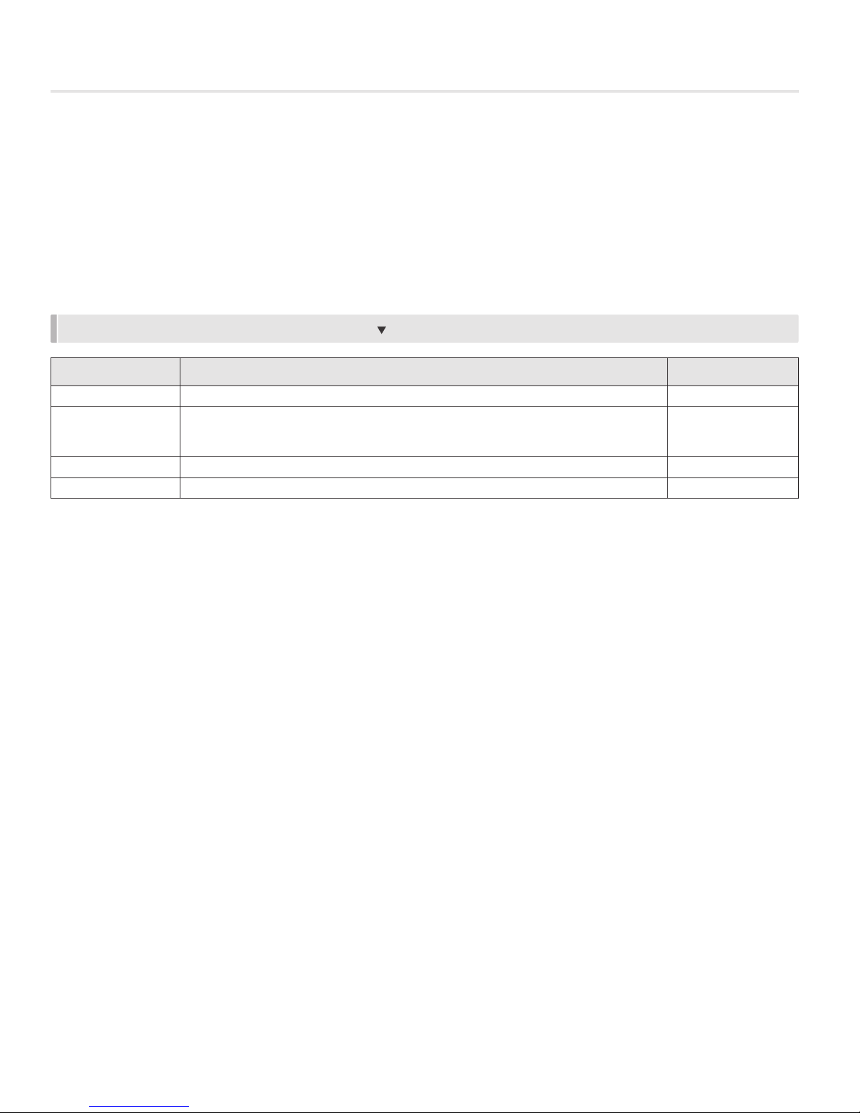
NOTE: ECMDX Speed Controllers have multiple modes, which are listed below:
TABLE I: ECMDX SPEED CONTROLLER DISPLAY CODES
Display Mode Range
L.SEt Local Set point – Manual speed adjust mode (use UP / DOWN to adjust) 0 - 100%
RPM – Shows current RPM of motor 1
rPn
bAS.r BAS Remote – BAS Mode – Voltage signal (Max reading is 9.99 VDC) 0 - 9.99 VDC
bAS.S BAS Set point – Current BAS set point 0 - 100%
If E001 – no RPM pulses are being read, check 6 position cable
If E002 – RPM reading is above 2000 RPM, check primary air
0 - 2500 RPM
STEP 14C: Proceed to controls and balancing section on page 42.
priceindustries.com | FAN FILTER UNIT - Manual
9
FAN FILTER UNIT
INSTALLATION & SERVICE INSTRUCTIONS
Speed Controllers
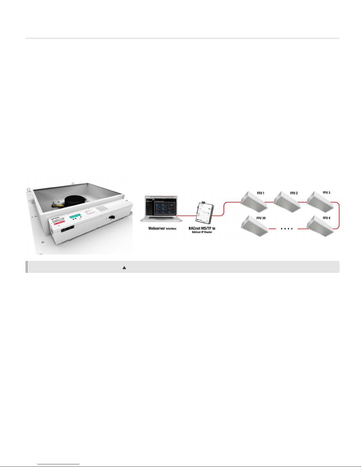
BACnet Flow Controller (BFC) Installation and Operation
Sample line string:
FFU-1-1//I/24/48/RSR/FC/ECM/115/10//CF//HEPA//BFC////DSW-115////RMB/ASSP/INJ//FL+ML+BACnet///WPFH/PL-AL/FAL//PL-B12/F-B12
STEP 8D: Wire unit according to appropriate wiring diagram. If Power Cord (PC) option is selected, simply insert plug end into
electrical socket.
NOTE: Polarity is important and must be observed. It is also vital that the 24 VAC common side of the transformer be Earth
grounded.
STEP 9D: Hook up applicable BACnet, and/or local Building Automation System (BAS) according to wiring diagram found on
page 58 - 60. For multiple units, use provided cable to daisy chain units together. If using BAS or Local Set point, reference the
BFC controls section on page 39 for applicable instructions.
FIGURE 7: DAISY CHAINED FFU UNITS
NOTE: For additional information on BACnet, and the BFC controller, refer to the BACnet Wiring Guidelines, and BFC Manual which
are available on the Price Industries website @ priceindustries.com
STEP 10D: Wire the unit according to the appropriate wiring diagram found on page 58 – 60. If power cord option is selected,
simply insert the plug end into the electric socket.
Sample line string:
FFU-1-1//I/24/48/RSR/FC/ECM/115/10//CF//HEPA//BFC////DSW-115//PC-115//RMB/ASSP/INJ//FL+ML+BACnet///WPFH/PLAL/F-AL//PL-B12/F-B12
NOTE: Wiring should be carried out by a certified electrician and meet national and local electrical codes.
STEP 11D: If using RSR filter, refer to page 11 for installation instructions.
NOTE: Ensure that the space is clean, free of debris, and that ducts are cleaned and ready for operation prior to installation of filter.
STEP 12D: Ensure proper Voltage is hooked up to the unit.
STEP 13D: Proceed to controls and balancing section on page 42.
10
FAN FILTER UNIT
INSTALLATION & SERVICE INSTRUCTIONS
Filter Installation
Room Side Replaceable Filter (RSR)
Sample line string:
FFU-1-1//I/24/48/RSR/FC/ECM/115/10//CF//HEPA//BFC////DSW-115//PC-115//RMB/ASSP/INJ//FL+ML+BACnet/// WPFH/PLAL/F-AL//PL-B12/F-B12
NOTE: Extreme caution should be taken to avoid contact with filter media. Touching filter media may result in filter failure. Damage
to filters can occur during installation or during leak qualification testing. The filters supplied by Price have been 100% tested
and certified by the manufacturer to be free of defects and leaks. Price cannot accept responsibility for damage that occurs after
shipment, whether through transit, handling or installation, and will not replace filters under our standard warranty. shipment,
whether through transit, handling or installation, and will not replace filters under our standard warranty.
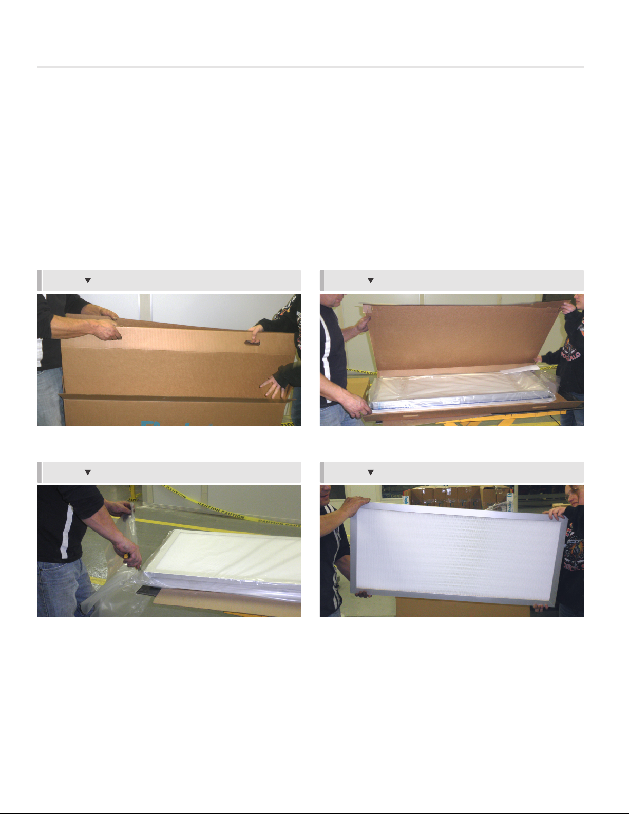
STEP 1
Remove filter from box using handles Place filter on flat surface or table.
STEP 3
STEP 2
STEP 4
Cut plastic bag and remove filter with care. To handle the filter, grasp by the frame only.
priceindustries.com | FAN FILTER UNIT - Manual
11
FAN FILTER UNIT
INSTALLATION & SERVICE INSTRUCTIONS
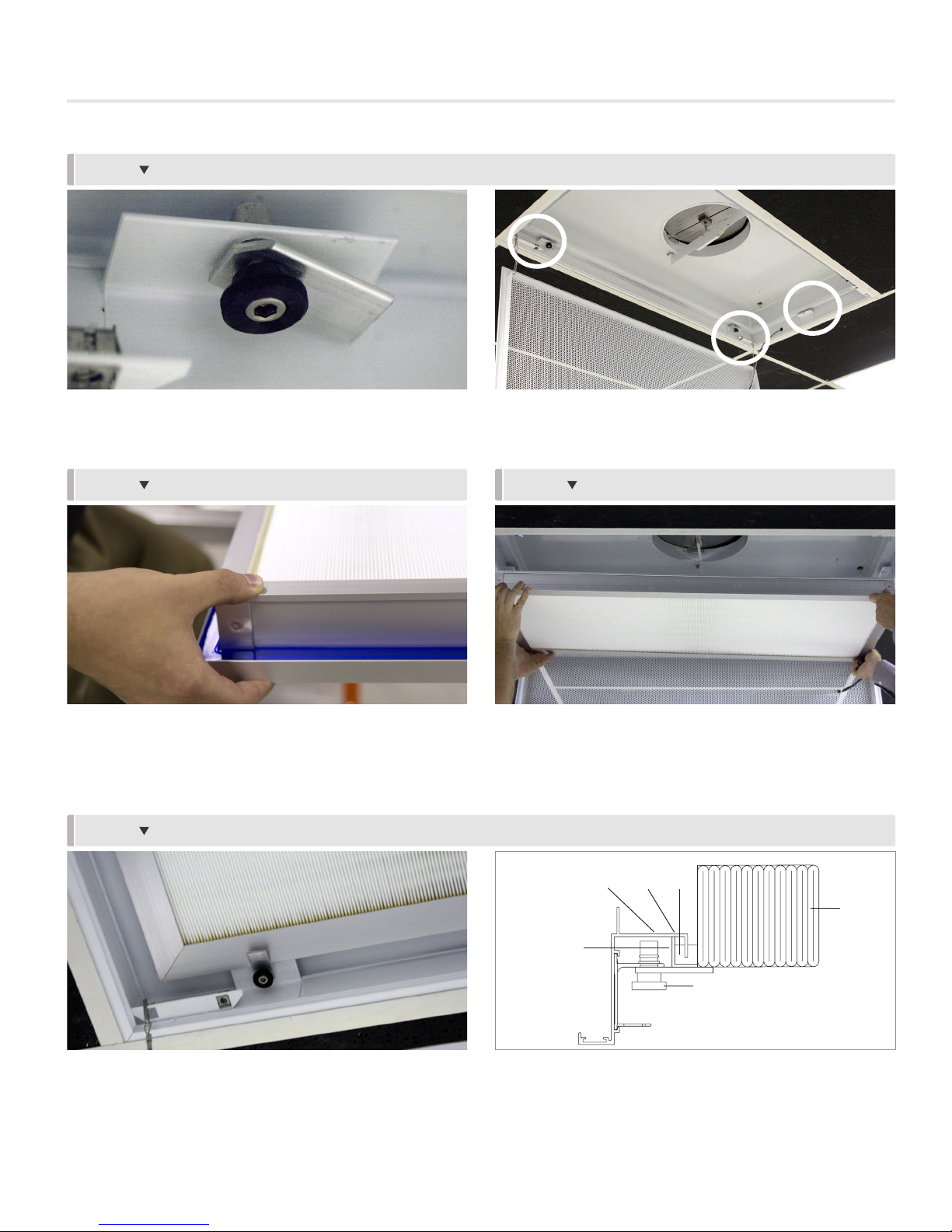
STEP 5
Loosen cam locks on diffuser to prepare filter for installation. Be sure latches are turned inwards so as not to interfere with filter frame.
NOTE: Note location of filter alignment guides (minimum one per side, dependent on size).
STEP 6
Raise the filter in place using two people and being careful not
to contact the filter media.
STEP 8
STEP 7
Using the alignment guides, raise the filter into place, ensuring
filter gel seal channel seat into knife edge of plenum.
NOTE: Do not bottom out gel seal in plenum knife edge. The gel
seal needs to ‘float’ in gel seal to ensure proper seal.
POINT
GEL
SEAL
FILTER
MEDIA
KNIFE
EDGE
CONTACT
Secure filter in place using the cam locks. Tighten until no
further rotations can be made. No tools are required to tighten,
and using one may cause damage to filter gel seal.
12
HEPA FILTER
OUTER FRAME
CAM
LOCK
Ensure HEPA filter outer frame is in contact with horizontal
knife edge of frame. Note that diffuser knife edge cannot
bottom out in HEPA filter gel seal.
FAN FILTER UNIT
INSTALLATION & SERVICE INSTRUCTIONS
Filter Installation
Bench Top Replaceable Filter (BTR)
Sample line string:
FFU-1-1//I/24/48/BTR/FC/ECM/115/10//CF//HEPA//BFC////DSW-115//PC-115//TMB/ASSP///FL+ML+BACnet/// WPFH/PLAL///PL-B12/
NOTE: Extreme caution should be taken to avoid contact with filter media. Touching filter media may result in filter failure.
Damage to filters can occur during installation or during leak qualification testing. The filters supplied by Price have been 100%
tested and certified by the manufacturer to be free of defects and leaks. Price cannot accept responsibility for damage that occurs
after shipment, whether through transit, handling or installation, and will not replace filters under our standard warranty.
NOTE: If ordered with Filter or Motor LED Indicator (ML/FL), refer to LED installation instructions which must be done at same time
as filter installation.
FFU-HE/24/48/BTR/BC/ECM/115/10//CT//HEPA//ECMDX//WK/DSW/PC/TMB///ML/FL/WPF/PL-AL///PL-MILL//
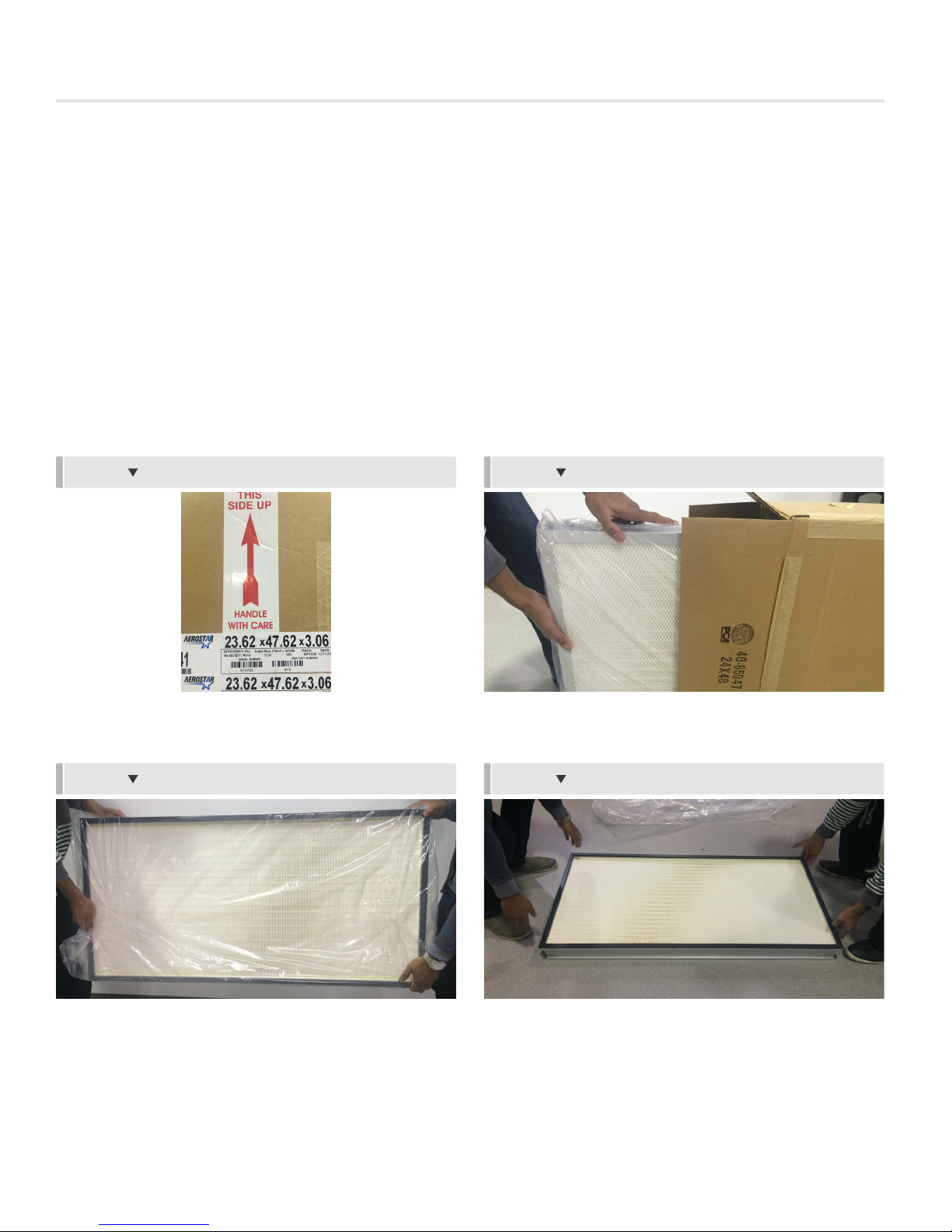
STEP 2 STEP 1
Place filter box on floor, careful to set box in correct orientation,
as per the arrow.
Place the filter gently on the floor, remove the tape, and take
the filter out of the bag.
Remove filter from box being careful not to touch filter media.
STEP 4 STEP 3
Place filter on a flat, clean, protecting surface with the
expanded face screen on the bottom. Make sure to protect
face LED if this has been selected as an option.
priceindustries.com | FAN FILTER UNIT - Manual
13
FAN FILTER UNIT
INSTALLATION & SERVICE INSTRUCTIONS
STEP 6 STEP 5
Place FFU top cap assembly onto filter’s gasket flange/ frame,
being careful to not damage the filter media.
Attach filter to top cap assembly by hooking and securing
latches. Gasket may need to be compressed to grab channel
with latch.
14
FAN FILTER UNIT
INSTALLATION & SERVICE INSTRUCTIONS
Optional Accessories
Aerosol Sample Port, Static Port and Aerosol Injection Port (INJ)
Sample line string below:
FFU-HE/24/48/RSR/BC/ECM/115/10//CT//HEPA//ECMDX//WK/DSW/PC/TMB/AT S/ML/FL/WPF/PL-AL/F-AL/PL-B12/F-B12
STEP 1: If unit has room side removable filter (RSR), remove diffusers perforated face by turning quarter turn fasteners holding
face in place.
FFU-HE/24/48/RSR/BC/ECM/115/10//CT//HEPA//ECMDX//WK/DSW/PC/TMB/ATS/ML/FL/WPF/PL-AL/F-AL/PL-B12/F-B12
NOTE: Safety cables will be attached to the diffuser face, but care should be taken to ensure that diffuser face does not swing and
injure anyone.
If unit is bench top removable (BTR), proceed to next step.
STEP 2: Remove threaded plug covering ATS port using a 5/16” hex screw driver.
KNIFE EDGE
ATS PORT
STATIC PRESSURE
PORT
DIFFUSER FACE
FRAME
UNIT PORT LOCATIONS
STEP 3: Insert aerosol test fitting or adaptor (the aerosol injection port has a 3/8” NPT internal thread) into Aerosol Injection port.
NOTE: An adaptor/test fitting that is longer than 1.5” and/or wider than 1” will not fit.
STEP 4: Inject aerosol test agent and measure particulate counts according to local codes.
NOTE: Aerosol Sample port can be used to measure upstream particle counts. Refer to page 15 for static pressure port details.
STEP 5: Disconnect test equipment, and reinstall plugs in the static pressure (if applicable) and aerosol injection ports. Reinstall
diffuser face (if applicable).
If the safety cables were also disconnected when removing the face, they must be reattached. When reinstalling the face, care
should be taken to tuck safety cables in place without damaging the filter.
NOTE: Airflow and aerosol challenge concentration should be kept uniform during the test. Static pressure and concentration may
be sampled through the static pressure port during the test, if required, to verify flow and concentration.
priceindustries.com | FAN FILTER UNIT - Manual
15
FAN FILTER UNIT
INSTALLATION & SERVICE INSTRUCTIONS
TABLE II outlines a few possible problems that may be encountered during leakage testing. This chart is intended as a quick
troubleshooting guide, and is not exhaustive. All local and applicable codes should be followed.
TABLE II: LEAKAGE TEST OUTCOMES & POSSIBLE SOLUTIONS
Display Mode Range
Leakage at the perimeter of the
filter
Pinhole leaks detected in filter
Leakage at the perimeter of the fan
filter unit
Particle Counter is beeping at
multiple locations, even away from
filter face
Improper filter installation
Improper handling of
filter/damage during installation
Improper seal between unit and
ceiling plenum
Possible leakage through
adjacent lights, diffusers, and/or
ceiling panels
Gently remove the filter, verify that the gel seal is intact and
undam- aged, and carefully reseat the filter in the knife edge
frame and latch in place.
Filter may be repaired by a trained technician.
Check seal between unit and ceiling plenum and seal as
required.
Isolate unit by placing cardboard or sheet metal to create
vertical 'walls' extending 2ft below the ceiling plane. If filter
passes, sealing of adjacent lights, diffusers, and/or ceiling
panels may be required.
16
FAN FILTER UNIT
INSTALLATION & SERVICE INSTRUCTIONS
Filter/Motor Indicator LED (ML/FL) – RSR
Sample line string:
FFU-1-1//I/24/48/RSR/FC/ECM/115/10//CF//HEPA//BFC////DSW-115//PC-115//RMB/ASSP/INJ//FL+ML+BACnet/// WPFH/PLAL/F-AL//PL-B12/F-B12
LED Operation
Option Code
Filter LED FL
Motor
LED
ML
LED
Color
Green None
Yellow Change Filter
Green None
Red Troubleshoot Motor
Action Notes
Indicates normal operation until filter pressure drop exceeds
calibrated pressure drop (factory set at 1.5x clean filter pressure).
Indicates filter pressure drop has exceeded calbirated setting (factory
set at 1.5x clean filter pressure.
Indicates normal motor operation when the static pressure is above
0.2" w.g.
Indicates motor is not in operation, and that unit static pressure is
below 0.2" w.g.
Calibration
Filter LED will come factory set to activate at the pressure drops listed in the Table below.
Filter Pressure @ 90fpm [in w.g.] 1.5x Clean Filter [in w.g.]
HEPA 0.4 0.6
Filter Indicator Set Points
ULPA 0.6 0.9
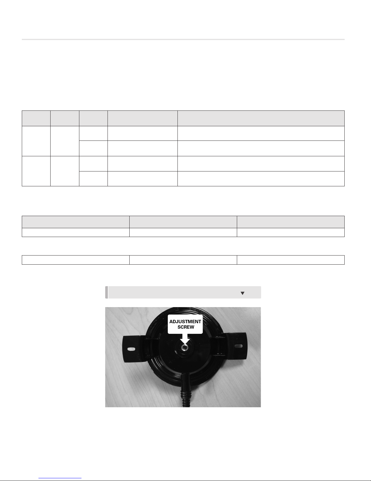
If different set points are desired, they can be adjusted as follows:
FIGURE 9: PRESSURE SWITCH ADJUSTMENT SCREW.
STEP 1: Remove Loctite from adjustment screw hole.
priceindustries.com | FAN FILTER UNIT - Manual
17

FAN FILTER UNIT
INSTALLATION & SERVICE INSTRUCTIONS
STEP 2: Calculate number of turns required based on difference between factory set point and desired set point using the
following chart.
FIGURE 10: RSR FILTER LED SET POINT ADJUSTMENT.
1.00
0.90
0.80
0.70
0.60
0.50
0.40
0.30
0.20
Set Point in Inches w.g.
0.10
0.00
0 1 2 3 4 5
Turns of Set Point Adjustment Screw
(from starting point at 0.25” w.g.)
Example:
HEPA filter with desired set point of 0.9 in w.g.
Number of turns at 0.9 in w.g. = 4
Number of turns at factory set point of 0.6 in w.g. = 2.2
Number of turns to field set = 4 – 2.2 = 1.8 (approximately)
NOTE: Maximum available pressure setting is 1.0” w.g. Do not exceed 4 ½ turns (total).
STEP 3: Turn screw clockwise the number of turns calculated above. You will need a 1.5mm hex Allen wrench
STEP 4: To check filter pressure set point and/or to fine tune, insert Magnehelic gauge into the static pressure port (located along
knife edge of diffuser – diffuser face must be removed to access).
STEP 5: Using an obstruction (piece of cardboard or equivalent), slowly increasing pressure on the unit by blocking off more and
more of the diffuser face until the LED turns from green to yellow.
STEP 6: Take pressure measurement at point the LED changed color and rotate the adjustment screw until desired pressure set
point is reached.
18
 Loading...